Self-regulating Batting Insulation
MASON; Vanessa ; et al.
U.S. patent application number 16/342628 was filed with the patent office on 2019-09-05 for self-regulating batting insulation. This patent application is currently assigned to PRIMALOFT, INC.. The applicant listed for this patent is PRIMALOFT, INC.. Invention is credited to Robert DEMPSEY, Vanessa MASON.
| Application Number | 20190271104 16/342628 |
| Document ID | / |
| Family ID | 62241942 |
| Filed Date | 2019-09-05 |


| United States Patent Application | 20190271104 |
| Kind Code | A1 |
| MASON; Vanessa ; et al. | September 5, 2019 |
SELF-REGULATING BATTING INSULATION
Abstract
Self-regulating insulative batting is provided. The batting includes a blend of a plurality of fibers including functional fibers and non-functional fibers. The plurality of fibers are non-woven and oriented substantially vertically along a thickness direction of the batting. The functional fibers are configured to self-regulate at least one insulative quality of the batting based on changes in at least one environmental condition interacting with the batting. At least one of the length and thickness of the functional fibers changes based on changes in at least one environmental condition interacting with the batting. Articles comprising the self-regulating batting and methods of making the self-regulating batting are also provided.
| Inventors: | MASON; Vanessa; (Rexford, NY) ; DEMPSEY; Robert; (Mechanicville, NY) | ||||||||||
| Applicant: |
|
||||||||||
|---|---|---|---|---|---|---|---|---|---|---|---|
| Assignee: | PRIMALOFT, INC. Latham NY |
||||||||||
| Family ID: | 62241942 | ||||||||||
| Appl. No.: | 16/342628 | ||||||||||
| Filed: | November 28, 2017 | ||||||||||
| PCT Filed: | November 28, 2017 | ||||||||||
| PCT NO: | PCT/US2017/063377 | ||||||||||
| 371 Date: | April 17, 2019 |
Related U.S. Patent Documents
| Application Number | Filing Date | Patent Number | ||
|---|---|---|---|---|
| 62427152 | Nov 29, 2016 | |||
| Current U.S. Class: | 1/1 |
| Current CPC Class: | D10B 2501/04 20130101; D10B 2401/04 20130101; D04H 1/02 20130101; D04H 1/4382 20130101; D10B 2503/06 20130101 |
| International Class: | D04H 1/02 20060101 D04H001/02; D04H 1/4382 20060101 D04H001/4382 |
Claims
1. Self-regulating insulative batting, comprising: a blend of a plurality of fibers including functional fibers and non-functional fibers, the plurality of fibers being non-woven and oriented substantially vertically along a thickness direction of the batting, wherein the functional fibers are configured to self-regulate at least one insulative quality of the batting based on changes in at least one environmental condition interacting with the batting.
2. The self-regulating batting according to claim 1, wherein the batting is in the form of a sheet extending along width and length directions.
3. The self-regulating batting according to claim 1, wherein the functional fibers are configured to self-regulate the insulative quality of the batting with respect to heat based changes in at least one environmental condition interacting with the batting.
4. The self-regulating batting according to claim 1, wherein the functional fibers are configured to self-regulate the insulative quality of the batting with respect to moisture based changes in at least one environmental condition interacting with the batting.
5. The self-regulating batting according to claim 1, wherein the functional fibers are configured to self-regulate at least one insulative quality of the batting based changes in humidity of an environment interacting with the batting.
6. The self-regulating batting according to claim 5, wherein the functional fibers are configured to self-regulate insulative quality of the batting with respect to at least heat based changes in humidity of the environment interacting with the batting.
7. The self-regulating batting according to claim 6, wherein the functional fibers are configured to self-regulate insulative quality of the batting with respect to at least heat based changes in humidity of the environment interacting with the batting by varying the thickness of the batting.
8. The self-regulating batting according to claim 7, wherein the functional fibers are configured to vary the thickness of the batting by self-varying their length along the thickness direction based changes in humidity of the environment interacting with the batting.
9. The self-regulating batting according to claim 8, wherein the functional fibers self-vary their length along the thickness direction by forming a crimp therein or increasing a crimp thereof.
10. The self-regulating batting according to claim 7, wherein the functional fibers are configured to decrease the insulative quality of the batting with respect to at least heat based of increases in humidity of the environment interacting with the batting by decreasing the thickness of the batting.
11. The self-regulating batting according to claim 10, wherein the functional fibers are configured to decrease the insulative quality of the batting with respect to at least heat based of increases in humidity of the environment interacting with the batting above a predetermined threshold humidity level by decreasing the thickness of the batting.
12. The self-regulating batting according to claim 1, wherein the plurality of fibers are vertically lapped.
13. The self-regulating batting according to claim 1, wherein the plurality of fibers comprises staple fibers of a staple length within the range of 12 mm to 70 mm and a denier within the range of 0.5 D to 8 D.
14. (canceled)
15. (canceled)
16. The self-regulating batting according to claim 1, functional fibers include a hygroscopic component and a non-hygroscopic component.
17. The self-regulating batting according to claim 1, wherein the non-functional fibers include binder fibers.
18. The self-regulating batting according to claim 1, wherein the non-functional fibers comprise synthetic fibers.
19. The self-regulating batting according to claim 18, wherein the synthetic fibers comprise polyester fibers.
20. The self-regulating batting according to claim 18, wherein the synthetic fibers comprise siliconized fibers.
21. The self-regulating batting according to claim 1, wherein the functional fibers comprise at least 15% of the blend of fibers.
22. An article, comprising: the self-regulating insulative batting according to claim 1.
23. The article according to claim 22, wherein said article is selected from the group consisting of an outerwear product, clothing, a sleeping bag, and bedding.
24. The article according to claim 22, wherein the article is configured to be used by a user such that a micro climate interacting with the batting is formed between the user and the self-regulating insulative batting extending along the thickness direction.
25. The article according to any of claims 22, wherein the article includes at least one outer protection layer that prevents the environment exterior to the self-regulating batting from interacting with the self-regulating batting.
26. A method of making self-regulating batting, comprising: forming at least one nonwoven web from a blend of a plurality of fibers including functional fibers and non-functional fibers; and vertically lapping the at least one nonwoven web such that the fibers are oriented substantially vertically along a thickness direction of the batting, wherein the functional fibers are configured to self-regulate at least one insulative quality of the batting based on changes in at least one environmental condition interacting with the batting.
27. A method of making self-regulating insulative batting, comprising: obtaining a plurality of opened and blended fibers including functional fibers and non-functional fibers, the functional fibers being configured to self-regulate at least the length thereof based on changes in at least one environmental condition interacting with the fiber; parallelizing the plurality of opened and blended fibers into at least one non-woven, carded web layer; and vertically lapping the at least one non-woven, carded web layer to form a self-regulating insulative batting with the lengths of the fibers being oriented substantially vertically along thickness direction of the batting so that at least one insulative quality of the batting self-regulates based on changes in at least one environmental condition interacting with the batting.
28. (canceled)
29. The method according to claim 27, wherein obtaining a plurality of opened and blended fibers comprises opening a plurality of the functional fibers and non-functional fibers and blending a plurality of the opened functional fibers and non-functional fibers.
30. (canceled)
31. The method according to claims 27, further comprising positioning the self-regulating insulative batting within an article configured to be used by a user such that a micro climate interacting with the batting is formed between the user and the self-regulating insulative batting extending along the thickness direction.
32. The method according to claim 31, wherein the article includes at least one outer protection layer that prevents the environment exterior to the self-regulating batting from interacting with the self-regulating batting.
Description
CROSS REFERENCE TO RELATED APPLICATION
[0001] This application claims priority to U.S. Provisional Application No. 62/427,152, filed on Nov. 29, 2016, the entire contents of which are hereby incorporated herein by reference.
FIELD OF THE INVENTION
[0002] The present disclosure generally relates to self-regulating batting insulation, to articles comprising the batting, and to methods of making the batting.
BACKGROUND OF THE INVENTION
[0003] Insulative articles, such as clothing, footwear, bedding (comforters, pillows, mattresses, mattress pads, etc.), sleeping bags, etc., are typically utilized to regulate, at least in part, the environment on one side of the articles. For example, an insulative article may be used to retain heat and/or humidity on one side of the article, such as by resisting the flow of heat and/or humidity through the article. In this way, insulative articles are commonly utilized to regulate the temperature and/or humidity of a user on one side of the articles as compared to another side of the articles.
[0004] Many insulative articles make use of non-woven batted insulation (referred to herein as "batting") as an insulating material. Several types of non-woven batting exist. Cross-lapped non-woven batting, for example, is formed of fibers that are parallelized into carded web layers via one or more carding machine. A typical cross-lapping process consists of laying a carded web layer onto a conveyor, and then traversing the conveyor back and forth across a secondary conveyer that moves perpendicular to the first conveyor. The first and second conveyors are configured such that multiple carded webs are lapped over each on the secondary conveyor in a cross-wise direction. Cross-lapped non-woven batting thereby includes fibers that are aligned horizontally in a 2 dimensional, x-y axis orientation, and a thickness formed in the z direction via overlapped portions of a plurality of carded webs.
[0005] Current batting, such as, but not limited to, cross-lapped batting, is designed to provide a certain pre-determined, static insulative quality, such as a certain pre-determined capacity to resist heat flow therethrough (i.e., R-value) and/or a certain pre-determined capacity to resist liquid/moisture flow therethrough. Insulative articles utilizing current batting are thereby also designed to provide a certain pre-determined, static insulative quality. Users of current insulative articles must therefore choose an article of a particular insulative quality, and the particular insulative quality remains static during the duration of each use or from use to use.
[0006] However, the insulative needs or desires of a user may not remain static during the duration of a particular use or differing uses. For example, a user's body may release heat and/or water vapor (i.e., moisture) during a use of an insulative article, which may thereby increase the temperature and/or humidity in the space between the user's body and the insulation. This increase in temperature and/or humidity in the micro climate between the user's body and the insulation during the particular use may make the user uncomfortable.
[0007] Thus, a need exists for new batting, processes of making the batting, and insulative articles that include the batting, that self- or automatically regulate their insulative quality based on one or more change in the environment interacting with the batting, such as the micro climate between a user's body and the insulation. In this way, a need exists for batting, processes of making the batting, and insulative articles that include the batting, that react to a change in the climate between a user's body and the insulation by appropriately moderating or regulating the insulative quality of the insulation to ensure the comfort and/or desired micro climate of the user.
[0008] While certain aspects of conventional technologies have been discussed to facilitate disclosure, Applicant in no way disclaims these technical aspects, and it is contemplated that the claimed inventions may encompass one or more conventional technical aspects.
[0009] In this specification, where a document, act or item of knowledge is referred to or discussed, this reference or discussion is not an admission that the document, act or item of knowledge or any combination thereof was, at the priority date, publicly available, known to the public, part of common general knowledge, or otherwise constitutes prior art under the applicable statutory provisions; or is known to be relevant to an attempt to solve any problem with which this specification is concerned.
SUMMARY OF THE INVENTION
[0010] Briefly, the present disclosure satisfies the need for improved batting, processes of making the same, and insulative articles including same, that self- or automatically regulate their insulative quality based on at least one change in the environment interacting with the batting, such as the micro climate between a user's body and the batting. The insulative quality of the batting may change over time in response to a particular user and/or a particular activity of the user by reacting to changes in the micro climate between a user's body and the insulation. The batting may thereby regulate its insulative quality to ensure the comfort of the user and/or to achieve a desired micro climate. In some embodiments, the batting may automatically and dynamically regulate its insulative quality to provide comfort and/or micro climate management by regulating the heat and/or or humidity within the micro climate.
[0011] The present disclosure may address one or more of the problems and deficiencies of the art discussed above. However, it is contemplated that the present disclosure may prove useful in addressing other problems and deficiencies in a number of technical areas.
[0012] Therefore, the claimed inventions and present disclosure should not necessarily be construed as limited to addressing any of the particular problems or deficiencies discussed herein.
[0013] In a first aspect, the present disclosure provides self-regulating batting comprising a blend of a plurality of fibers including functional fibers and non-functional fibers, the plurality of fibers being non-woven and oriented substantially vertically along a thickness direction of the batting, wherein the functional fibers are configured to self-regulate at least one insulative quality of the batting based on changes in at least one environmental condition interacting with the batting.
[0014] In some embodiments, the self-regulating batting is in the form of a sheet extending along width and length directions that extend perpendicularly to the thickness direction and each other. In some embodiments, the functional fibers are configured to self-regulate the insulative quality of the batting with respect to heat based changes in at least one environmental condition interacting with the batting. In some embodiments, the functional fibers are configured to self-regulate the insulative quality of the batting with respect to moisture based changes in at least one environmental condition interacting with the batting.
[0015] In some embodiments, the functional fibers are configured to self-regulate at least one insulative quality of the batting based changes in humidity of an environment interacting with the batting. In some such embodiments, the functional fibers are configured to self-regulate insulative quality of the batting with respect to at least heat based changes in humidity of the environment interacting with the batting. In some such embodiments, the functional fibers are configured to self-regulate insulative quality of the batting with respect to at least heat based changes in humidity of the environment interacting with the batting by varying the thickness of the batting. In some such embodiments, the functional fibers are configured to vary the thickness of the batting by self-varying their length along the thickness direction based changes in humidity of the environment interacting with the batting. In some such embodiments, the functional fibers self-vary their length along the thickness direction by forming a crimp therein or increasing a crimp thereof.
[0016] In some such embodiments where the functional fibers are configured to self-regulate insulative quality of the batting with respect to at least heat based changes in humidity of the environment interacting with the batting by varying the thickness of the batting, the functional fibers are configured to decrease the insulative quality of the batting with respect to at least heat based of increases in humidity of the environment interacting with the batting by decreasing the thickness of the batting. In some such embodiments, the functional fibers are configured to decrease the insulative quality of the batting with respect to at least heat based of increases in humidity of the environment interacting with the batting above a predetermined threshold humidity level by decreasing the thickness of the batting.
[0017] In some embodiments, the plurality of fibers are vertically lapped. In some embodiments, the plurality of fibers comprise staple fibers of a staple length within the range of 12 mm to 70 mm. In some embodiments, the plurality of fibers comprise a denier within the range of 0.5 D to 8 D. In some embodiments, the functional fibers include at least two components of differing materials. In some such embodiments, the functional fibers include a hygroscopic component and a non-hygroscopic component.
[0018] In some embodiments, the non-functional fibers include binder fibers. In some embodiments, the non-functional fibers comprise synthetic fibers. In some such embodiments, the synthetic fibers comprise polyester fibers. In some embodiments, the synthetic fibers comprise siliconized fibers. In some embodiments, the functional fibers comprise at least 15% of the blend of fibers.
[0019] In another aspect, the present disclosure provides an article comprising the self-regulating batting according to the first aspect of the present disclosure. In some embodiments, the article is selected from the group consisting of an outerwear product, clothing, a sleeping bag, and bedding. In some embodiments, the article is configured to be used by a user such that a micro climate interacting with the batting is formed between the user and the self-regulating insulative batting extending along the thickness direction. In some such embodiments, the article includes at least one outer protection layer that prevents the environment exterior to the self-regulating batting from interacting with the self-regulating batting.
[0020] In another aspect, the present disclosure provides a method of making the self-regulating batting according to the first aspect of the present disclosure. The method comprises forming at least one nonwoven web from the blend of the plurality of fibers including the functional fibers and the non-functional fibers, and vertically lapping the at least one nonwoven web such that the fibers are oriented substantially vertically along the thickness direction of the batting. The functional fibers are configured to self-regulate at least one insulative quality of the batting based on changes in at least one environmental condition interacting with the batting.
[0021] In another aspect, the present disclosure provides a method of making self-regulating insulative batting. The method comprises obtaining a plurality of opened and blended fibers including functional fibers and non-functional fibers, the functional fibers being configured to self-regulate at least the length thereof based on changes in at least one environmental condition interacting with the fiber. The method also comprises parallelizing the plurality of opened and blended fibers into at least one non-woven, carded web layer. The method also comprises vertically lapping the at least one non-woven, carded web layer to form a self-regulating insulative batting with the lengths of the fibers being oriented substantially vertically along thickness direction of the batting so that at least one insulative quality of the batting self-regulates based on changes in at least one environmental condition interacting with the batting.
[0022] In some embodiments, the self-regulating insulative batting comprises self-regulating insulative batting of the first aspect of the present disclosure. In some embodiments, obtaining a plurality of opened and blended fibers comprises opening a plurality of the functional fibers and non-functional fibers. In some embodiments, obtaining a plurality of opened and blended fibers comprises blending a plurality of the opened functional fibers and non-functional fibers
[0023] In some embodiments, the method further comprises positioning the self-regulating insulative batting within an article configured to be used by a user such that a micro climate interacting with the batting is formed between the user and the self-regulating insulative batting extending along the thickness direction. In some such embodiments, the article includes at least one outer protection layer that prevents the environment exterior to the self-regulating batting from interacting with the self-regulating batting.
[0024] Certain embodiments of the presently-disclosed self-regulating batting, articles comprising the self-regulating batting, and methods of making the self-regulating batting have several features, no single one of which is solely responsible for their desirable attributes. Without limiting the scope of the batting, articles, and methods as defined by the claims that follow, their more prominent features will now be discussed briefly. After considering this discussion, and particularly after reading the section of this specification entitled "Detailed Description of the Invention," one will understand how the features of the various embodiments disclosed herein provide a number of advantages over the current state of the art. For example, embodiments of the batting offer self-regulating batting that is capable of automatically and dynamically reacting to changes in the environment interacting with the batting, such as the micro climate between a user's body and the batting, by appropriately moderating or regulating the insulative quality of the batting to ensure the comfort and/or desired micro climate of the user. The batting may self-regulate its insulative quality to provide automatic and dynamic comfort and/or micro climate management, such as by regulating the transfer of heat and/or humidity through the batting and, thereby, within the micro climate. Embodiments of the self-regulating batting can be used to make various articles, including clothing, outerwear, footwear, etc.
[0025] These and other features and advantages of the present disclosure will become apparent from the following detailed description of the various aspects of the present disclosure taken in conjunction with the appended claims and the accompanying drawings.
BRIEF DESCRIPTION OF THE DRAWINGS
[0026] The present disclosure will hereinafter be described in conjunction with the following drawing figures, wherein like numerals denote like elements, and:
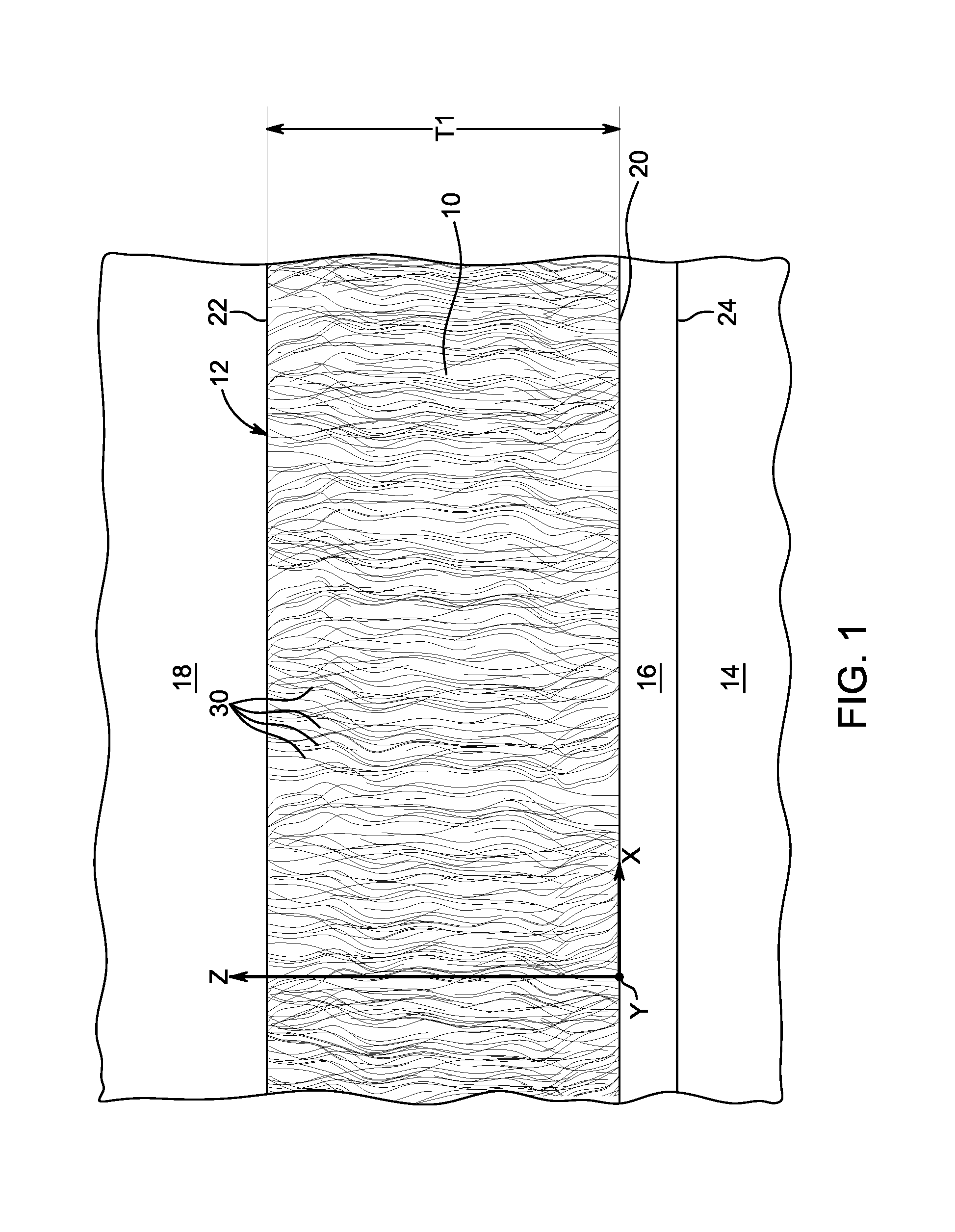
[0027] FIG. 1 is a cross-sectional view of exemplary batting incorporated in an exemplary insulative article and being utilized by a user according to the present disclosure.
[0028] FIG. 2 is a top view the exemplary batting and exemplary insulative article of FIG. 1.
[0029] FIG. 3 is a cross-sectional photograph of exemplary batting according to the present disclosure.
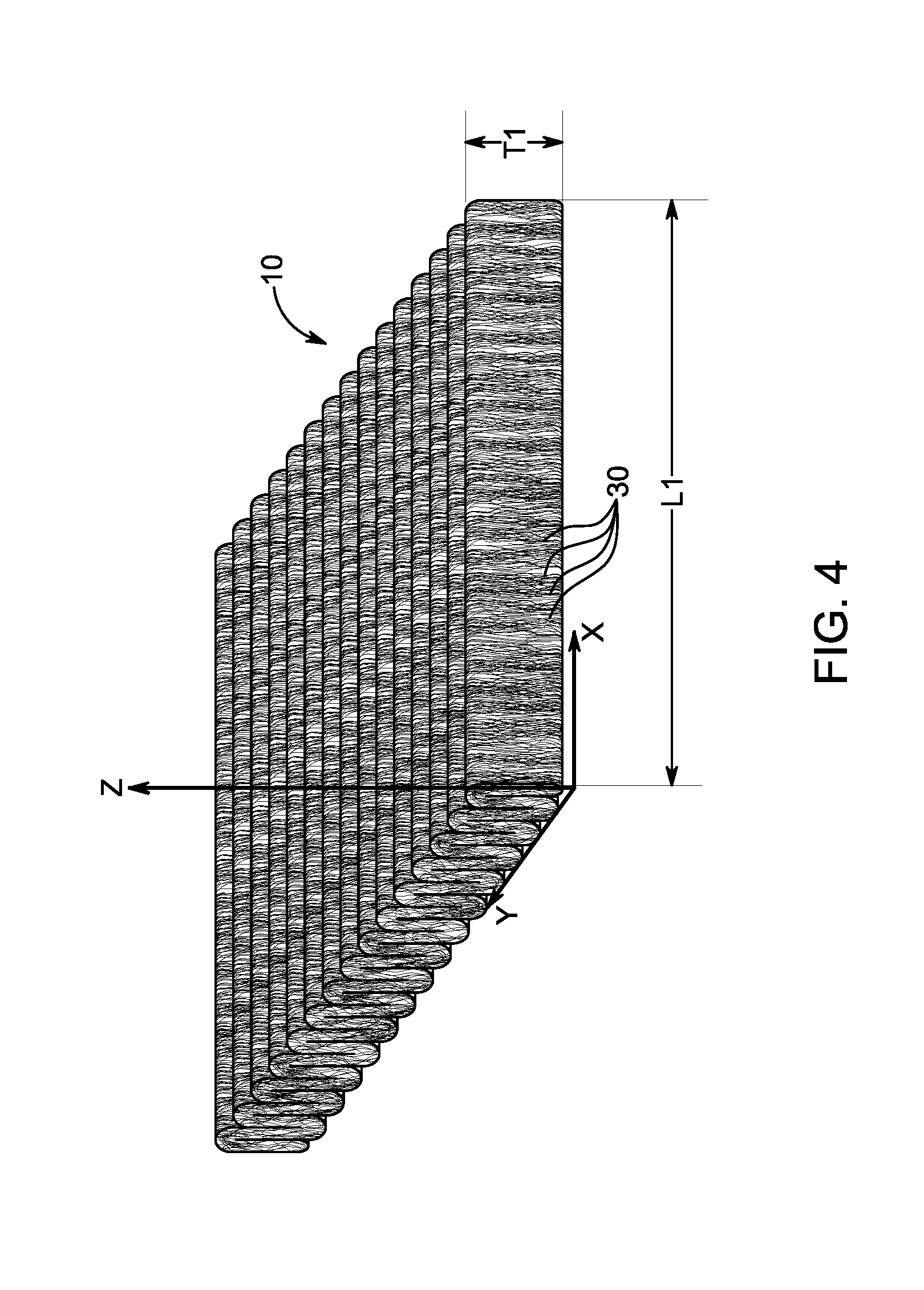
[0030] FIG. 4 is an elevational perspective view of exemplary batting being formed according to the present disclosure.
[0031] FIGS. 5 and 6 are side views of an exemplary functional fiber in un-activated and activated states of batting according to the present disclosure.
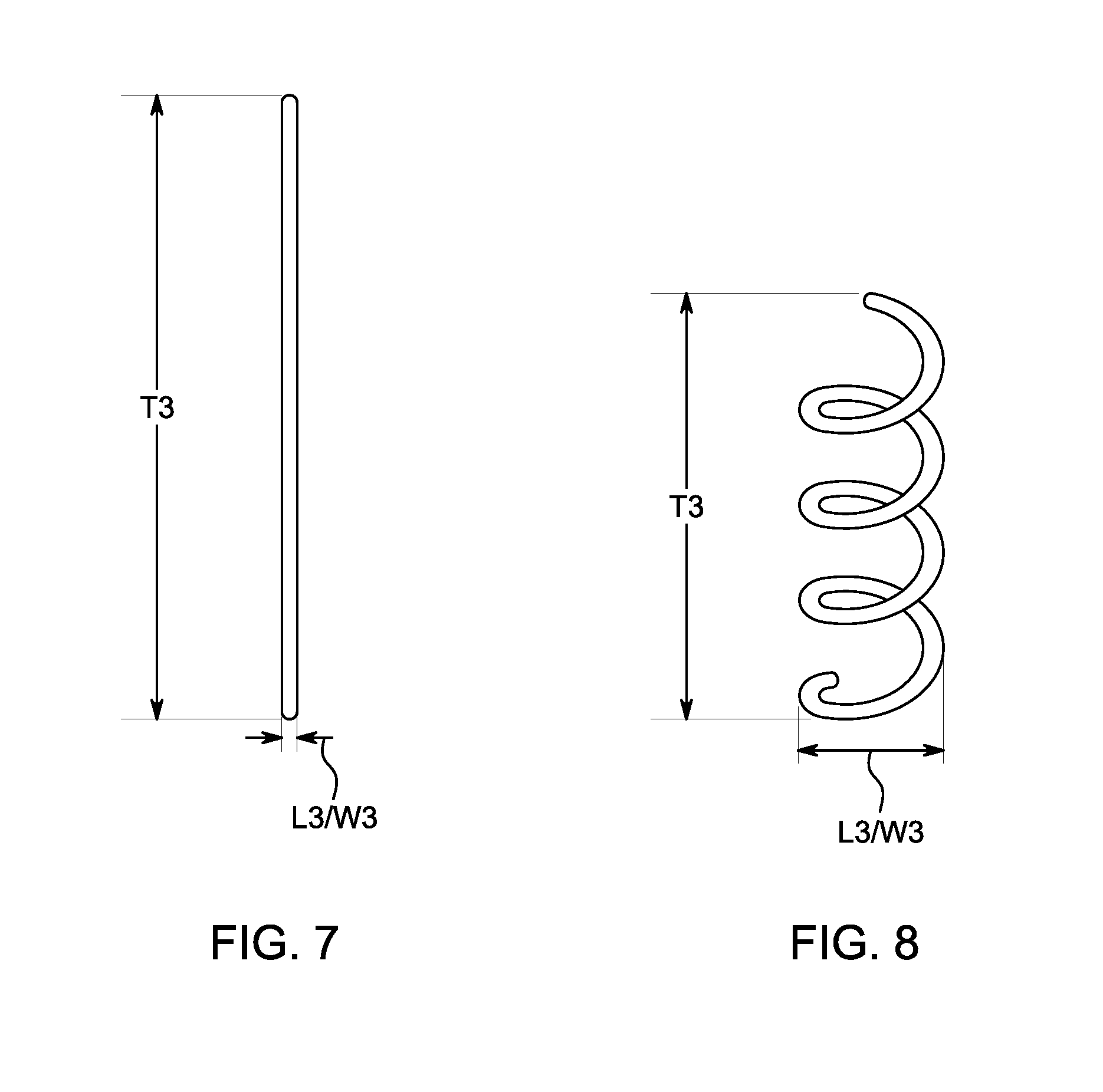
[0032] FIGS. 7 and 8 are side views of another exemplary functional fiber in un-activated and activated states of batting according to the present disclosure.
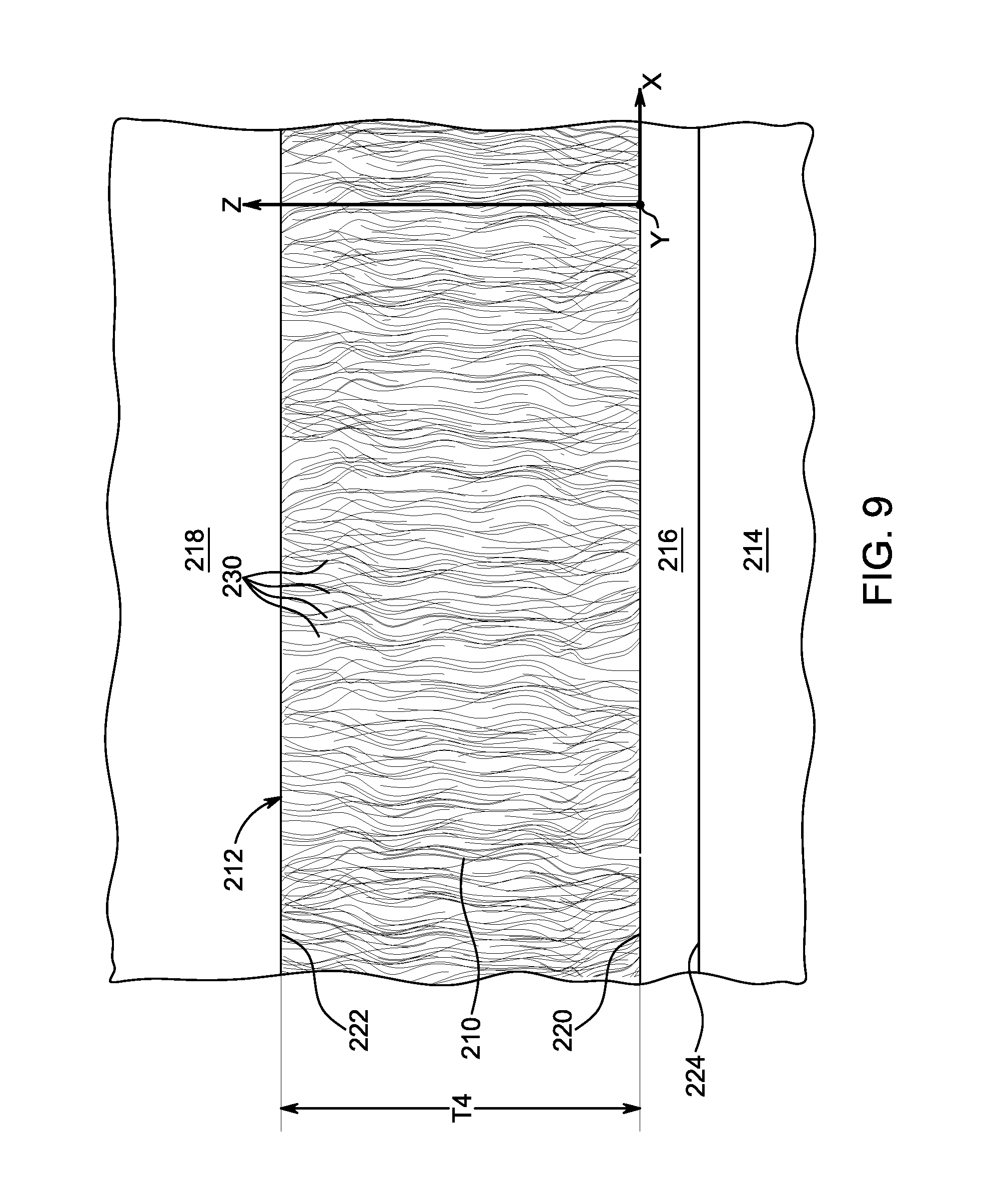
[0033] FIGS. 9 and 10 are cross-sectional views of exemplary batting in un-activated and activated states incorporated in an exemplary insulative article and being utilized by a user according to the present disclosure.
DETAILED DESCRIPTION OF THE INVENTION
[0034] Aspects of the present disclosure and certain features, advantages, and details thereof are explained more fully below with reference to the non-limiting embodiments illustrated in the accompanying drawings. Descriptions of well-known materials, fabrication tools, processing techniques, etc., are omitted so as to not unnecessarily obscure the present disclosure in detail. It should be understood, however, that the detailed description and the specific example(s), while indicating embodiments of the present disclosure, are given by way of illustration only, and are not by way of limitation. Various substitutions, modifications, additions and/or arrangements within the spirit and/or scope of the underlying inventive concepts will be apparent to those skilled in the art from this disclosure.
[0035] The present disclosure provides for non-woven batting, processes of making the batting, and insulative articles including the batting, that self-regulate or automatically regulate their insulative quality, at least to a certain extent with respect to at least one environmental variable, based on one or more change in environmental conditions interacting with at least a portion of the batting (and thereby interacting with at least a portion of the article including the batting). As shown in FIG. 1, in some embodiments the batting 10 of the present disclosure may self-regulate its insulative quality, at least to a certain extent with respect to at least one environmental variable, based on at least one change in environmental conditions in a micro climate 16 between an outer surface 24 of a user's body or person 14 and an interior side or surface 20 of the batting 10 (or an article 12 including the batting 10). The micro climate 16 may thereby interact with at least a portion of the batting 10 (and/or the article 12 including and the batting) via the interior side 20. The batting 10 may self-regulate its insulate quality or effectiveness in resisting the flow of at least one environmental variable of the micro climate 16 through the batting 10 from the interior side 20 to an exterior side 22 (e.g., in the z direction) thereof and, thereby, out of the micro climate 16 based on at least one change of a parameter of the micro climate 16. The batting 10 may likewise self-regulate its insulate quality or effectiveness in resisting the flow of at least one environmental variable of an exterior environment 18 interacting with the exterior surface 22 of the batting 10 through the batting 10 (e.g., in the z direction) and, thereby, into the micro climate 16 (e.g., based on at least one change in environmental conditions in the micro climate 16).
[0036] As a non-limiting example of at least one environmental variable that may be resisted differently or regulated by the batting 10 in response to at least one environmental change of the micro climate 16, the batting 10 may self-regulate its insulative quality or effectiveness with respect to heat and/or moisture based on moisture changes within the micro climate 16. In such an embodiment, the batting 10 may thereby self-regulate the rate at which heat or temperature and/or moisture of the micro climate 16 flows through the batting 10 and out of the micro climate 16, and thereby the temperature and/or moisture of the micro climate 16 itself, based on changes in humidity/moisture within the micro climate 16. For example, the batting 10 may decrease its insulative effectiveness to temperature and/or moisture in response to an increase in moisture within the micro climate 16 to allow a greater amount or rate of heat and/or moisture to flow therethrough (and thereby out of the micro climate 16) to cool and/or dry the micro climate 16 and, thereby, the user 14. The greater then the increase in moisture within the micro climate 16, the greater the batting 10 may decrease its insulative effectiveness to temperature and/or moisture. Similarly, the batting 10 may increase its insulative effectiveness to temperature and/or moisture (e.g., from a previous increased effectiveness) in response decreases in moisture within the micro climate 16 to resist a greater amount or rate of heat and/or moisture to flow therethrough (and thereby out of the micro climate 16) to provide a comfortable or desired temperature and/or moisture level or range to the user 14. The greater then the decrease in moisture within the micro climate 16, the greater the batting 10 may increase its insulative effectiveness to temperature and/or moisture. In this way, the batting 10 of the present disclosure may react to the moisture within the micro climate 16, which may directly or indirectly result from the amount of moisture emitted by a user 14 of an article 12 containing the batting 10, and may indicate that the body temperature of the user 14 needs to cool down, by regulating or adapting the temperature and/or moisture resistance of the batting 10.
[0037] In some embodiments, the batting 10 may be configured, as explained further below, to regulate its insulative effectiveness to temperature and/or moisture based on corresponding changes in moisture levels or humidity in the micro climate 16 only when above a pre-determined threshold, set point or maximum humidity level. For example, in some embodiments the batting 10 may be configured to regulate its insulative effectiveness to temperature and/or moisture based on changes in moisture levels or humidity in the micro climate 16 only when above a threshold humidity level (e.g., a humidity level deemed comfortable). The batting 10 may also have a self-regulating range of moisture levels (i.e., a range of moisture levels from the threshold humidity level) at which the insulative effectiveness is regulated.
[0038] As shown in the cross-sectional view of the illustration of FIG. 1, the top view of the illustration of FIG. 2, and the cross-sectional view of the photograph of FIG. 3, the batting 10 of the present disclosure may be formed of non-woven elongate fibers 30 that extend substantially or primarily vertically or along the z-axis of the batting 10 (i.e., the third dimension of the batting 10). As shown in FIG. 1, the z-axis of the batting 10 may correspond or extend parallel to the thickness T1 direction of the batting 10 extending between the interior surface 20 and the exterior surface 22 of the batting 10. As noted above, the batting 10 may be positioned within or otherwise utilized with an insulative article 12. The plurality of fibers 30 of the batting 10 may be arranged or positioned (rather than extend) along the x axis (e.g., a length L1 direction) and the y axis (e.g., a width direction W1), as shown in FIGS. 1 and 2.
[0039] The fibers 30 of the batting 10 may be substantially elongate, and may extend substantially parallel to or be aligned with the z-axis (along the thickness T1 direction) of the batting 10, as shown in FIG. 1. The fibers 30 may thereby extend, at least partially, between the interior surface 20 and the exterior surface 22 of the batting 10. The fibers 30 may be substantially smaller along the x-axis (the length L1 direction) and the y-axis (the width W1 direction) than the z-axis (the thickness T1 direction). The fibers 30 of the batting 10 may thus extend predominately along the z-axis (the thickness T1 direction). The fibers 30 of the batting 10 may thereby be referred to as vertically oriented.
[0040] The fibers 30 may extend at least along a portion of the thickness T1 of the batting 10 and be oriented substantially parallel to or along the z-axis, as shown in FIG. 1. In some embodiments, the batting 10 may include fibers 30 that extend along only a portion of the thickness T1 of the batting 10 and/or fibers 30 that traverse the entirety of the thickness T1 of the batting 10 at least once. For example, the batting 10 may include fibers 30 that extend along only a portion of the thickness T1 of the batting 10 in the z direction. Such fibers 30 may be fully positioned between and spaced from the interior surface 20 and the exterior surface 22 of the batting 10, or may extend from one of the interior surface 20 or the exterior surface 22. For example, a fiber 30 may extend from one of the interior surface 20 or the exterior surface 22 along the z direction (i.e., the thickness T1 direction) and only along a portion of the thickness T1 of the batting 10 (i.e., and not reach the other of the interior surface 20 or the exterior surface 22). As another example, a fiber 30 may extend from the interior of the thickness T1 of the batting 10 along the z-axis and to one of the interior surface 20 or the exterior surface 22, bend or curved back towards the other of the interior surface 20 or the exterior surface 22 therefrom, and extend along the z-axis through a portion of the thickness T1 of the batting 10.
[0041] The batting 30 may be formed via any process capable of forming the batting 10 with the vertical or z-axis orientated non-woven fibers 30. For example, the batting 30 may be formed via a vertical lapping process (sometimes referred to as Struto or V-lap process). In one non-limiting example, a plurality of differing fibers 30 may be opened and then blended together. The opened and blended fibers 30 may be parallelized into a non-woven, carded web layer via a carding machine and process. The non-woven web of fibers 30 (and optionally two or more web layers) may be carried on a conveyor from the carding machine and process to a vertical lapping device, such as a Struto.RTM. lapping device or V-lap .RTM. lapping device for example. The vertical lapping machine/process may fold the web back and forth in an accordion or serpentine manner along the z axis into a substantially uniform structure on a second conveyor, as illustrated in FIGS. 3 and 4. The web layer may bend back and forth along the z-axis such that the bends are relative smooth arcs or curved portions of the web layer and the fibers 30 themselves. In other embodiments, the bends may be formed by the web layer being folded over itself such that they are relatively sharp arcs or curved portions of the web layer and the fibers 30 themselves.
[0042] The folded or serpentine web may thereby extend along the z-axis and the x-axis, with the fibers 30 predominantly or primarily extending along the z-axis (i.e., height H1 direction), as shown in FIGS. 3 and 4. The folds may be compressed together, such as along the x-axis, to form a continuous batting structure with the vertically oriented fibers 30. The parallelized fibers 30 may thereby be arranged in a vertical position within the batting 10 giving the fibers 30 a three-dimensional, z-axis orientation, while being arranged or spaced along the x-axis and y-axis.
[0043] The batting structure with the vertically oriented fibers 30 may then be heated, and subsequently cooled such that at least some of the fibers 30 are bonded to other fibers 30. The batting structure with the vertically oriented fibers 30, or a portion thereof, may be heated via any mechanism. In one embodiments, the structure may be heated in a thermal bonding oven. The batting structure with the vertically oriented fibers 30 may be heated such that fibers 30 of adjacent passes or sections of the serpentine shape extending along the z-axis become bonded, such that batting 10 has structural integrity that imparts handleability of the batting 10 in sheet form. As explained further below, the blend of fibers 30 may include such a binder fiber that is configured bond to other fibers 30 when heated to relatively high temperatures and cooled. After bonding, the batting structure with the non-woven fibers 30 that are bonded and primarily vertically extending may be a permanent structure that can be further processed (e.g., slitting, cutting, winding, etc.) into the batting 10. In some embodiments, the batting 10 may be formed by a process flow including fiber blending, opening, carding, vertical lapping, bond (e.g., thermal bonding), slitting, cutting, and winding, or a combination thereof. The batting 10 may be incorporated into an insulative article in a myriad of differing ways.
[0044] Due to the vertical orientation of the fibers 30 (i.e., predominantly extending along the z-axis or thickness directions), the batting 10 may provide improved resiliency, compression resistance and recovery from compression, while still maintaining a light weight, as compared to batting with other fiber orientations. In addition to improved resiliency, compression resistance and recovery from compression, the batting 10 may have the ability to automatically or self-regulate its insulative quality, at least to a certain extent with respect to at least one environmental variable, based at least one change in environmental conditions interacting with the batting. An insulative article including the batting 10 can thereby be worn in a wider variety of environments and enhance the comfort of the user. In this way, the batting 10 (and thereby an insulative article including the batting 10) may provide dynamic comfort management to a user. For example, the batting 10 (and thereby an insulative article including the batting 10) may automatically regulate its temperature and/or moisture insulative quality in response to changes in humidity conditions in the micro climate between the batting 10 and a user. In such an example, the batting 10 may automatically regulate its temperature and/or moisture insulative quality in response to corresponding changes in humidity conditions in the micro climate between the batting 10 and a user by substantially changing its thickness T1 along the z-axis. As one or ordinary skill in the art would appreciate, the thickness T1 of the batting 10 extending along the z-axis may directly (or indirectly) effect the temperature and/or moisture insulative quality (e.g., resistance) of the batting 10.
[0045] As noted above, the fibers 30 making up the batting 10 may be a blend of differing fibers 30 (e.g., fibers of differing compositions and/or physical characteristics). In some embodiments of the batting 10, the blend of fibers 30 may be homogenously mixed, meaning the fiber mixture has a substantially uniform (i.e., 90-100% uniform) composition throughout the batting 10. In some embodiments, the blend of fibers 30 may include fibers of the same physical configurations or characteristics, such as the same lengths and/or deniers. Denier is a unit of measure defined as the weight in grams of 9000 meters of a fiber or yarn. It is a common way to specify the weight (or size) of the fiber or yarn. For example, polyester fibers that are 1.0 denier typically have a diameter of approximately 10 micrometers. Micro-denier fibers are those having a denier of 1.0 or less, while macro-denier fibers have a denier greater than 20.
[0046] In some other embodiments, the blend of fibers 30 may include fibers of differing physical configurations or characteristics. For example, the blend of fibers 30 may include fibers of differing lengths and/or deniers. In some embodiments, the blend of fibers 30 may include fibers with deniers within the range of about 0.5 D to about 0.8 D (e.g., 0.5 D, 0.6 D, 0.7 D or 0.8 D), including any and all ranges and subranges therein. In some embodiments, the blend of fibers 30 may include at least one type of fibers including a first denier, and at least one differing type of fibers (e.g., made from a differing material) including a second denier that is smaller or larger than the first denier. In some embodiments, the blend of fibers 30 may include at least one type of fibers including differing deniers. In some embodiments, the fibers 30 include at least some micro-denier fibers (e.g., fibers having a denier of 0.7 to 1.0 denier). In some embodiments, the fibers 30 include at least some macro-denier fibers (e.g., fibers having a denier of 1.1 to 8.0 denier). In some embodiments, the blend of fibers 30 may include micro-denier fibers and macro-denier fibers.
[0047] In some embodiments, the fibers 30 making up the blend may be staple fibers (i.e., fibers of standardized length). In some embodiments, the blend of fibers 30 may include fibers of differing staple lengths, such as within the range of about 12 mm to about 70 mm (e.g., 12 mm, 13 mm, 14 mm, 15 mm, 16 mm, 17 mm, 18 mm, 19 mm, 20 mm, 21 mm, 22 mm, 23 mm, 24 mm, 25 mm, 26 mm, 27 mm, 28 mm, 29 mm, 30 mm, 31 mm, 32 mm, 33 mm, 34 mm, 35 mm, 36 mm, 37 mm, 38 mm, 39 mm, 40 mm, 41 mm, 42 mm, 43 mm, 44 mm, 45 mm, 46 mm, 47 mm, 48 mm, 49 mm, 50 mm, 51 mm, 52 mm, 53 mm, 54 mm, 55 mm, 56 mm, 57 mm, 58 mm, 59 mm, 60 mm, 61 mm, 62 mm, 63 mm, 64 mm, 65 mm, 66 mm, 67 mm, 68 mm, 69 mm or 70 mm), including any and all ranges and subranges therein.
[0048] In some embodiments, the blend of fibers 30 may include at least one type of fibers including a first staple length, and at least one differing types of fibers (e.g., made from a differing material) including a second staple length that is shorter or longer than the first staple length. In some embodiments, the blend of fibers 30 may include at least one type of fibers including differing staple lengths. In some embodiments, the blend of fibers 30 may include differing types of fibers (e.g., made from a differing material) including the same denier but differing staple lengths. In some embodiments, the blend of fibers 30 may include differing types of fibers (e.g., made from a differing material) including the same staple length but differing deniers.
[0049] In some embodiments, the blend of fibers 30 may include fibers made from differing materials. For example, the blend of fibers 30 making up the batting 10 may include binder fiber made form a material that configures the fibers to bond to other fibers, as discussed above. In some embodiments, the blend of fibers 30 may include at least about 10% binder fiber. However, in some other embodiments the blend of fibers 30 making up the batting 10 may be void of a binder fiber configured to melt and bond to other fibers 30 in the batting 10. In such an embodiment, the fibers 30 may still none the-less be sufficiently adhered or bonded to one another so as to form a discrete batting structure that has structural integrity and is capable of being handled and used as-is, without falling apart or otherwise compromising the structural integrity of the batting so as to make it unfit for end use. For example, in some embodiments a resin may be used to adhere the fibers 30 together. In some embodiments, a resin including a cross-linked copolymer of butyl acrylate and methyl methacrylate may be utilized to adhere fibers 30 together, rather than or in addition to the use of binder fibers and heat.
[0050] In some embodiments, the blend of fibers 30 making up the batting 10 may include siliconized fibers (as described further below), may be void of siliconized fibers, or may include both siliconized fibers and non-siliconized fibers. Generally speaking, the fibers 30 may be crimped or uncrimped. Various crimps, including spiral and standard (e.g., planar) crimp, are known in the art. In some embodiments, the blend of fibers 30 making up the batting 10 may include hollow fibers and/or conjugate, such as hollow conjugate fibers.
[0051] In some embodiments, the blend of fibers 30 may fibers that include a water repellent treatment. Durable water repellant (DWR) treatments are well known in the art, and provide water repellent properties to treated components. Persons having ordinary skill in the art are familiar with a variety of DWR treatments, any of which may optionally be used on fiber populations in connection with the present disclosure. In some embodiments, fibers 30 used in the inventive batting 10 (which may be referred to as DWR-treated fibers 30 or water repellant fibers 30) may have been treated with a polymer solution of zirconium acetate, which can impart durable water repellant properties while minimizing and/or avoiding negative effects on fiber performance. In some embodiments, fibers 30 treated with a durable water repellant may be treated with a water-repellant, bacterial-resistant, low friction cured zirconium acetate finish, such that the fibers have improved driability following washing and enhanced handle and resistance to clumping. An example of a zirconium acetate solution that may be used as a DWR treatment in connection with the present disclosure is disclosed in U.S. Pat. No. 4,537,594. In some embodiments, a fiber 30 treated with a durable water repellant may be treated in a wet bath or dry spraying process. In some embodiments, the treatment includes a surface energy modification technique, which, as is known in the art, may include, e.g., plasma treatment. Such treatments or processes are explained in U.S. Pat. Nos. 4,869,922, 5,262,208, 5,895,558, 6,416,633, 7,510,632, 8,309,033, and U.S. Pat. No. 8,298,627.
[0052] The blend of fibers 30 making up the batting 10 may include fibers made from differing materials or the same material(s). In some embodiments, the blend of fibers 30 making up the batting 10 may include fibers made from virgin and/or post-consumer recycled polyester (which may be siliconized, may not be siliconized, or may include a combination of siliconized and non-siliconized fibers). In some embodiments, the blend of fibers 30 making up the batting 10 may include fibers made from at least one of poly(lactic acid) (PLA), polypropylene, polyurethane, nylon (e.g., nylon 6,6), poly(butyl acrylate) (PBA), acrylic, mod-acrylic, rayon, wool, alpaca, kapok or milkweed, or combinations thereof.
[0053] In some embodiments, the blend of fibers 30 may include synthetic fibers and natural fibers. In some embodiments, the blend of fibers 30 may be a mixture of synthetic fibers. Persons having ordinary skill in the art are readily familiar with many synthetic fibers, and it is well within their purview to select an appropriate synthetic fiber for use in inventive batting 10 embodiments depending on desired properties of the batting and/or article within which it is intended to be employed. Embodiments of the inventive batting 10 can may include any synthetic fiber known in the art as being conducive to the preparation of textile materials. In some embodiments, nonexclusive synthetic fibers 30 that may be used to form the batting 10 are selected from nylon, polyester, polypropylene, polylactic acid (PLA), poly(butyl acrylate) (PBA), polyamide, acrylic, acetate, polyolefin, nylon, rayon, lyocell, aramid, spandex, viscose, and modal fibers, and combinations thereof. In particular embodiments, synthetic fibers may be polyester fibers. For example, in some embodiments, the polyester is selected from poly(ethylene terephthalate), poly(hexahydro-p-xylylene terephthalate), poly(butylene terephthalate), poly-1,4-cyclohexelyne dimethylene (PCDT) and terephthalate copolyesters in which at least 85 mole percent of the ester units are ethylene terephthalate or hexahydro-p-xylylene terephthalate units. In a particular embodiment, the polyester is polyethylene terephthalate. In some embodiments, the synthetic fibers are virgin fibers. In some embodiments, the synthetic fibers are recycled fibers (e.g., recycled polyester fibers).
[0054] The blend of fibers 30 may be a mixture with 0 to 100 wt % synthetic fibers, for example, 0, 1, 2, 3, 4, 5, 6, 7, 8, 9, 10, 11, 12, 13, 14, 15, 16, 17, 18, 19, 20, 21, 22, 23, 24, 25, 26, 27, 28, 29, 30, 31, 32, 33, 34, 35, 36, 37, 38, 39, 40, 41, 42, 43, 44, 45, 46, 47, 48, 49, 50, 51, 52, 53, 54, 55, 56, 57, 58, 59, 60, 61, 62, 63, 64, 65, 66, 67, 68, 69, 70, 71, 72, 73, 74, 75, 76, 77, 78, 79, 80, 81, 82, 83, 84, 85, 86, 87, 88, 89, 90, 91, 92, 93, 94, 95, 96, 97, 98, 99, or 100 wt %, including any and all ranges and subranges therein (e.g., 10 to 100 wt %, 30 to 100 wt %, 51 to 100 wt %, 40 to 90 wt %, 20 to 80 wt %, etc.). In some embodiments, the blend of fibers 30 includes greater than 50, 55, 60, 65, 70, or 75 wt % synthetic fiber.
[0055] In some embodiments, the synthetic fibers of the blend of fibers 30 may be siliconized fibers. The term "siliconized" means that the fiber is coated with a silicon-comprising composition (e.g., a silicone). Siliconization techniques are well known in the art, and are described, e.g., in U.S. Pat. No. 3,454,422. The silicon-comprising composition may be applied using any method known in the art, e.g., spraying, mixing, dipping, padding, etc. The silicon-comprising (e.g., silicone) composition, which may include an organosiloxane or polysiloxane, bonds to an exterior portion of the fiber. In some embodiments, the silicone coating is a polysiloxane such as a methylhydrogenpolysiloxane, modified methylhydrogenpolysiloxane, polydimethylsiloxane, or amino modified dimethylpolysiloxane. As is known in the art, the silicon-comprising composition may be applied directly to the fiber, or may be diluted with a solvent as a solution or emulsion, e.g. an aqueous emulsion of a polysiloxane, prior to application. Following treatment, the coating may be dried and/or cured. As is known in the art, a catalyst may be used to accelerate the curing of the silicon-comprising composition (e.g., polysiloxane containing Si--H bonds) and, for convenience, may be added to a silicon-comprising composition emulsion, with the resultant combination being used to treat the synthetic fiber. Suitable catalysts include iron, cobalt, manganese, lead, zinc, and tin salts of carboxylic acids such as acetates, octanoates, naphthenates and oleates. In some embodiments, following siliconization, the fiber may be dried to remove residual solvent and then optionally heated to between 65.degree. and 200.degree. C. to cure.
[0056] In the blend of fibers 30, 0 to 100 wt % of the fibers may be siliconized fibers, for example, 0, 1, 2, 3, 4, 5, 6, 7, 8, 9, 10, 11, 12, 13, 14, 15, 16, 17, 18, 19, 20, 21, 22, 23, 24, 25, 26, 27, 28, 29, 30, 31, 32, 33, 34, 35, 36, 37, 38, 39, 40, 41, 42, 43, 44, 45, 46, 47, 48, 49, 50, 51, 52, 53, 54, 55, 56, 57, 58, 59, 60, 61, 62, 63, 64, 65, 66, 67, 68, 69, 70, 71, 72, 73, 74, 75, 76, 77, 78, 79, 80, 81, 82, 83, 84, 85, 86, 87, 88, 89, 90, 91, 92, 93, 94, 95, 96, 97, 98, 99, or 100 wt %, including any and all ranges and subranges therein (e.g., 20 to 95 wt %, 25 to 90 wt %, 30 to 90 wt %, 40 to 85 wt %, 51 to 90 wt %, etc.). In some embodiments, the siliconized fibers are polyethylene fibers.
[0057] In some embodiments, the blend of fibers 30 may include up to 15 wt % of particles or material that is different from the synthetic material that the synthetic fiber is primarily comprised of For example, in some embodiments, the synthetic fibers may include 0, 0.1, 0.2, 0.3, 0.4, 0.5, 0.6, 0.7, 0.8, 0.9, 1.0, 1.1, 1.2, 1.3, 1.4, 1.5, 1.6, 1.7, 1.8, 1.9, 2.0, 2.1, 2.2, 2.3, 2.4, 2.5, 2.6, 2.7, 2.8, 2.9, 3.0, 3.1, 3.2, 3.3, 3.4, 3.5, 3.6, 3.7, 3.8, 3.9, 4.0, 4.1, 4.2, 4.3, 4.4, 4.5, 4.6, 4.7, 4.8, 4.9, 5.0, 5.1, 5.2, 5.3, 5.4, 5.5, 5.6, 5.7, 5.8, 5.9, 6.0, 6.1, 6.2, 6.3, 6.4, 6.5, 6.6, 6.7, 6.8, 6.9, 7.0, 7.1, 7.2, 7.3, 7.4, 7.5, 7.6, 7.7, 7.8, 7.9, 8.0, 8.1, 8.2, 8.3, 8.4, 8.5, 8.6, 8.7, 8.8, 8.9, 9.0, 9.1, 9.2, 9.3, 9.4, 9.5, 9.6, 9.7, 9.8, 9.9, 10.0, 10.1, 10.2, 10.3, 10.4, 10.5, 10.6, 10.7, 10.8, 10.9, 11.0, 11.1, 11.2, 11.3, 11.4, 11.5, 11.6, 11.7, 11.8, 11.9, 12.0, 12.1, 12.2, 12.3, 12.4, 12.5, 12.6, 12.7, 12.8, 12.9, 13.0, 13.1, 13.2, 13.3, 13.4, 13.5, 13.6, 13.7, 13.8, 13.9, 14.0, 14.1, 14.2, 14.3, 14.4, 14.5, 14.6, 14.7, 14.8, 14.9, or 15.0 wt % of particles or material different from the synthetic material that the synthetic fiber is primarily comprised of, including any and all ranges and subranges therein. In some embodiments, said particles or material is comprised within (e.g., encapsulated within) a polymer matrix that represents the synthetic material of which the synthetic fiber is primarily comprised. In some embodiments, the synthetic fibers in the fiber mixture comprise aerogel fiber, as described in U.S. Provisional Application No. 62/256,374.
[0058] In some embodiments, the blend of fibers 30 forming the batting 10 includes natural fibers. For example, in some embodiments, the blend of fibers 30 includes one or more members selected from wool, cotton, tencel, kapok (cotton-like fluff obtained from seeds of a Kapok tree, which may optionally be further processed before use), flax, animal hair, silk, and down (e.g., duck or goose down).
[0059] The blend of fibers 30 may include 0 to 100 wt % natural fibers, for example, 0, 1, 2, 3, 4, 5, 6, 7, 8, 9, 10, 11, 12, 13, 14, 15, 16, 17, 18, 19, 20, 21, 22, 23, 24, 25, 26, 27, 28, 29, 30, 31, 32, 33, 34, 35, 36, 37, 38, 39, 40, 41, 42, 43, 44, 45, 46, 47, 48, 49, 50, 51, 52, 53, 54, 55, 56, 57, 58, 59, 60, 61, 62, 63, 64, 65, 66, 67, 68, 69, 70, 71, 72, 73, 74, 75, 76, 77, 78, 79, 80, 81, 82, 83, 84, 85, 86, 87, 88, 89, 90, 91, 92, 93, 94, 95, 96, 97, 98, 99, or 100 wt %, including any and all ranges and subranges therein (e.g., 0 to 50 wt %, 1 to 40 wt %, 5 to 25 wt %, 30 to 60 wt %, etc.). In some embodiments, the blend of fibers 30 includes less than 50, 40, 30, 20, or 10 wt % synthetic fiber.
[0060] The blend of fibers 30 may also include a plurality of at least one type of reactive or functional fibers. In some embodiments, the blend of fibers 30 may include at least about 15% functional fibers. In some embodiments, the blend of fibers 30 may include at least about 20% functional fibers. In some embodiments, the blend of fibers 30 may include within the range of about 15% to about 40% functional fibers, such as within the range of about 25% to about 40% functional fibers. The reactive fibers of the blend of fibers 30 may be configured to automatically or dynamically react to the environment around or interacting with them by correspondingly changing at least one characteristic or function thereof based on one or more change in the environment. The effect between the activated and un-activated state of the functional fibers may be reversible. At least one characteristic or variable of the environment (or climate) interacting with the functional fibers may thereby be a stimulus that causes the functional fibers to react by correspondingly changing at least one characteristic or function thereof accordingly. The reactive fibers may thereby be configured such that they have a particular behavior when exposed to an external predetermined stimulus or trigger. For example, reactive fibers with two chemically differing components may be activated by one or more stimulus. The reactive fibers may release heat, change shape (e.g., shrink or expand), change wicking ability, etc. in response to a change in at least one characteristic or variable of the environment (or climate) interacting with the functional fibers. Activating stimuli are not limited, and may be determined through the choice of fiber compositions, for example. In some embodiments, an activating stimulus may be moisture/humidity, temperature, light, pH, electrical current, force field, microbes, or biological matter. When exposed to such stimulus (or stimuli), the functional/reactive fibers may thereby become active fibers that actively change at least one characteristic or function thereof correspondingly in response to the stimulus. The batting 10 may utilize such functional fibers as a portion of the vertically oriented non-woven fibers 30 to automatically or self-regulate the insulative quality of the batting 10, at least to a certain extent with respect to at least one environmental variable, based at least one change in environmental conditions interacting with the batting 10 (i.e., interacting with the functional fibers of the batting 10). An example of functional fibers that may be utilized to form the batting 10 with the present disclosure are disclosed in International Patent Application Publication No. WO/2013/186528. In some embodiments, the functional fibers may be INOTEK.TM. bi-component fibers sold by MMT Textiles Limited of the United Kingdom.
[0061] In some embodiments, the functional fibers may have a first configuration in an un-activated state, and in response to activation by changes in the external stimulus (e.g., above a minimum threshold) the fibers bend or twist to adopt a second, increased crimp or twist configuration relative to the first configuration. The degree of activation or movement of the fibers may be proportional to the amount of change of the external stimulus. Stated differently, the greater the change in the stimulus, the greater the fibers may crimp or twist.
[0062] The functional fibers may be arranged in a helix in the second configuration with a relatively decreased radius and pitch as respect to the first configuration. The functional fibers may be arranged in a helix in the first configuration (or otherwise crimped) or may be substantially linear or straight in the first configuration. The increase in twist in the second configuration as compared to the first configuration may allow for functional fibers that are relatively long and wide when un-activated and relatively short and narrow when activated. The functional fibers may move between the first and second configurations in proportion to the external stimulus, at least in a workable range. For example, the functional fibers may be configured to activate at a certain set-point or activation level of the external stimuli, and crimp or twist to the second configuration up to a certain set-point or maximum level of the external stimuli. In conditions between the activation and maximum levels of the external stimuli, the functional fibers may adopt a number of transitional configuration between the first and second configurations or shapes.
[0063] In some embodiments, the functional fibers may be made from a shape-memory material. The shape-memory material may include at least two components having differing physical reaction to the external stimulus. The components may be in any ratio range and may be arranged in any configuration (such as, for example, an eccentric or asymmetric configuration). The shape of the fibers and/or the arrangement of the components or portions of the fibers may affect the mechanical configuration reaction to the activation stimuli. Shape-memory materials are able to retain two or more shapes and transition between those shapes when triggered by an external or environmental stimulus. The activating external stimulus or trigger for the functional fibers may be determined, at least in part, by the chemistry of the material forming the fibers.
[0064] For example, the functional fibers may be configured such that the external stimulus is moisture/humidity. In such embodiments, the shape-memory material of the fibers may have a relatively quick rate of reacting to changes in humidity so that they quickly change from the first configuration or shape to the second configuration or shape. In some humidity-reactive functional fiber embodiments, the fibers may be made from at least two polymers as bi-component fibers. For example, a minimum of two polymers may be utilized to form humidity-reactive functional fibers, with the at least two polymers having different thermal shrinking properties, Young's modulus and/or moisture absorption properties. Humidity-reactive functional fibers may include a hygroscopic component or portion and a non-hygroscopic component or portion. For example, in one non-limiting exemplary embodiment the functional fibers may be co-extruded fibers with a circular cross-section comprising Nylon 6 as the hygroscopic component and polypropylene (PP) as the non-hygroscopic component in a ratio 70:30 Nylon:Polypropylene ratio in an eccentric sheath core configuration.
[0065] In humidity-reactive functional fiber embodiments where humidity is the external stimulus (i.e., the function fibers are configured to react to humidity/moisture as the external trigger), in an active state the fibers are in a humid environment and in the active or second configuration or shape, in an un-activated state the fibers are in a relatively drier environment and an un-activated or first configuration or state. In such embodiments, when exposed to humid conditions above the set-point or minimum humidity level, the functional fibers may proportionally or gradually shrink at least along their length (and, potentially, along their width) as the humidity increases. In some embodiments, the when exposed to humid conditions above the set-point or minimum humidity level, the humidity-reactive functional fibers may be more tightly twisted in an activated configuration as compared with dry conditions in the un-activated configuration, and more tightly twist or crimp as the humidity increases from the activation humidity level to the maximum humidity level. In some embodiments, the activation humidity level may be a level which is deemed uncomfortable to a user and/or a humidity level that indicates the user may want or need less thermal insulation, as described further below.
[0066] An example of a physical mechanism leading to at least proportional shortening of a functional fiber 50 according to the present disclosure, such as a humidity-reactive functional fiber, is shown in FIGS. 5 and 6. As shown in FIG. 5, the functional fiber 50 may include a crimp or helix configuration in the activated state (and, potentially, in the un-activated state). As discussed above, the crimp or helix of the functional fiber 50 may be a heat-set or otherwise formed during and/or after formation of the fiber 50. The crimp or helix of the functional fiber 50 may be measured by the number of bends of the fiber per unit length and the radius of the bends. For example, a functional fiber 50 with a fine crimp may have many bends of a relatively small radius, and a functional fiber 50 with a course crimp may have relatively fewer bends of a relatively larger radius. A helix crimp, as shown in FIGS. 5 and 6, may be described as a three-dimensional curve around an axis. The pitch of the helix is the length of one complete turn measured along the axis of the helix. A circular helix has a constant curvature and constant torsion.
[0067] FIG. 5 illustrates the humidity-reactive functional fiber 50 in or exposed to a relatively dry environment of a humidity or moisture level below the set-point or minimum humidity level of the fiber. Thus, FIG. 5 illustrates the humidity-reactive functional fiber 50 in its un-activated or first configuration or shape. In the un-activated state, the functional fiber 50 has an oblong form factor with a length T2 (e.g., along the z axis) substantially greater than the length L2 (e.g., along the x axis) and width W2 (e.g., along the y axis). Upon exposure to a humid or moist environment of a humidity or moisture level at or above the set-point or minimum humidity level of the humidity-reactive functional fiber 50, the crimp of the fiber 50 may increase as shown in FIG. 6. As shown in FIG. 6, upon exposure of the humidity-reactive functional fiber 50 to a humid environment of a humidity/moisture level at or above the set-point humidity level the number of bends per length may increase and the radius of the bends may decrease (i.e. the helix becomes tighter, the radius and pitch of the helix decreases). In this way, the humidity-reactive functional fiber 50 may become more substantially shorter along the z-axis (and potentially smaller along the x axis and the y axis). The crimp of the fiber 50 may increase proportionally with respect to the increase in humidity of the environment. Stated differently, the greater that the humidity of the environment increases, the greater the crimp of the fiber 50 may increase.
[0068] The increase in crimp or helix configuration of the functional fiber 50 may be effectuated by the bi-component nature or composition of the fiber 50. For example, the humidity-reactive functional fiber 50 may include a hygroscopic polymer or component that is selected to have less thermal shrinkage and to be less stiff than a non-hygroscopic polymer or component. During the crimping process of the functional fiber 50, the hygroscopic component may want or be urged to elongate. However, elongation of the hygroscopic component may be restricted by the non-hygroscopic component, which may result in the crimp or helix configuration or arrangement of the fiber 50. Similarly, when the functional fiber 50 is exposed to a humid environment of a humidity/moisture level at or above the set-point humidity level the hygroscopic component may want or be urged to further elongate. Again, elongation of the hygroscopic component may be restricted by the non-hygroscopic component, and the relatively stiffer non-hygroscopic component may cause the crimp or helix angle to tighten into the activated configuration, as shown in FIG. 6. As shown in comparison of FIGS. 5 and 6, the increase or tightening of the crimp or helix structure of the functional fiber 50 may result in a substantial decrease in the length T2 (e.g., along the z axis) of the fiber 50, and relatively smaller decreases in the length L2 (e.g., along the x axis) and width W2 (e.g., along the y axis) of the fiber 50. When the humid environment decreases from the increased humidity/moisture level, the fiber 50 may return to the un-activated configuration.
[0069] Another embodiment of a functional fiber 150, such as a humidity-reactive functional fiber 150, is shown in FIGS. 7 and 8. The functional fiber 150 of FIGS. 7 and 8 is substantially similar to the functional fiber 50 of FIGS. 5 and 6, and therefore the description herein to the functional fiber 50 of FIGS. 5 and 6 equally applies to the functional fiber 150 of FIGS. 7 and 8. The functional fiber 150 of FIGS. 7 and 8 differs from the functional fiber 50 of FIGS. 5 and 6 with respect to the un-activated configuration or state of the functional fiber 150. As shown in FIG. 7, in the un-activated configuration the functional fiber 150 may be substantially linear or straight, and in the activated configuration the functional fiber 150 may crimped or in a helix configuration. As described above, the humidity of the environment acting on the fiber 150 may be below the set-point humidity level such that the fiber 150 is in the straight un-activated configuration. When the humidity of the environment acting on the fiber 150 increases to at or above the set-point humidity level, a hygroscopic component of the fiber 150 may want or be urged to elongate. This elongation of the hygroscopic component may be restricted by a non-hygroscopic component of the fiber 150, and the relatively stiffer non-hygroscopic component may cause the fiber 150 to crimp or curl into the activated helix configuration as shown in FIG. 8. The linear-to-helix reconfiguration (e.g., twisting) of the fiber 150 (i.e., the un-activated and activated states) may substantially decrease the length T3 (e.g., along the z axis) of the fiber 150, as shown in FIGS. 7 and 8. In some embodiments, the linear-to-helix reconfiguration of the fiber 150 may slightly increase the length L3 (e.g., along the x axis) and width W3 (e.g., along the y axis) of the fiber 150. In this way, the bends or twists of the fiber 150 may increase the travel of the fiber 150 in the length L3 and width W3 directions, and thereby decrease the length L3 of the fiber 150.
[0070] The batting of the present disclosure may utilize the functional fibers to self-regulate or automatically regulate its insulative quality, at least to a certain extent with respect to at least one environmental variable, based on one or more change in environmental conditions interacting with at least a portion of the batting (and thereby interacting with at least a portion of an article including the batting). As discussed above, the batting may be configured such that the blend of fibers making up the batting are substantially vertically oriented along the thickness or z axis of the batting. As also explained above, the blend of fibers making up the batting may include functional fibers that proportionally vary length between un-activated and activated states based on changes in an environmental stimulus. The batting may thereby utilize the vertically-aligned, length-varying functional fibers to effectuate variations in the thickness of the batting, which effectuates proportional changes in the insulative quality of the batting.
[0071] An example of such a self-regulating batting 210 is shown in FIGS. 9 and 10. The batting 210 may be incorporated in an article 212 that is worn or otherwise utilized by a user 214 for insulative purposes, as shown in FIGS. 9 and 10. As discussed above and shown in FIGS. 9 and 10, a micro climate 216 may exist between an outer surface 224 of the article 214 and an interior side or surface 220 of the batting 210 (or an article 212 including the batting 210). The micro climate 216 may thereby interact with at least a portion of an interior side 220 of the batting 210, and the batting 210 may self-regulate its insulate quality or effectiveness in resisting the flow of at least one environmental variable of the micro climate 216 through the batting 210 from the interior side 220 to an exterior side 222 (e.g., in the z direction) thereof based on changes in at least one environmental variable of the micro climate 216, and, thereby, out of the micro climate 216.
[0072] As a non-limiting example of at least one environmental variable that may be resisted differently by the batting 210 in response to at least one environmental change of the micro climate 216, the batting 210 may self-regulate its insulative quality or effectiveness with respect to heat and/or moisture based on humidity/moisture changes within the micro climate 216. In such an embodiment, the batting 210 may thereby self-regulate the rate at which heat and/or moisture of the micro climate 216 flows or travels through the batting 210 and out of the micro climate 216 based on the humidity/moisture within the micro climate 216. For example, the batting 216 may decrease its insulative effectiveness to temperature and/or moisture in response to an increase in moisture within the micro climate 216 above a defined threshold humidity level to allow a greater amount or rate of heat and/or moisture to flow therethrough and out of the micro climate 216 to cool and/or dry the micro climate 216 and, thereby, the user 214. Similarly, the batting 210 may increase its insulative effectiveness to temperature and/or moisture (e.g., from a previous increased effectiveness) in response to a decrease in moisture therefrom within the micro climate 216 to resist a greater amount or rate of heat and/or moisture to flow therethrough and thereby out of the micro climate 216. It is noted that when a user 214 initially wears or otherwise utilizes the article 214/batting 210, the conditions of the micro climate 216 may initially be substantially similar to the conditions of the environment about the user 214. In this way, the micro climate 216 may change from the exterior environmental conditions based on any heat and/or moisture emitted by the user 214 during use, and the batting 210 may react thereto to regulate its insulative effectiveness accordingly. The article 212 and/or batting 210 may include a layer or member that prevents moisture from interacting with the batting 210 other than via the micro climate 216. In this way, the article 212 and/or the batting 210 may be configured to ensure the moisture level of the micro climate 216 controls the thickness regulation, and thereby the regulation of the insulative effectiveness to temperature and/or moisture, of the batting 210.
[0073] As shown in FIGS. 9 and 10, the batting 216 may decrease its insulative effectiveness to temperature and/or moisture in response to an increase in moisture within the micro climate 216 above a defined threshold humidity level by decreasing its thickness along the z axis from a first thickness T4 to a second thickness T5 that is less than the first thickness T4 to allow a greater amount or rate of heat and/or moisture to flow therethrough and out of the micro climate 216 to cool and/or dry the micro climate 216 and, thereby, the user 214. The greater thickness T4 of the batting 210 along the z axis in the un-activated state (FIG. 9) as compared to the thinner thickness T5 in the activated state (FIG. 10) provides a greater insulative effectiveness to temperature and/or moisture. Likewise, the thinner thickness T5 of the batting 210 along the z axis in the activated state includes as compared to the greater thickness T4 in the un-activated state provides a reduced insulative effectiveness to temperature and/or moisture. In this way, the batting 210 of the present disclosure may react to the moisture within the micro climate 216 (e.g., when above a threshold moisture level), which may directly or indirectly result from the amount of moisture emitted by a user 214 of an article 212 containing the batting 210, by changing the thickness of the batting 210 along the z axis to regulate or adapt the temperature and/or moisture resistance of the batting 210. The degree of the change in thickness of the batting 210 may be proportional or depend upon the degree of the change in humidity/moisture of the micro climate 216--the greater the increase in humidity the thinner the batting 210 may become.
[0074] The batting 210 may change the thickness of the batting 210 along the z axis to regulate or adapt the temperature and/or moisture resistance of the batting 210 via the functional fibers. As discussed above, the functional fibers of the fibers 230 making up the batting 210 may proportionally change in length in response to changes in humidity or moisture level of the environment interacting or surrounding the fibers 230/batting 210, such as the moisture level of the micro climate 216. For example, the functional fibers of the fibers 230 making up the batting 210 may crimp or helix, or increase in crimp or helix tightness, from an un-activated shape to an activated state in response to an increase in the humidity or moisture level of the micro climate 216 above a above a defined threshold humidity level. The crimp, or increase in crimp, may effectuate a decrease in the length of the functional fibers, as discussed above. The crimp or helix may tighten as the moisture level of the micro climate 216 increases to gradually decrease the length of the fibers.
[0075] As the functional fibers may be integrated and/or bonded to the other fibers of the blend of fibers 230 making up the batting 210 and may be oriented substantially vertically along the z axis, the "shrinking" and "growing" functional fibers may act to decrease and increase the thickness T4/T5 of the batting 210 along the z axis, respectively, and thereby decrease and increase the insulative effectiveness of the batting 210 with respect to temperature and/or moisture proportionally in response to variations in the humidity/moisture within the micro climate 215. The amount of change in insulative effectiveness of the batting 210 with respect to temperature and/or moisture may depend upon the configuration of the functional fibers, the amount of functional fibers in the blend of fibers 230 comprising the batting 210, and/or the configuration of the non-functional fibers in the blend of fibers 230, for example. Similarly, the amount of change in thickness of the batting 210 with respect to a particular change in humidity may depend upon the configuration of the functional fibers, the amount of functional fibers in the blend of fibers 230 comprising the batting 210, and/or the configuration of the non-functional fibers in the blend of fibers 230, for example. In some embodiments, the change in thickness of the batting from the first thickness T4 in the un-activated state (FIG. 9) as compared to the second thickness T5 in a fully activated state (FIG. 10) may be at least about 10%. In some embodiments, the change in thickness of the batting from the first thickness T4 in the un-activated state (FIG. 9) as compared to the second thickness T5 in a fully activated state (FIG. 10) may be at least about 15%. In some embodiments, the change in thickness of the batting from the first thickness T4 in the un-activated state (FIG. 9) as compared to the second thickness T5 in a fully activated state (FIG. 10) may be at least about 20%. In some embodiments, the change in thickness of the batting from the first thickness T4 in the un-activated state (FIG. 9) as compared to the second thickness T5 in a fully activated state (FIG. 10) may be within the range of about 15% to about 40%. In some embodiments, the change in thickness of the batting from the first thickness T4 in the un-activated state (FIG. 9) as compared to the second thickness T5 in a fully activated state (FIG. 10) may be within the range of about 25% to about 40%. The change in thickness of the batting 210 may affect the clo of the batting 210. For example, as the thickness of the batting decreases, the clo may correspondingly decrease. The amount of change in clo of the batting 210 may depend upon the configuration of the functional fibers, the amount of functional fibers in the blend of fibers 230 comprising the batting 210, and/or the configuration of the non-functional fibers in the blend of fibers 230, for example.
EXAMPLES
[0076] The present disclosure will now be illustrated, but not limited, by reference to the specific embodiment described in the following example.
Example 1
[0077] A fiber mixture is prepared by mixing the following: [0078] At least 15% 2.2 denier, 51 mm low melt binder staple fiber; [0079] At least 25% 2.0 denier, 51 mm moisture-activated functional staple fiber; [0080] At least 20% 1.4 denier, 51 mm siliconized polyester staple fiber; and [0081] At least 20% 7.0 denier, 64 mm siliconized polyester hollow conjugate staple fiber.
[0082] After being mixed/blended, the fiber mixture is then processed into web form on a traditional carding machine to form a nonwoven web. The web is then sent through a vertical-lapper in order to vertically orient the fibers along the z axis and to achieve a thickness and weight. The batting structure may then be heated to effectuate bonding of the binder fiber and to form batting.
[0083] The functional fibers are configured such that the defined threshold humidity level is about 60%, and the maximum reactive humidity level is about 98%. The batting is therefore active when exposed to changes in environment between 60% and 98% humidity (i.e., the batting includes an activation zone between 60% and 98% humidity). The batting is formed such that in an un-activated state (i.e., in an environment less than 60% humidity), the batting includes a thickness of about 19.6 mm and a weight of about 105 g/m2 (3.09 oz/yd2). The un-activated batting includes a total clo of about 2.453 and a clo/oz/yd2 of about 0.794 in the un-activated state. In the fully activated state (i.e., exposed to 98% humidity or greater), the batting includes a thickness of about 14.9 mm (a decrease in thickness along the z axis of about 24%). The activated batting includes a total clo of about 1.864 and a clo/oz/yd2 of about 0.603. The weight between the un-activated and fully activated states of the batting remains substantially the same.
[0084] The terminology used herein is for the purpose of describing particular embodiments only and is not intended to be limiting of the present disclosure. As used herein, the singular forms "a", "an" and "the" are intended to include the plural forms as well, unless the context clearly indicates otherwise. It will be further understood that the terms "comprise" (and any form of comprise, such as "comprises" and "comprising"), "have" (and any form of have, such as "has" and "having"), "include" (and any form of include, such as "includes" and "including"), "contain" (and any form contain, such as "contains" and "containing"), and any other grammatical variant thereof, are open-ended linking verbs. As a result, a method or article that "comprises", "has", "includes" or "contains" one or more steps or elements possesses those one or more steps or elements, but is not limited to possessing only those one or more steps or elements. Likewise, a step of a method or an element of an article that "comprises", "has", "includes" or "contains" one or more features possesses those one or more features, but is not limited to possessing only those one or more features.
[0085] As used herein, the terms "comprising," "has," "including," "containing," and other grammatical variants thereof encompass the terms "consisting of" and "consisting essentially of."
[0086] The phrase "consisting essentially of" or grammatical variants thereof when used herein are to be taken as specifying the stated features, integers, steps or components but do not preclude the addition of one or more additional features, integers, steps, components or groups thereof but only if the additional features, integers, steps, components or groups thereof do not materially alter the basic and novel characteristics of the claimed compositions or methods.
[0087] All publications cited in this specification are herein incorporated by reference as if each individual publication were specifically and individually indicated to be incorporated by reference herein as though fully set forth.
[0088] Subject matter incorporated by reference is not considered to be an alternative to any claim limitations, unless otherwise explicitly indicated.
[0089] Where one or more ranges are referred to throughout this specification, each range is intended to be a shorthand format for presenting information, where the range is understood to encompass each discrete point within the range as if the same were fully set forth herein.
[0090] While several aspects and embodiments of the present disclosure have been described and depicted herein, alternative aspects and embodiments may be affected by those skilled in the art to accomplish the same objectives. Accordingly, this disclosure and the appended claims are intended to cover all such further and alternative aspects and embodiments as fall within the true spirit and scope of the present disclosure.
* * * * *
D00000
D00001
D00002
D00003
D00004
D00005
D00006
D00007
D00008
XML
uspto.report is an independent third-party trademark research tool that is not affiliated, endorsed, or sponsored by the United States Patent and Trademark Office (USPTO) or any other governmental organization. The information provided by uspto.report is based on publicly available data at the time of writing and is intended for informational purposes only.
While we strive to provide accurate and up-to-date information, we do not guarantee the accuracy, completeness, reliability, or suitability of the information displayed on this site. The use of this site is at your own risk. Any reliance you place on such information is therefore strictly at your own risk.
All official trademark data, including owner information, should be verified by visiting the official USPTO website at www.uspto.gov. This site is not intended to replace professional legal advice and should not be used as a substitute for consulting with a legal professional who is knowledgeable about trademark law.