Metal Hollow Fiber Electrode
KAS; Recep ; et al.
U.S. patent application number 15/778864 was filed with the patent office on 2019-09-05 for metal hollow fiber electrode. This patent application is currently assigned to Universiteit Twente. The applicant listed for this patent is Universiteit Twente. Invention is credited to Nieck Edwin BENES, Patrick DE WIT, Recep KAS, Guido MUL.
| Application Number | 20190271089 15/778864 |
| Document ID | / |
| Family ID | 57681708 |
| Filed Date | 2019-09-05 |


| United States Patent Application | 20190271089 |
| Kind Code | A1 |
| KAS; Recep ; et al. | September 5, 2019 |
METAL HOLLOW FIBER ELECTRODE
Abstract
The invention is directed to a metal hollow fiber electrode, to a method of electrolyzing carbon dioxide in an aqueous electrochemical cell, to a method of converting carbon dioxide, to a method of preparing a metal hollow fiber, to a use of a metal hollow fiber electrode. The metal hollow fiber electrode comprises aggregated copper particles forming an interconnected three-dimensional porous structure, wherein said metal comprises copper.
| Inventors: | KAS; Recep; (Enschede, NL) ; DE WIT; Patrick; (Enschede, NL) ; BENES; Nieck Edwin; (Enschede, NL) ; MUL; Guido; (Enschede, NL) | ||||||||||
| Applicant: |
|
||||||||||
|---|---|---|---|---|---|---|---|---|---|---|---|
| Assignee: | Universiteit Twente Enschede NL |
||||||||||
| Family ID: | 57681708 | ||||||||||
| Appl. No.: | 15/778864 | ||||||||||
| Filed: | November 24, 2016 | ||||||||||
| PCT Filed: | November 24, 2016 | ||||||||||
| PCT NO: | PCT/NL2016/050826 | ||||||||||
| 371 Date: | May 24, 2018 |
Related U.S. Patent Documents
| Application Number | Filing Date | Patent Number | ||
|---|---|---|---|---|
| 62259089 | Nov 24, 2015 | |||
| Current U.S. Class: | 1/1 |
| Current CPC Class: | C25B 11/035 20130101; C25B 11/0415 20130101; C25B 3/04 20130101; C25B 1/00 20130101; C25B 11/02 20130101; C25B 11/0447 20130101 |
| International Class: | C25B 11/02 20060101 C25B011/02; C25B 1/00 20060101 C25B001/00; C25B 11/04 20060101 C25B011/04; C25B 11/03 20060101 C25B011/03; C25B 3/04 20060101 C25B003/04 |
Claims
1. A metal hollow fiber electrode, comprising aggregated copper particles forming an interconnected three-dimensional porous structure, wherein said metal comprises copper.
2. The metal hollow fiber electrode according to claim 1, wherein said metal is copper.
3. The metal hollow fiber electrode according to claim 1, wherein said fibers have an inner diameter of 0.1-10 mm.
4-5. (canceled)
6. The metal hollow fiber electrode according to claim 1, wherein said fibers have an outer diameter of 0.1-10 mm.
7-8. (canceled)
9. The metal hollow fiber electrode according to claim 1, wherein said fibers comprises or is composed of sintered copper particles.
10. The metal hollow fiber electrode according to claim 1, wherein said copper particles have an average particle diameter of 0.1-10 .mu.m.
11-12. (canceled)
13. The metal hollow fiber electrode according to claim 1, wherein a porous outer layer of the hollow fiber is more dense than a porous inner layer of the hollow fiber.
14. The metal hollow fiber electrode according to claim 1, wherein said outer layer has a thickness in the range of 5-20 .mu.m.
15-16. (canceled)
17. A method of electrolyzing carbon dioxide in an aqueous electrochemical cell comprising an anode and a cathode, wherein the cathode comprises one or more metal hollow fiber electrodes according to claim 1, said method comprising applying a potential between said anode and cathode, and purging CO.sub.2 or a gas mixture comprising CO.sub.2 through the wall of the metal hollow fiber electrode.
18. The method according to claim 17, wherein said method is performed in an aqueous environment.
19. The method according to claim 17, wherein said method is performed at a temperature in the range of 5-80.degree. C.
20-21. (canceled)
22. A method of converting carbon dioxide into one or more selected from the group consisting of carbon monoxide, formic acid, a formate, methanol, acetaldehyde, methane, ethylene and ethane, comprising electrolyzing CO.sub.2 by a method according to claim 17.
23. The method according to claim 22, wherein carbon dioxide is converted into carbon monoxide.
24. A method of preparing a metal hollow fiber electrode according to claim 1, comprising spinning a mixture comprising copper particles, polymer and solvent together with a bore liquid to obtain hollow fibers; subjecting the hollow fibers to a thermal treatment such that copper particles are sintered together, thereby yielding hollow copper oxide fibers; hydrogenating the hollow copper oxide fibers.
25. The method according to claim 24, wherein said thermal treatment comprises subjecting the hollow fibers to a temperature of 500-800.degree. C.
26. (canceled)
27. The method according to claim 24, wherein the hollow fibers are subjected to said thermal treatment for a period of 1-6 hours.
28. (canceled)
29. The method according to claim 24, wherein said hydrogenation comprises subjecting the hollow copper oxide fibers to a temperature of 200-400.degree. C.
30. (canceled)
31. The method according to claim 24, wherein the hollow copper oxide fibers are hydrogenated for a period of 30-120 minutes.
32. (canceled)
33. The method according to claim 24, wherein the hollow copper oxide fibers are hydrogenated in a flow of hydrogen in the concentration range of 0-100 vol. %.
34. The method according to claim 24, wherein the hollow copper oxide fibers are hydrogenated in a flow of hydrogen in a concentration of 5 vol. % in a balance gas.
35. (canceled)
Description
[0001] This application is a United States National Phase under 35 U.S.C. .sctn. 371 of International Application No. PCT/NL2016/050826, filed on Nov. 24, 2016, which claims the benefit of, and priority to, U.S. Provisional Application No. 62/259,089, filed on Nov. 24, 2015, both of which are hereby incorporated by reference in their entirety for all purposes.
[0002] The invention is directed to a metal hollow fiber electrode, to a method of electrolyzing carbon dioxide in an aqueous electrochemical cell, to a method of converting carbon dioxide, to a method of preparing a metal hollow fiber, to a use of a metal hollow fiber electrode.
[0003] The accumulation of carbon dioxide (CO.sub.2) in the atmosphere has already large impact on local climate conditions, and starts to affect human and natural life. Immediate measures must be taken to minimize carbon emissions. A promising way is to convert CO.sub.2 to useful chemicals by using electricity generated by renewable energy sources. Nevertheless, the development of an efficient and stable electrocatalyst that can reduce CO.sub.2 at high current densities, remains a challenge. In recent years, researchers achieved to produce CO at low potentials in aqueous solutions albeit with limited current densities or using noble metals [Lu et al, Nat. Commun. 2014, 5, 3242; Zhu et al, J. Am. Chem. Soc. 2014, 136, 16132-16135; Chen et al, J. Am. Chem. Soc. 2012, 134, 19969-19972]. Reasonable current densities at low overpotentials towards CO were achieved by using ionic liquids [Medina-Ramos et al., J. Am. Chem. Soc. 2014, 136, 8361-8367; Rosen et al., Science 2011, 334, 643-644]. However, considering ionic liquids, several issues remain challenging such as cost, recycling, stability and electrolyzer performance in practical applications. Aqueous conversion of CO.sub.2 is still more attractive if high selectivity towards CO.sub.2 over water splitting can be achieved at low overpotentials and high current densities.
[0004] Copper electrodes are well known for producing hydrocarbons from CO.sub.2 with variable onset potentials (.about.0.5-0.7 V) depending on the preparation method. Generally, high potentials (.about.0.8-1 V) are necessary to obtain reasonable faradaic efficiency (FE). Although less expensive and much more abundant than other CO evolving catalysts such as e.g. silver and gold, poor activity, selectivity and stability towards CO and formic acid have been reported for polycrystalline copper. Recently, Li et al. reported production of CO and formic acid with reasonable faradaic efficiency at low overpotentials on copper nanoparticles, when formed by electrochemical reduction of cuprous oxides [Li et al, J. Am. Chem. Soc. 2012, 134, 7231-7234]. At a potential of -0.5 V vs. RHE, a copper surface covered with nanoparticles delivered a CO.sub.2 reduction current density of 2.1 mA/cm.sup.2, with a faradaic efficiency of 35% and 32% for CO and formic acid respectively. Even though such a selectivity can be considered as low, this was the first publication showing CO and formic acid formation is feasible over copper electrodes. Additionally, production of energy dense products such as ethylene, ethanol and methane might require selective conversion to CO first, since CO is a common intermediate for nearly all hydrocarbons and oxygenates.
[0005] Inorganic hollow fibers are of potential significance for solid oxide fuel cells due to their high surface area to volume ratio, higher power outputs and lower fabrication costs, but utilization in room temperature solution based electrochemistry is quite rare. Several examples exist using nickel and carbon hollow fibers with dual functionality, where they served as both membrane for effluent purification and as cathode for proton and oxygen reductions, respectively. Recently, microtubular gas diffusion electrodes made of carbon nanotubes were proposed for tubular electrochemical reactor design [Gendel et al., Electrochem. Commun. 2014, 46, 44-47].
[0006] An objective of the invention is to overcome one or more disadvantages seen in the prior art.
[0007] A further objective of the invention is to provide an electrode that allows low pressure and room temperature electrolysis of CO.sub.2.
[0008] It was found that one or more of these objectives can be met, at least in part, by a metal hollow fiber electrode with a specific structure.
[0009] Accordingly, in a first aspect, the invention is directed to a metal hollow fiber electrode, comprising aggregated cooper particles forming an interconnected three-dimensional porous structure, wherein said metal comprises copper.
[0010] It was surprisingly found that metal hollow fiber electrodes can be a potential candidate for low pressure and room temperature electrolysis of CO.sub.2, due to their excellent mass transport capabilities when used as gas diffuser and cathode. Not only the hydrogen evolution reaction is suppressed on these electrodes to levels not reached previously on copper surfaces, but also the overall CO.sub.2 reduction current density is unprecedentedly high at low potentials.
[0011] In accordance with the invention, the metal comprises copper and other metals may optionally be present. More preferably, the metal is copper.
[0012] The metal hollow fibers can typically have an inner diameter of 0.1-10 mm, such as 0.5-5 mm, or 0.7-3 mm. The outer diameter of the metal hollow fibers can be 0.1-10 mm, such as 0.5-5 mm, or 0.7-3 mm.
[0013] The fibers preferably comprise, or are composed of, sintered copper particles. Solid state sintering is the process of taking metal in the form of a powder and placing it into a mold or die. Once compacted into the mold the material is placed under a high heat for a long period of time. Under heat, bonding takes place between the porous aggregate particles and once cooled the powder has bonded to form a solid piece.
[0014] The copper particles in the metal hollow fiber electrode preferably have an average particle diameter of 0.1-10 .mu.m, such as 0.3-5 .mu.m, or 0.5-3 .mu.m.
[0015] In a preferred embodiment, a porous outer layer of the hollow fiber is more dense than a porous inner layer of the hollow fiber, said outer layer preferably having a thickness in the range of 5-20 .mu.m, such as 12-18 .mu.m, or 10-15 .mu.m.
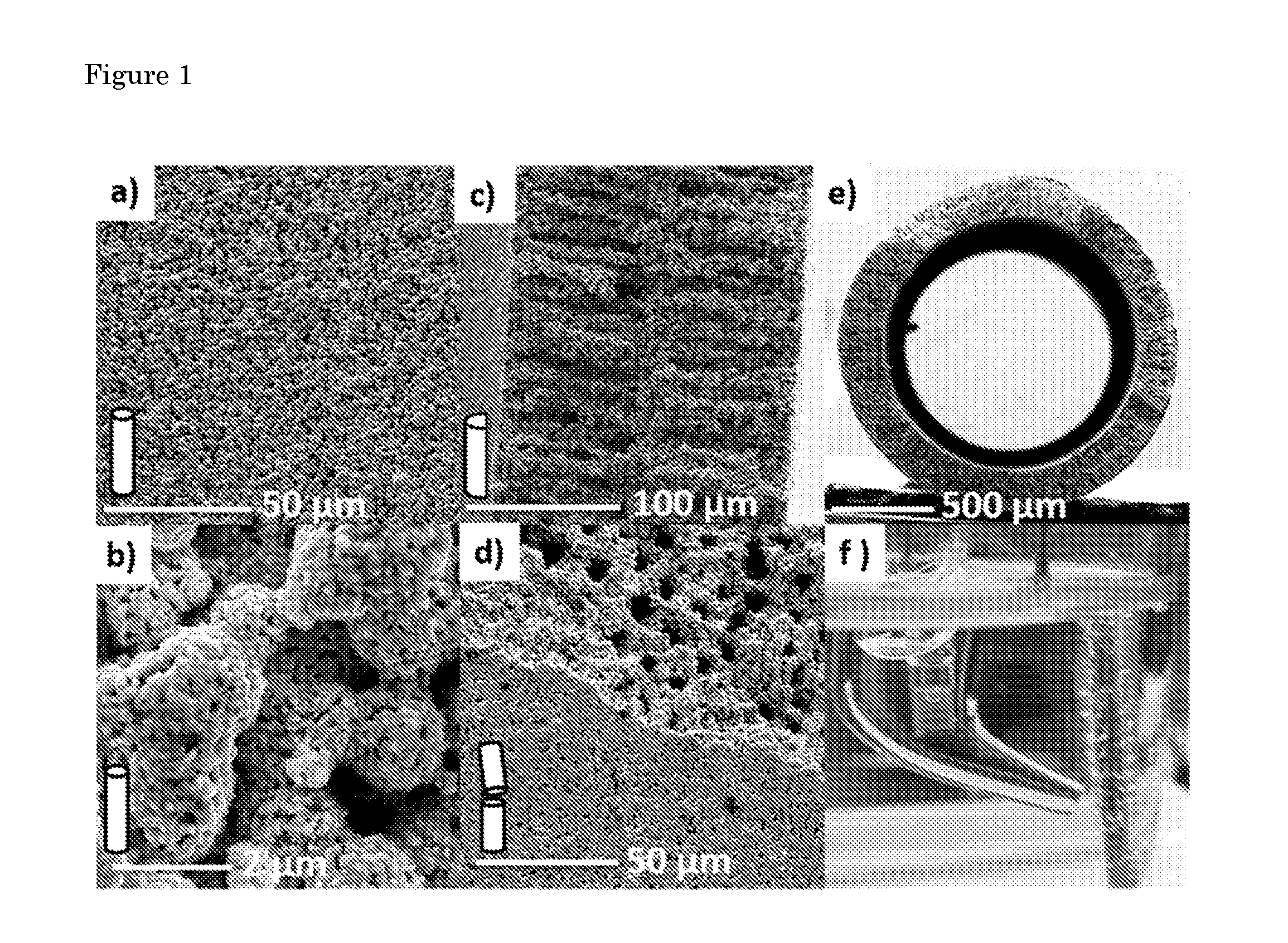
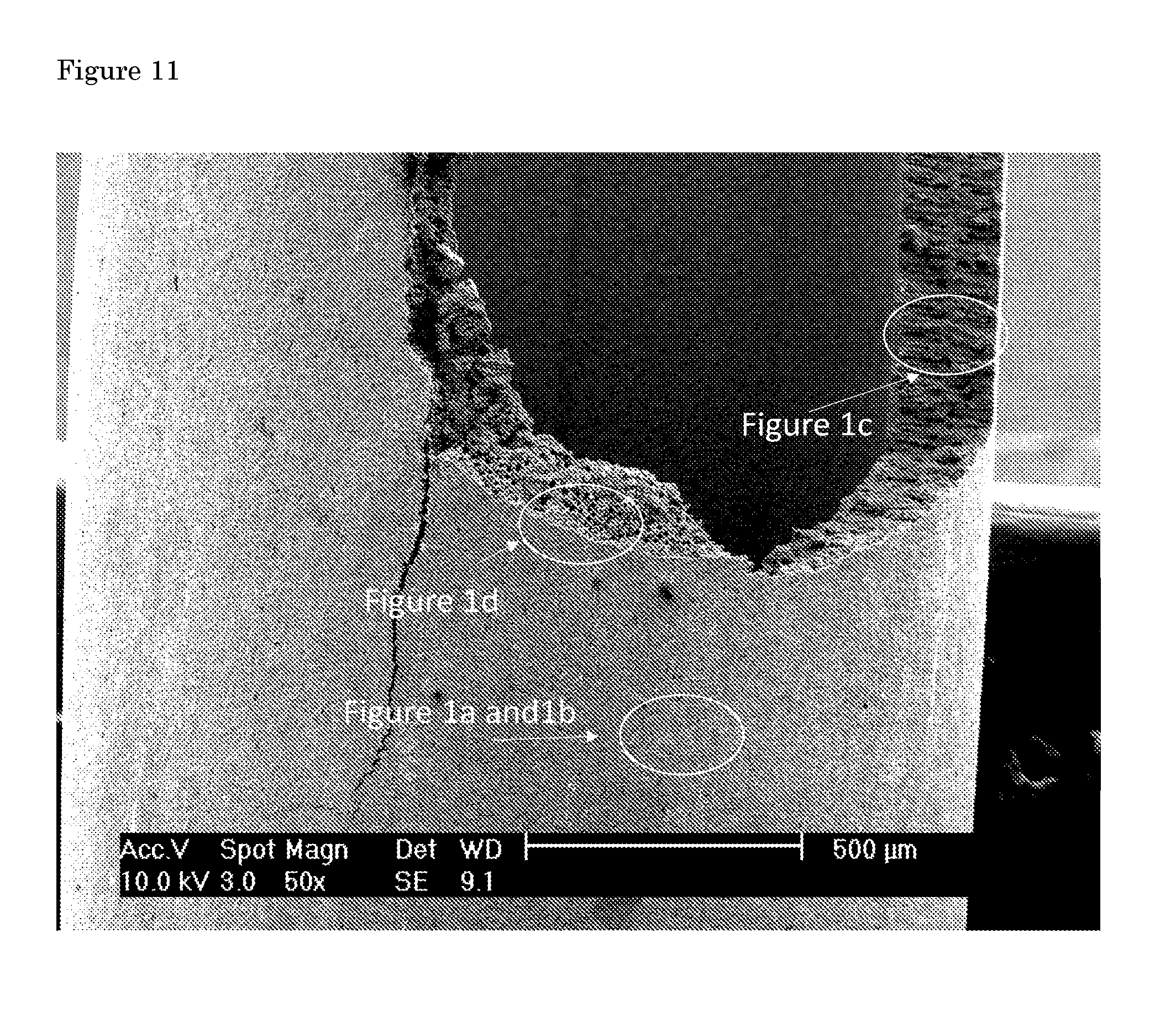
[0016] The preparation of the metal hollow fibers i.e. nickel and stainless steel has been described in the literature previously [Meng et al, J. Alloy Compd. 2009, 470, 461-464; Luiten-Olieman et al, Scripta Mater. 2011, 65, 25-28]. The preparation of Cu hollow fiber, on the other hand, has not been reported to the best of our knowledge. The inventors adapted the method and prepared Cu hollow fibers by spinning a mixture containing copper particles, polymer and solvent. The mixture is suitably pressed through a spinneret into a coagulation bath. In this bath, non-solvent induced phase separation arrests the copper particles in the polymer matrix. By adding a bore-liquid during spinning, a hollow fiber is obtained. After thermal treatment, the polymer is decomposed and the copper particles are sintered together, resulting in hollow, porous copper oxide fibers. Hydrogenation of these precursor fibers at elevated temperatures was applied to obtain metallic copper fibers. Typical scanning electron microscope (SEM) images of the Cu hollow fibers are shown in FIG. 1. The low and higher magnification images of the external surface of the fibers show that the fiber is composed of aggregated copper particles forming an interconnected 3-D porous structure (FIG. 1a and 1b). The cross-sectional images of the deliberately broken fibers exhibit fingerlike voids perpendicular to the surface which are terminated by a 10-15 .mu.m thick sponge-like porous outer layer (FIGS. 1c and 1d). Cu hollow fibers can have outer and inner diameters ranging from 1.55.+-.0.1 mm to 1.3.+-.0.05 mm respectively (FIG. 1e). CO.sub.2 was pushed from the inside out of the fiber, creating an overpressure around 1.70.+-.0.1 bars due to the resistance of the porous structure. Gas bubbles emerging out of the fiber can be clearly seen in FIG. 1f. The pressure is considered to spread out the finger-like holes without resistance and to drop across the porous outer layer to 1.05 bar. When a potential is applied, electrochemical reduction likely takes place both at the interface of CO.sub.2 (g) and water (1) in contact with copper (s), as well as near the electrode surface with dissolved CO.sub.2.
[0017] For monitoring the electrochemical activity of the fibers, linear sweep voltammetry experiments were performed in CO.sub.2 saturated electrolyte, while Ar or CO.sub.2 were purged through the fibers (FIG. 2). The current densities recorded during Ar purge are mostly due to hydrogen evolution, which has an onset potential of around -0.25 V vs. RHE. Bubbling CO.sub.2 through the fiber leads to about two-fold increase in cathodic current densities at potentials between -0.2 and -0.4 V vs. RHE. On the contrary, on both smooth or rough copper surfaces lower current densities are under CO.sub.2 atmosphere as compared to Ar atmosphere. This was attributed to co-adsorption of CO, weakening the binding energy of hydrogen to the electrode surface and retarding the hydrogen evolution reaction. In other words, most of the cathodic current was considered to be a result of hydrogen production at low potentials, even in the presence of CO.sub.2 or CO. So the high cathodic currents achieved in the presence of CO.sub.2 on Cu hollow fiber is already an indication of distinctive activity towards CO.sub.2 reduction.
[0018] To confirm the catalytic activity, the faradaic efficiency of the major products was measured by varying the applied potential between -0.15 V and -0.55 V vs. RHE (FIG. 2b). The onset of CO formation is located at -0.15 V vs. RHE, implying an overpotential of just .about.40 mV above the equilibrium potential (-0.11 V vs. RHE). The total faradaic efficiency of the CO.sub.2 reduction products adds up to .about.85% at potentials between -0.3 V and -0.5 V vs. RHE. Specifically, a peak faradaic efficiency of .about.72% was obtained for CO at a potential of -0.4 V vs. RHE, whereas the maximum faradaic efficiency for CO on polycrystalline copper and copper nanoparticles is around 20% (-0.8 V vs. RHE) and 45% (J.sub.CO.about.300 .mu.A/cm.sup.2), respectively. The decrease in faradaic efficiency of CO at higher potentials (<-0.5 V) implies CO formation is now most likely limited by desorption. Additionally, ethylene was detected at these potentials (see table 1), which is formed by coupling of two CO molecules.
TABLE-US-00001 TABLE 1 Chemical analysis of the precursor copper powder as provided by Skyspring Nanomaterials Copper Powder Purity 99% Average Particle Size 1-2 .mu.m Contents C 5000 O 10000 Al 1000 Ni 500 Fe 500 Pb <100 Cd <100 Hg <10
[0019] On that account, the formation of hydrocarbons still requires relatively large overpotentials on Cu hollow fiber, and direct CO.sub.2 reduction to energy dense products remains a challenge. Formation of CO at very low potentials implies a better stabilization of the key CO.sub.2-- intermediate which is formed by the first electron transfer to adsorbed CO.sub.2. The remarkable activity of the rough copper electrodes prepared by oxidation of copper and subsequent reduction, namely oxide-derived copper, can be attributed to the metastable sites exist in grain boundaries. However, reasonable activities also achieved towards formic acid and CO with faradaic efficiency up to 45% at a potential of -0.5 V vs. RHE on copper nanofoams prepared by electrodeposition. Interestingly, the production of formic acid was controlled by changing thickness of the electrodeposited layer similar to the oxide-derived copper where CO.sub.2 reduction activity was a function of the parent oxide layer thickness. In addition, Reske et al. showed the reduction of CO.sub.2 can be significantly enhanced by decreasing the size of the copper nanoparticles which is correlated to the number of uncoordinated cites [Reske et al., J. Am. Chem. Soc. 2014, 136, 6978-69861]. By considering all these studies, the increase in the CO.sub.2 reduction activity on porous, foamy and nanoparticulate copper structures might be associated with the abundance of the low coordinated sites such as kinks, steps etc. which influence the binding energy of the key intermediate CO.sub.2--.
[0020] On the other hand, contrary to polycrystalline copper and copper nanoparticles, formation of formic acid is relatively suppressed. Mechanistic information can be deduced for the two electron reduction of CO.sub.2 to CO by using a Tafel plot shown in FIG. 2c. The first step involves an electron transfer to adsorbed CO.sub.2 which is coupled to a proton transfer. In following steps, COOH intermediate accepts an electron and proton to form CO and water. A slope around 116 mVdec.sup.-1 was recorded for copper different electrodes that suggests a mechanism in which initial electron transfer to CO.sub.2 is rate determining. The lower slope of 93 mVdec.sup.-1 associated with the lower potential region is most likely due to non-uniform potential or current distribution within the solid porous matrix of the hollow fiber. This might be either caused by the ohmic drop within solid porous matrix or inhomogeneous distribution of the reactants to the electrode surface. More importantly, at higher potentials, an apparent change in Tafel slope is observed, which suggests a change in rate determining step or mechanism. By also considering the fact that higher pressures can induce CO production on copper nanoparticles and indium electrodes, the rate of CO production compared to formic acid might be more sensitive to CO.sub.2 concentration as has been suggested for CO.sub.2 reduction in media of low proton availability. Likewise, studies on various metal electrodes in water showed a higher order dependence on CO.sub.2 pressure in a second Tafel region for CO. Still, CO production as a function of CO.sub.2 concentration in the solution requires further investigation.
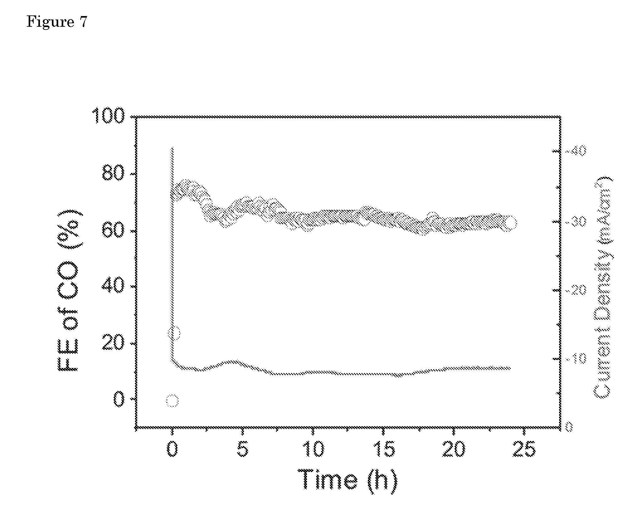
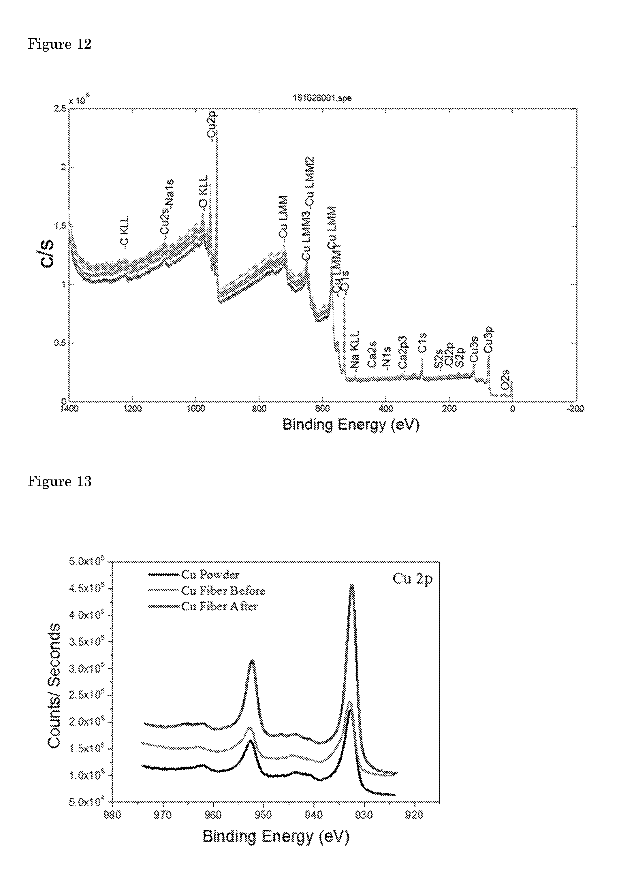
[0021] To test the stability of the Cu hollow fibers, 24 hours of continuous electrolysis was performed at an applied potential of -0.4 V vs. RHE (FIG. 2d and FIG. 7). After a.about.10% drop in activity in the first 7 hours, noticeable from the slight curvature of the plot in FIG. 2d, stable performance was achieved in the next 17 hours of experiment. SEM images of the electrode after electrolysis showed no apparent difference in the morphology of the Cu hollow fiber (FIG. 8). The activity of polycrystalline Cu is well known to degrade very quickly within an hour, unless very high purity electrolytes and electrodes are employed. Cu nanoparticles on the other hand exhibited quite stable performance when thick oxide layers are used as copper precursor. However, it is important to note that these studies usually employ ultra-high purity copper plates (99.9999%) whereas the purity of the precursor copper powders used in this study is relatively low (99%), significantly reducing the price for commercial application. X-ray photoelectron spectroscopy (XPS) analysis of the precursor copper powder and Cu hollow fibers before the and after electrolysis experiments indicated that there is no detectable amount (>% 0.1) of transition metal impurity at the surface of the catalyst (FIG. 12). The major impurity within the hollow fiber is carbon which is also present in the precursor copper powder. XPS spectra of the fibers indicated the surface is composed of mainly with Cu.sup.0 and Cu.sub.2O, the latter associated with the exposure of the sample to air (FIG. 13). More importantly, the absence of shift in binding energy of Cu2p peaks before and after preparation and electrolysis suggests the absence of any alloy or carbide formation upon annealing or electrolysis.
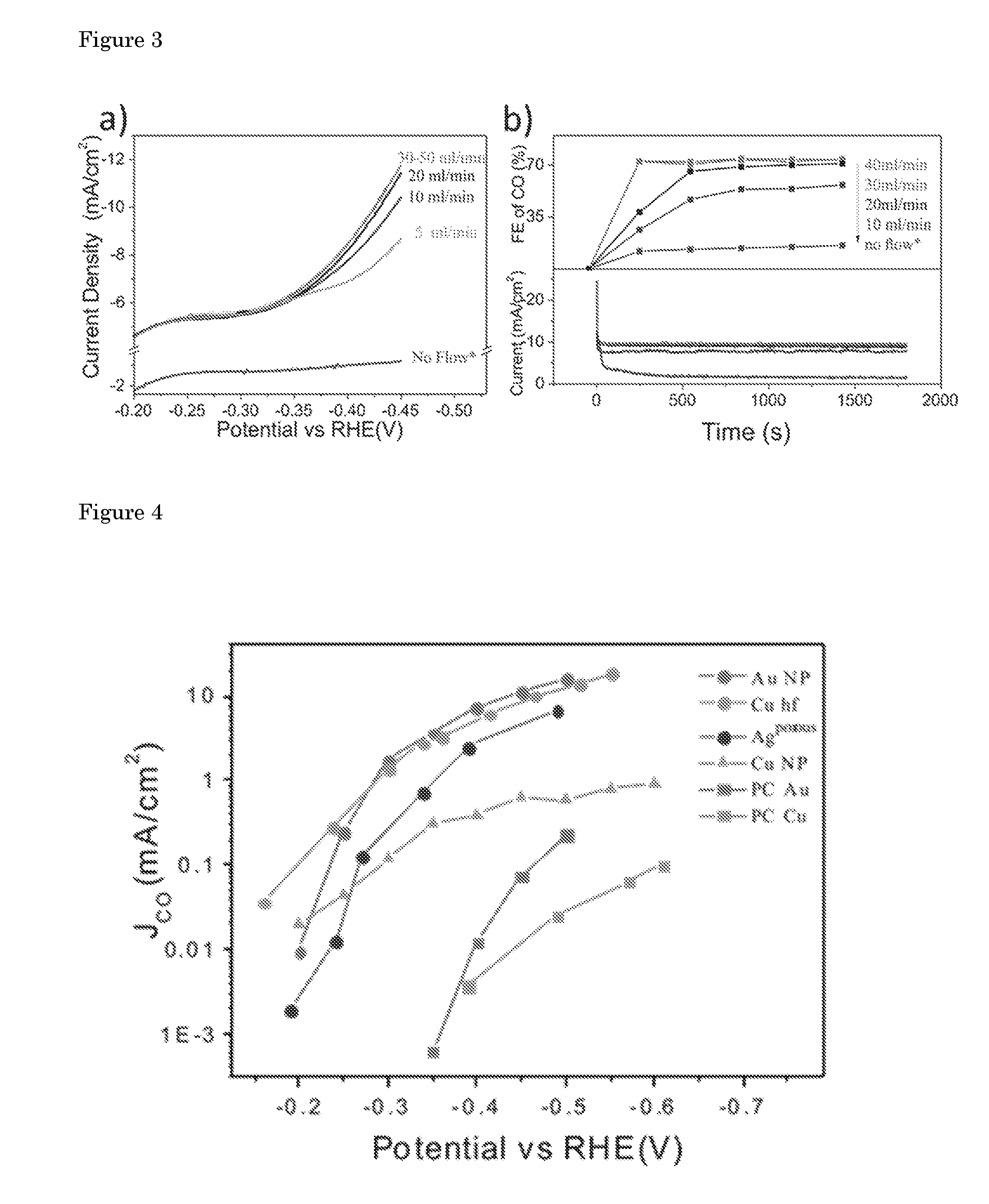
[0022] FIGS. 3a and 3b show the effect of the CO.sub.2 flow rate on overall current density and faradaic efficiency of CO at an applied voltage of -0.4 V vs. RHE, respectively. The current density undoubtedly is proportional to the CO.sub.2 flow rate above -0.35 V vs. RHE, until a certain flow rate was reached. The change in faradaic efficiency of CO is consistent with the increase in current density. A maximum faradaic efficiency of 75% was recorded for CO at a potential of -0.4 V vs. RHE at optimized flow rate which is almost twice of what has been recently reported for copper nanoparticles at the same potential. The experiments as a function of flow rate indicate that the faradaic efficiency of CO strictly depends on supply of CO.sub.2 to the electrode surface. Therefore, the high faradaic efficiencies observed in this study is a result of improved mass transfer of CO.sub.2 integrated with the defect rich, active and porous copper electrode. The steady behavior above the flow rate of 30 ml min.sup.-1 implies all the active sites are involved in converting CO.sub.2 to CO, and the catalyst has reached its intrinsic limit. Previously, the CO.sub.2 reduction rate in aqueous conditions was shown to be proportional to the CO.sub.2 pressure on different metal electrodes, suggesting high degrees of coverage were not achieved even at pressures as high as 25 atm. On the other hand, the intermediate CO, was considered to have a high degree of coverage during electrochemical CO.sub.2 reduction on copper electrodes, supported by spectroscopic studies. By considering these facts, the high current densities achieved on Cu hollow fibers is attributed to better removal of CO from the surface, induced by a very high local concentration of CO.sub.2 near the electrode. Besides an improved performance, this also enables the evaluation of the intrinsic activity of the electrocatalyst especially when a competing reaction, i.e. hydrogen evolution, simultaneously takes place.
[0023] An overview of the performance of different catalysts' as compared to our Cu hollow fiber (Cu hf) is shown in FIG. 4. The partial current density of CO (J.sub.CO), representing the formation rate of CO, is plotted against the applied potential. Besides the fact that the faradaic efficiency towards CO is significantly improved compared to polycrystalline Cu and Cu nanoparticles, the partial current density for CO formation on Cu hollow fiber is exceptionally high. Cu hollow fibers can reduce CO.sub.2 to CO electrochemically at a potential of -0.4 V vs. RHE, with over 15 to 400 times higher rate than polycrystalline Cu and Cu nanoparticles, respectively at a potential of -0.4 V vs. RHE. While outcompeting the currently best performing copper based electrodes, Cu hollow fibers also show comparable activities at low potentials (-0.2 V to -0.6 V vs. RHE) to that of noble metal catalysts evaluated in aqueous solutions (Au nanoparticles, nanoporous Ag). It should be recalled that noble metal electrodes benefit from a high overpotential for hydrogen evolution, while Cu hollow fibers perform so well on the basis of the improved mass transfer of CO.sub.2.
[0024] In addition to the comparison in FIG. 4, a beneficial comparison would be on the basis of the performance of gas diffusion electrodes, where the reaction also takes place at gas-liquid-solid interfaces. Unfortunately, most of the studies use high overpotentials (>1 V) to evaluate hydrocarbon formation on Cu gas diffusion electrodes. In general, much higher currents densities (0.1-1 A/cm.sup.2) are reported on gas diffusion electrodes which can be attributed to high applied potentials which decreases the overall energy efficiency. For instance, no CO formation was reported on Ag gas diffusion electrodes at low potentials where recorded onset potential was around -0.6 V vs. RHE. Nevertheless, the inventors believe using a defect rich, rough and porous copper based catalyst on a conventional gas diffusion electrode would also yield a remarkable performance. The thickness of the porous catalyst layer used in gas diffusion electrodes is typically in the range from 5-20 .mu.m, similarly for copper hollow fibers, the electrode thickness that participates into the electrolysis is around 15-20 .mu.m estimated from nickel electrodeposition and subsequent energy dispersive X-ray analysis (FIG. 10). This thickness is also comparable to oxide films used to prepare rough electrodes or electrodeposited 3-D porous structures employed as electrodes. The geometrical current density of the fibers are calculated by normalizing the current to the outer surface area of the cylindrical hollow fibers. In addition, it is a common practice to use the projected area of the 3-D electrode, or so called apparent area, in conventional gas diffusion electrodes to report current densities.
[0025] Gas diffusion electrodes played an important role in fundamental electrocatalysis, however their mass production delayed due to economic and technical issues. The mature dry-wet spinning process allows mass production of organic hollow fibers that are already commercially available. Preparation of hollow metal fibers with diameters in the range of 100-500 .mu.m, on the other hand, was developed recently which adapts a very similar method, implying a great potential of large scale production. Microtubular geometry has been deployed and investigated in solid oxide fuel cells for decades which could allow the adaptation of technologies developed such as stack design, sealing, current collection etc. Metal hollow fibers might provide cost effective and compact diffusion media and/or catalyst layer for gas diffusion electrodes which might also eliminate resistance associated with catalyst support interface. Furthermore, we believe there is plenty of room to increase the production rate by considering the controllability of the internal and external structure of the hollow fibers. The thickness of the active catalyst layer can be tuned by changing 3-D geometry, support material, porosity and/or precursor particle size, to further optimize the production rate.
[0026] The results reported herein highlight a new area to explore for the development of robust electrodes that can efficiently catalyze conversion of CO.sub.2 at high rates in aqueous media. Employing a simple, compact Cu hollow fiber as both gas diffuser and an electrode, leads to very high CO production rates which are comparable to what has been achieved by using noble metals. Selective formation of CO is observed with a maximum faradaic efficiency of 75% when high flow rates are used. The porous nature of the hollow fibers provides high surface area and correspondingly high geometric current densities for CO.sub.2 reduction ranging from 2 mA cm.sup.-2 to 17 mA cm.sup.-2 at moderate potentials (-0.3 to -0.5 V vs. RHE). The remarkable performance of the hollow fibers are attributed to defect-rich porous structure in addition to the excellent mass transport capabilities. In general, hollow fibers provide new possibilities to design practically relevant microtubular electrodes and electrochemical reactors where one or more reactants are present in the gas phase.
[0027] In a further aspect, the invention is directed to a method of electrolyzing carbon dioxide in an aqueous electrochemical cell comprising an anode and a cathode, wherein the cathode comprises one or more metal hollow fiber electrodes according to the invention, said method comprising [0028] applying a potential between said anode and cathode, and [0029] purging CO.sub.2 or a gas mixture comprising CO.sub.2 through the wall of the metal hollow fiber electrode.
[0030] Preferably, the method of the invention is performed in an aqueous environment.
[0031] The method can suitably be performed at a temperature in the range of 5-80.degree. C., such as in the range of 10-30.degree. C., more preferably in the range of 15-25.degree. C.
[0032] In a further aspect, the invention is directed to a method of converting carbon dioxide into one or more selected from the group consisting of carbon monoxide, formic acid, a formate, methanol, acetaldehyde, methane, ethylene and ethane, comprising electrolyzing CO.sub.2 by a method according to the invention of electrolyzing carbon dioxide in an aqueous electrochemical cell comprising an anode and a cathode as described herein.
[0033] In a preferred embodiment, the carbon dioxide is converted into carbon monoxide.
[0034] In yet a further aspect, the invention is directed to a method of preparing a metal hollow fiber electrode according to the invention, comprising: [0035] spinning a mixture comprising copper particles, polymer and solvent together with a bore liquid to obtain hollow fibers; [0036] subjecting the hollow fibers to a thermal treatment such that copper particles are sintered together, thereby yielding hollow copper oxide fibers; [0037] hydrogenating the hollow copper oxide fibers.
[0038] The thermal treatment in this method preferably comprises subjecting the hollow fibers to a temperature in the range of 500-800.degree. C., such as in the range of 550-700.degree. C. This thermal treatment is preferably performed for a period of 1-6 hours, such as a period of 2-5 hours.
[0039] The hydrogenation preferably comprises subjecting the hollow copper oxide fibers to a temperature in the range of 200-400.degree. C., such as in the range of 250-350.degree. C. This hydrogenation is preferably performed for a period of 30-120 minutes, such as 45-90 minutes. Preferably the hydrogenation comprises subjecting the hollow copper oxide fibers to a flow of hydrogen in the concentration range of 0.1-100 vol. %, such as 5 vol. % in a balance gas.
[0040] In yet a further aspect, the invention is directed to the use of a metal hollow fiber electrode according to the invention as cathode and/or gas diffuser.
Preparation of Cu Hollow Fibers
[0041] Commercial available copper powder (Skyspring nanomaterials, 99%) with particle size of 1-2 .mu.m was used as catalyst precursor. N-methylpyrrolidone (NMP, 99.5 wt. %, Sigma Aldrich), Polyetherimide (PEI, Ultem 1000, General Electric) were used as solvent and polymer respectively. Copper powder (71.09 wt. %) was added to the NMP (22.14 wt. %) followed by stirring and ultrasonic treatment for 30 min. After addition of PEI (6.76 wt. %) this mixture was heated and kept at 50.degree. C. and 60.degree. C. for 30 minutes and 2 hours, respectively. Next, the solution is allowed to cool down by stirring overnight which is followed by degassing. Vacuum was applied for 90 min and the mixture was left overnight.
[0042] Spinning was carried out at room temperature (21.+-.3.degree. C.) using a stainless steel vessel, that was pressurized to 1 bar using nitrogen. The mixture was pressed through a spinneret (inner and outer diameters of 0.8 mm and 2.0 mm, respectively) into a coagulation bath containing tap water. Deionized water was pumped through the bore of the spinneret with a speed of 30 ml min.sup.-1 and the air gap was set to 1 cm.
[0043] After spinning the fibers were kept in the coagulation bath for 1 day to remove traces of NMP, followed by drying for 1 day. The green copper hollow fibers were thermally treated at 600.degree. C. for 3 hours (heating rate and cooling rates: 1.degree. C. min.sup.-1) in air to remove the PEI and subsequent sintering of the copper particles. The oxidized hollow fibers were reduced by hydrogenation at 280.degree. C. for 1 hour (H.sub.2 in Argon: 4%, heating rate and cooling rate: 100.degree. C./min). X-ray diffraction patterns were collected by using a Bruker D2 Phaser x-ray diffractometer, equipped with a Cu-K.alpha. radiation source and operated at 30 kV and 10 mA (FIG. 5). SEM images were taken using a Phillips FEI XL30 FEG-ESEM or FEI Sirion HR-SEM. X-ray photoelectron spectroscopy (XPS) spectrum was collected by using Quantera SXM (Scanning XPS microprobe) spectrometer equipped with Al K.alpha. (1486.6 eV) X-ray source. The source was operated with a 25 W emission power, beam size of 200 .mu.m and pass energy of 224 eV. The resolution of the spectrometer was 0.1 eV and 0.2 eV for high resolution element scan and survey spectra, respectively.
Electrochemical CO.sub.2 Reduction
[0044] All solutions were prepared and all glassware were cleaned by using deionized water (Millipore MilliQ, 18.2 MQ). Electrochemical CO.sub.2 reduction activity of Cu HF's was measured by using three electrode assembly in a glass cell at room temperature and pressures. A Princeton Applied Research versaSTAT 3 potentiostat was used to control the potentials. The counter electrode, Pt mesh, was separated by using a Nafion 112 membrane (Sigma Aldrich). An Ag/AgCl (3 M NaCl BAST) reference electrode was placed near the working electrode by using a Luggin capillary and all the potentials were converted to RHE scale afterwards. IR drops were measured before the electrolysis and compensated manually after the experiments. 4.+-.0.5 cm long Cu HF are used as both working electrode and as gas diffuser. The fibers were sealed from the bottom by using epoxy glue and connected to gas inlet of the cell. The cathodic compartment is filled with 100 ml, 0.3 M KHCO.sub.3 (99.95%, Sigma Aldrich) and purged with CO.sub.2 at least 20 minutes before the experiments. During the electrolysis the CO.sub.2 is purged continuously through the fiber with 20 ml min.sup.-1 unless otherwise indicated, and sampled via gas chromatogram (GC) each 6 minutes. CO, CO.sub.2, H.sub.2 and hydrocarbons are separated with GC equipped with two different columns (ShinCarbon 2 m micropacked column and Rtx-1). A thermal conductivity detector (TCD) and flame ionization detector (FID) were used to perform the quantitative analysis of the gas phase products. The time needed to reach steady state concentration was approximately 10 minutes so all the reaction times were kept at least 20 minutes. A control experiment was conducted at -0.5 V vs. RHE under Argon atmosphere. No CO was detected that might associated with the organic residues remaining from polymers that is used during preparation of the hollow fibers. Liquid products formed during the electrolysis were analyzed by using High Performance Liquid Chromatography (HPLC) (Prominence HPLC, Shimadzu; Aminex HPX 87-H column, Biorad).
Characterization of the Cu hollow fibers
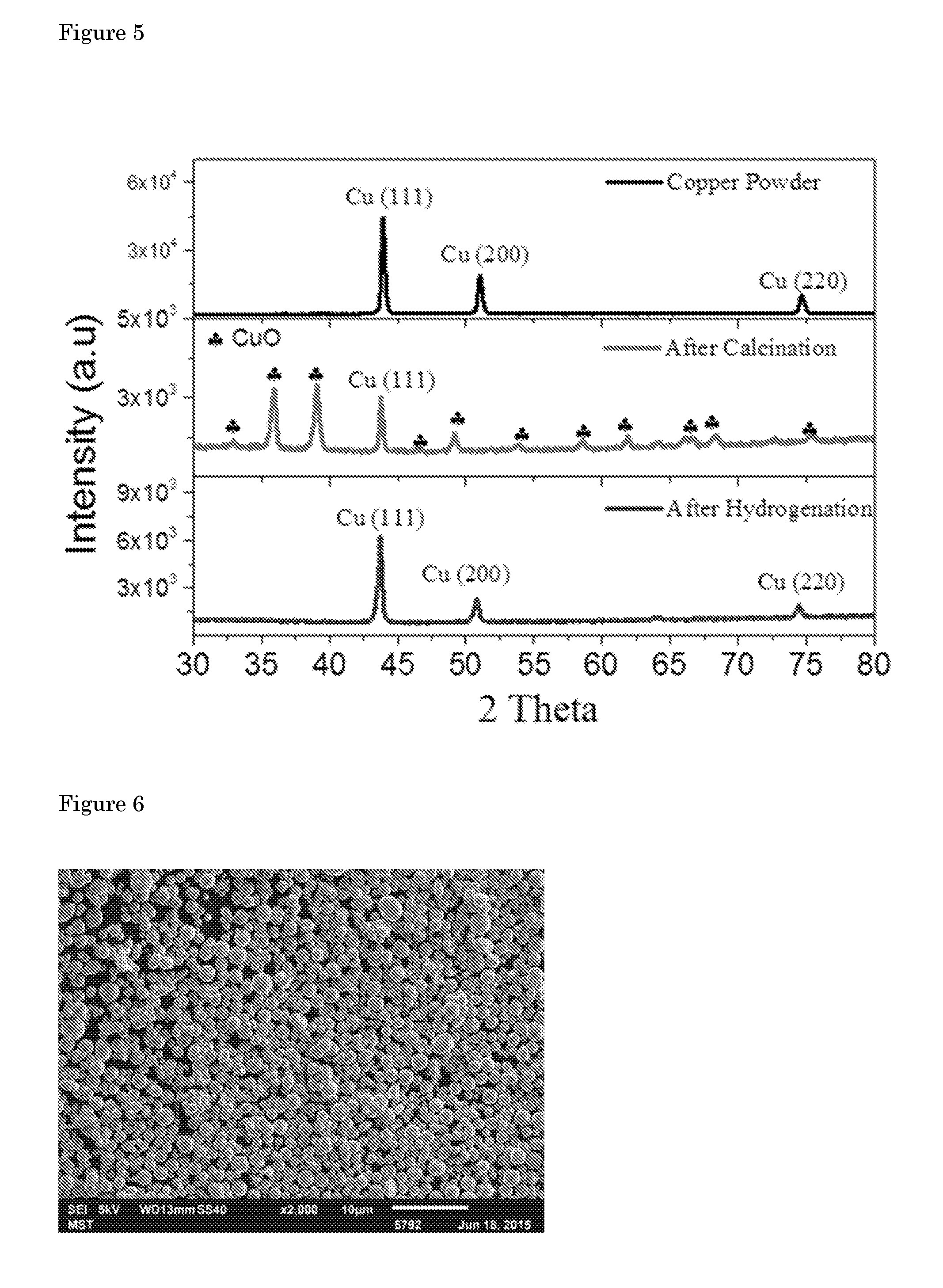
[0045] Certified chemical analysis of the precursor copper powder is given in table 1 (taken from the datasheet provided by the company which supplied the copper powder, Skyspring Nanomaterials). The XRD pattern and SEM images of the copper powder are given in FIGS. 5 and 6. Copper powder is composed of spherical particles with a broad size distribution from 500 nm-2 .mu.m. The XRD pattern after calcination shows that CuO was formed after sintering of the copper particles. The hydrogenation procedure reduces the copper oxide to the metallic form. These fibers were used as both cathode and gas diffuser, purging CO.sub.2 through the side walls of the fiber. A summary of product distribution and total current density as a function of applied potential is provided in table 2. The SEM image of the fibers after 24 hours of electrolysis (FIG. 7) showed changes in the morphology of the fibers are negligible (FIG. 8).
TABLE-US-00002 TABLE 2 Summary of the faradaic efficiencies (FE) as a function of applied potential. Faradaic Efficiency (%) E vs RHE J.sub.total Formic (v) (mA/cm.sup.2) CO Acid Ethylene H.sub.2 Total -0.16 0.24 14.8 0.0 0.0 -- 14.8* -0.24 0.66 42.2 0.0 0.0 -- 42.2* -0.30 2.5 55.9 25.1 0.0 19.4 100.4 -0.34 4.2 65.2 20.1 0.0 12.1 97.4 -0.36 4.8 68.6 16.2 0.0 11.8 96.6 -0.41 8.4 72.4 9.8 0.0 13.9 96.1 -0.47 14.7 68.5 16.5 0.1 11.7 96.8 -0.52 21.3 65.4 18.5 0.15 13.6 97.7 -0.55 35.7 53.3 26.2 0.2 16.9 96.6 *Hydrogen concentrations were not measurable at these low potentials due to the relatively low detection limit of the applied Thermal Conductivity Detector The remaining current is considered to be due to H.sub.2, since no formic acid is detected in this potentials.
[0046] An example for the reproducibility of the experiments is given in FIG. 9. Four different experiments were performed at an applied potential of -0.4 V vs. RHE by using four different Cu hollow fibers. There are only slight variations in faradaic efficiency of CO and geometrical current density when different fibers are employed as electrodes.
[0047] Electrodeposition experiments were performed on Cu hollow fibers to determine the reactive zones. Nickel deposition was performed from solutions of nickel nitrate (50 mM Ni(NO.sub.3).sub.2, 5 mA cm.sup.-2 for 900 s) while purging Ar at 20 ml min.sup.-1. The SEM images in FIG. 10 show that the nickel deposition takes place mostly on the outer surface. Energy dispersive X-ray analysis (EDX) showed that the penetration depth of Nickel through the fiber is around 15-20 .mu.m which indicates the thickness of the electrode utilized during the CO.sub.2 reduction. The noisy character of the line scan is due to porous nature of the Cu hollow fiber. The current values obtained are normalized by the external geometrical surface area of the cylindrical Cu hollow fibers. This has been done by considering the facts that when nanoparticles, rough electrodes or 3-D porous structures are employed as electrodes, the current density is calculated by using the geometrical area of the electrode. The thickness of the electrode utilized during CO.sub.2 reduction in this study is comparable to 3-D porous and nanostructured surfaces. Additionally, for gas diffusion electrodes, it is common to use the projected area of the 3-D electrode. The electrochemical active surface area is important to interpret the catalytic activity of the fibers, whereas the geometrical current density is important for the practical applications. X-ray photoelectron spectroscopy (XPS) was collected by using Quantera SXM (Scanning XPS microprobe) spectrometer equipped with Al K.alpha. (1486.6 eV) X-ray source. The source was operated with a 25 W emission power, beam size of 200 .mu.m and pass energy of 224 eV. The resolution of the spectrometer was 0.1 eV and 0.2 eV for high resolution element scan and survey spectra, respectively. High resolution elemental scans are performed for Cu, C, O, Al, Ni, Fe, Pb, Cd, Hg. The minimal detectable amount changes with the sensitivity factors for the elements. As a rule of thumb: lighter elements have smaller sensitivity factors and are less good detectable than heavy elements. Exceptions to this rule of thumb are Al, SI, P, S, Cl, As, Se and Br. For our survey scans, light elements 0.5% and heavy elements<0.1%. On flat samples, like the pieces of copper foil, it is normal that hydrocarbons from ambient air stick to almost all surface. The layer can rapidly grow to more than 0.5 nm and will show up as a big part in the calculated contents. The layer also acts as a shield for all electrons coming from below. Sputtering a flat surface for a short time with an argon ion beam can reduce the amount of carbon dramatically. However this sputtering at the same time destroys the chemistry at the surface. On the powder the carbon concentration is often lower because there is too much surface for all the hydrocarbons to stick too. The atomic concentrations of the elements measured can be calculated and with the formula
C x = I x / S x I i / S i ##EQU00001##
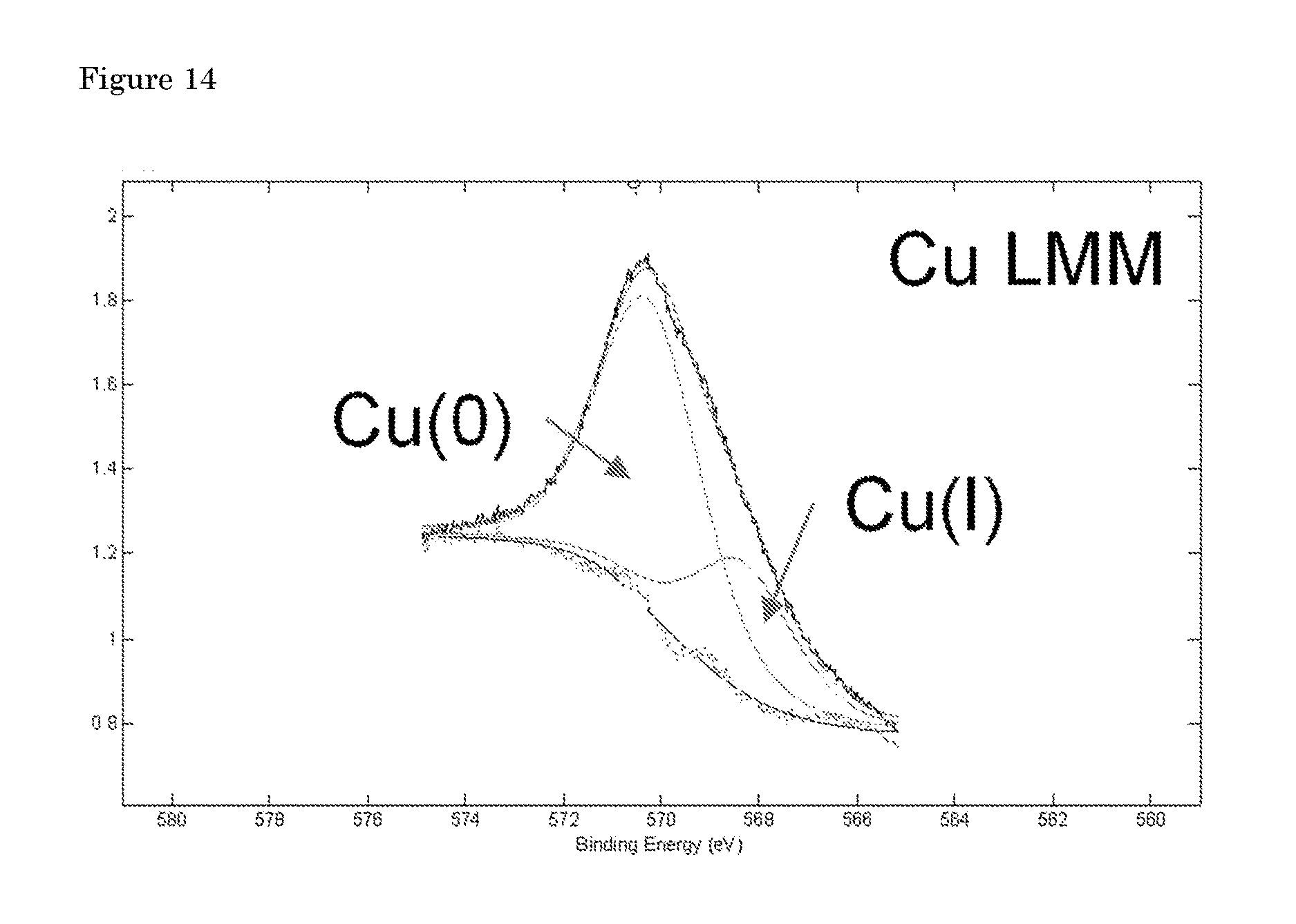
wherein I.sub.i is the peak area of a photoelectron peak and S.sub.i is the relative sensitivity factor of the peak. The calculated amounts for the detected elements are given in table 3. The elemental scan Cu 2p XPS spectrum indicated the presence of Cu.sup.0 and/or Cu.sup.1+, but the peaks associated with Cu.sup.2+ in all the spectra were absent. Cu.sup.0 and Cu.sup.1+ ratio can be roughly estimated by using Cu LMM peaks (FIG. 14). There are minor impurities at the surface of the Cu hollow fiber before electrolysis which are most like associated with the polymers used in spinning process. These impurities are removed upon electrolysis.
TABLE-US-00003 TABLE 3 The atomic concentrations of the elements calculated from the intensities of the peaks present in XPS spectra Cu.sup.0/ C.sup.+ From Cu LMM Sample C N O Na S Cl Ca Cu fit Cu 9.39 -- 43.87 -- -- -- -- 46.74 21/79 Powder Cu 28.82 0.65 44.76 1.15 1.30 0.28 0.37 22.67 52/48 Fiber (before) Cu 7.53 -- 42.40 -- -- -- -- 50.06 73/27 Fiber (after)
BRIEF DESCRIPTION OF THE FIGURES
[0048] FIG. 1: Physical characterization of Cu hollow fibers. a) Low and b) High magnification SEM images of the outer surface of the Cu hollow fiber. c) Cross-sectional image of perpendicularly broken Cu hollow fiber. d) Outer surface of parallel broken Cu hollow fiber along with the cross-section. e) Image of Cu hollow fiber taken by the electron microscope, and f) Cu hollow fiber employed as an electrode (20 ml min.sup.-1 gas flow and no applied potential.
[0049] FIG. 2: Electrocatalytic performance of Cu hollow fibers. a) Linear polarization curves for Cu hollow fiber under CO.sub.2 and Ar atmosphere in 0.3 M of KHCO.sub.3 (Scan rate 50 mV s.sup.-1). b) Faradaic efficiency (FE) of CO, formic acid and H.sub.2 at different potentials. c) Overpotential vs. partial current density of CO for Cu hollow fiber. d) Total production of CO at an applied potential of -0.4 V for 24 hours of continuous experiment (flow rate of CO.sub.2: 20 ml min.sup.-1).
[0050] FIG. 3: Electrocatalytic performance as a function of flow rate. a) Linear polarization curves for different flow rates of CO.sub.2 (Scan rate 50 mV s.sup.-1). b) Faradaic efficiency (FE) of CO for different flow rates of CO.sub.2 and corresponding current densities (applied potential of -0.4 V vs. RHE, 0.3 M KHCO.sub.3. * Experiments are performed in CO.sub.2 saturated solutions.
[0051] FIG. 4: Activity of various electrodes in water: Overview of different catalysts' performance at different potentials with a plot of partial current density of CO at different potentials.
[0052] FIG. 5: XRD patterns of the starting copper powder, Cu hollow fiber after calcination at 600.degree. C., and the copper fiber after hydrogenation.
[0053] FIG. 6: SEM image of "as received" copper powder.
[0054] FIG. 7: The faradaic efficiency (FE) of CO and total current density at an applied potential of -0.4 V for 24 hours of continuous experiment (flow rate of CO.sub.2: 20 ml min.sup.-1).
[0055] FIG. 8: SEM images of the Cu hollow fibers after 24 hours of electrolysis.
[0056] FIG. 9: Reproducibility tests with 4 different fibers at a potential of -0.4 V vs. RHE. Flow rate of CO.sub.2: 20 ml min.sup.-1.
[0057] FIG. 10: EDX analysis demonstrating the wt. % of electrodeposited nickel as a function of location from the outer surface. Deposition of Ni was achieved on the copper hollow fibers feeding 20 ml min.sup.-1 of argon through the porous wall into the Ni.sup.2+ solution.
[0058] FIG. 11: SEM image of Cu hollow fiber showing the locations of the SEM images taken to construct FIG. 1.
[0059] FIG. 12: X-ray photoelectron spectroscopy survey for copper hollow fibers before electrolysis (includes 5 repeated scans).
[0060] FIG. 13: High-resolution X-ray photoelectron spectra demonstrating the Cu 2p peaks indicative of predominantly Cu.sup.0.
[0061] FIG. 14: High-resolution X-ray photoelectron spectrum of the Cu LMM region for Cu hollow fibers after electrolysis. Some Cu(I) might be present in the material.
* * * * *
D00001
D00002
D00003
D00004
D00005
D00006
D00007
D00008
D00009
D00010
XML
uspto.report is an independent third-party trademark research tool that is not affiliated, endorsed, or sponsored by the United States Patent and Trademark Office (USPTO) or any other governmental organization. The information provided by uspto.report is based on publicly available data at the time of writing and is intended for informational purposes only.
While we strive to provide accurate and up-to-date information, we do not guarantee the accuracy, completeness, reliability, or suitability of the information displayed on this site. The use of this site is at your own risk. Any reliance you place on such information is therefore strictly at your own risk.
All official trademark data, including owner information, should be verified by visiting the official USPTO website at www.uspto.gov. This site is not intended to replace professional legal advice and should not be used as a substitute for consulting with a legal professional who is knowledgeable about trademark law.