Steel Sheet And Method For Producing The Same
Kohsaka; Noriaki ; et al.
U.S. patent application number 16/320209 was filed with the patent office on 2019-09-05 for steel sheet and method for producing the same. This patent application is currently assigned to JFE Steel Corporation. The applicant listed for this patent is JFE Steel Corporation. Invention is credited to Noriaki Kohsaka, Tatsuya Nakagaito.
| Application Number | 20190271052 16/320209 |
| Document ID | / |
| Family ID | 61162311 |
| Filed Date | 2019-09-05 |
| United States Patent Application | 20190271052 |
| Kind Code | A1 |
| Kohsaka; Noriaki ; et al. | September 5, 2019 |
STEEL SHEET AND METHOD FOR PRODUCING THE SAME
Abstract
Provided are a steel sheet which has a tensile strength of 900 MPa or higher and excellent weldability, and a method for producing the steel sheet. The steel sheet has a specific composition and a microstructure containing, in terms of area fraction, ferrite of 30% or less (including 0%), tempered martensite of 70% or more (including 100%), and the balance other than ferrite and the tempered martensite of 10% or less (including 0%) in total, the tempered martensite having an average grain size thereof is 5 .mu.m or lower, the tempered martensite having iron-based carbides, which have average particle sizes of 100 nm or less, precipitated on grain boundaries, and the tempered martensite containing, in terms of atomic concentration, 5 atom % or more in total of Si and Mn on the grain boundaries of the tempered martensite. The steel sheet has a tensile strength of 900 MPa or higher.
| Inventors: | Kohsaka; Noriaki; (Chiyoda-ku, Tokyo, JP) ; Nakagaito; Tatsuya; (Chiyoda-ku, Tokyo, JP) | ||||||||||
| Applicant: |
|
||||||||||
|---|---|---|---|---|---|---|---|---|---|---|---|
| Assignee: | JFE Steel Corporation Tokyo JP |
||||||||||
| Family ID: | 61162311 | ||||||||||
| Appl. No.: | 16/320209 | ||||||||||
| Filed: | August 10, 2017 | ||||||||||
| PCT Filed: | August 10, 2017 | ||||||||||
| PCT NO: | PCT/JP2017/029035 | ||||||||||
| 371 Date: | January 24, 2019 |
| Current U.S. Class: | 1/1 |
| Current CPC Class: | C22C 38/58 20130101; C22C 38/005 20130101; C22C 38/36 20130101; C21D 6/004 20130101; C21D 8/0426 20130101; C21D 8/0226 20130101; C21D 8/0463 20130101; B23K 11/11 20130101; C21D 8/0236 20130101; C22C 18/00 20130101; C21D 2211/008 20130101; C22C 38/002 20130101; C22C 38/22 20130101; C22C 38/06 20130101; C21D 2211/004 20130101; C22C 38/28 20130101; C22C 38/44 20130101; C22C 38/38 20130101; B23K 2103/04 20180801; C23C 2/28 20130101; C21D 9/46 20130101; C22C 38/02 20130101; B23K 11/16 20130101; C21D 6/008 20130101; C22C 38/54 20130101; C21D 6/005 20130101; C22C 38/46 20130101; C21D 8/0205 20130101; C23C 2/06 20130101; C21D 6/002 20130101; C21D 8/0405 20130101; C21D 8/0263 20130101; C21D 8/0436 20130101; C22C 38/001 20130101; C22C 38/04 20130101; C22C 38/34 20130101; C22C 38/14 20130101; C22C 38/60 20130101; C22C 38/08 20130101; C23C 2/40 20130101; C21D 2211/005 20130101; C22C 38/48 20130101; C22C 38/12 20130101; C23C 2/02 20130101; C21D 6/001 20130101; C21D 6/02 20130101; C22C 38/008 20130101; C22C 38/50 20130101; B23K 31/12 20130101 |
| International Class: | C21D 8/04 20060101 C21D008/04; C22C 38/06 20060101 C22C038/06; C22C 38/02 20060101 C22C038/02; C22C 38/04 20060101 C22C038/04; C22C 38/00 20060101 C22C038/00; C22C 38/12 20060101 C22C038/12; C22C 38/14 20060101 C22C038/14; C22C 38/08 20060101 C22C038/08; C22C 38/34 20060101 C22C038/34; C22C 38/36 20060101 C22C038/36; C22C 38/60 20060101 C22C038/60; C22C 38/54 20060101 C22C038/54; C22C 38/44 20060101 C22C038/44; C22C 38/48 20060101 C22C038/48; C22C 38/50 20060101 C22C038/50; C22C 38/46 20060101 C22C038/46; C22C 38/22 20060101 C22C038/22; C22C 38/58 20060101 C22C038/58; C21D 9/46 20060101 C21D009/46; C23C 2/06 20060101 C23C002/06; C23C 2/02 20060101 C23C002/02; C23C 2/40 20060101 C23C002/40 |
Foreign Application Data
| Date | Code | Application Number |
|---|---|---|
| Aug 10, 2016 | JP | 2016-157761 |
Claims
1.-9. (canceled)
10. A steel sheet comprising: a composition containing, in mass %, C: 0.07% or more and 0.20% or less, Si: 0.60% or more and 1.65% or less, Mn: 1.8% or more and 3.5% or less, P: 0.05% or less, S: 0.005% or less, Al: 0.08% or less, N: 0.0060% or less, and the balance being Fe and unavoidable impurities; a microstructure containing, by area fraction, ferrite of 30% or less (including 0%), tempered martensite of 70% or more (including 100%), and the balance other than the ferrite and the tempered martensite including 10% or less (including 0%) in total, the tempered martensite having an average grain size of is 5 .mu.m or less, the tempered martensite having iron-based carbides, which have an average particle size of 100 nm or less, precipitated on grain boundaries thereof, and the tempered martensite containing, in terms of atomic concentration, 5% or more in total of Si and Mn on the grain boundaries of the tempered martensite; and a tensile strength of 900 MPa or higher.
11. The steel sheet according to claim 10, wherein the composition further contains, in mass %, one or two or more selected from at least one of groups A to C: group A V: 0.001% or more and 1% or less, Ti: 0.001% or more and 0.3% or less, and Nb: 0.001% or more and 0.3% or less, and the microstructure contains a carbide containing at least one of V, Ti, and Nb and having an average particle size of 20 nm or less. group B Cr: 0.001% or more and 1.0% or less, Mo: 0.001% or more and 1.0% or less, Ni: 0.001% or more and 1.0% or less, B: 0.0001% or more and 0.0050% or less, and Sb: 0.001% or more and 0.050% or less, and the microstructure contains, in terms of atomic concentration, 5% or more in total of Cr, Mo, Ni, B, and Sb on the grain boundaries of the tempered martensite. Group C REM, Sn, Mg, and Ca of 0.0001% or more and 0.1% or less in total.
12. The steel sheet according to claim 10, further comprising a coating layer on the surface thereof.
13. The steel sheet according to claim 11, further comprising a coating layer on the surface thereof.
14. The steel sheet according to claim 12, wherein the coating layer has a composition containing, in mass %, Fe: 20.0% or less, Al: 0.001% or more and 3.5% or less, one or two or more selected from Pb, Sb, Si, Sn, Mg, Mn, Ni, Cr, Co, Ca, Cu, Li, Ti, Be, Bi, and REM of 0% to 3.5% in total, and the balance being Zn and unavoidable impurities.
15. The steel sheet according to claim 13, wherein the coating layer has a composition containing, in mass %, Fe: 20.0% or less, Al: 0.001% or more and 3.5% or less, one or two or more selected from Pb, Sb, Si, Sn, Mg, Mn, Ni, Cr, Co, Ca, Cu, Li, Ti, Be, Bi, and REM of 0% to 3.5% in total, and the balance being Zn and unavoidable impurities.
16. The steel sheet according to claim 12, wherein the coating layer is an alloyed hot-dip layer.
17. The steel sheet according to claim 13, wherein the coating layer is an alloyed hot-dip layer.
18. The steel sheet according to claim 14, wherein the coating layer is an alloyed hot-dip layer.
19. The steel sheet according to claim 15, wherein the coating layer is an alloyed hot-dip layer.
20. A method for producing the steel sheet according to claim 10, the method comprising: heating a steel material at 1150.degree. C. or higher and 1350.degree. C. or lower, hot-rolling including rough rolling and finish rolling the steel material at a finish rolling temperature of 820.degree. C. or higher, coiling at 350.degree. C. or higher and 680.degree. C. or lower, cold-rolling, heating and retaining at 840.degree. C. or higher for 30 seconds or more, then cooling to 100.degree. C. or lower at an average cooling rate of 200.degree. C./s or more from a cooling starting temperature to a Ms point, re-heating and retaining at 840.degree. C. or higher for 30 seconds or more, then cooling to (Ms point--100.degree. C.) or lower at an average cooling rate of 20.degree. C./s or more from a cooling starting temperature to (Ms point--100.degree. C.), heating or cooling as necessary, and retaining at 200.degree. C. or higher and 400.degree. C. or lower for 20 seconds or more and 1800 seconds or less.
21. A method for producing the steel sheet according to claim 11, the method comprising: heating a steel material at 1150.degree. C. or higher and 1350.degree. C. or lower, hot-rolling including rough rolling and finish rolling the steel material at a finish rolling temperature of 820.degree. C. or higher, coiling at 350.degree. C. or higher and 680.degree. C. or lower, cold-rolling, heating and retaining at 840.degree. C. or higher for 30 seconds or more, then cooling to 100.degree. C. or lower at an average cooling rate of 200.degree. C./s or more from a cooling starting temperature to a Ms point, re-heating and retaining at 840.degree. C. or higher for 30 seconds or more, then cooling to (Ms point--100.degree. C.) or lower at an average cooling rate of 20.degree. C./s or more from a cooling starting temperature to (Ms point--100.degree. C.), heating or cooling as necessary, and retaining at 200.degree. C. or higher and 400.degree. C. or lower for 20 seconds or more and 1800 seconds or less.
22. A method for producing the steel sheet according to claim 12, the method comprising: heating a steel material at 1150.degree. C. or higher and 1350.degree. C. or lower, hot-rolling including rough rolling and finish rolling at a finish rolling temperature of 820.degree. C. or higher, coiling at 350.degree. C. or higher and 680.degree. C. or lower, cold-rolling, heating and retaining at 840.degree. C. or higher for 30 seconds or more, then cooling to 100.degree. C. or lower at an average cooling rate of 200.degree. C./s or more from a cooling starting temperature to 200.degree. C., re-heating and retaining at 840.degree. C. or higher for 10 seconds or more and 150 seconds or less, then cooling to 260.degree. C. or lower at an average cooling rate of 20.degree. C./s or more from a cooling starting temperature to 260.degree. C., heating or cooling as necessary, retaining at 200.degree. C. or higher and 400.degree. C. or lower for 20 seconds or more and 150 seconds or less, and subjecting to a coating treatment by immersing in a plating bath, or subjecting to an alloying treatment in addition to the coating treatment.
23. A method for producing the steel sheet according to claim 13, the method comprising: heating a steel material at 1150.degree. C. or higher and 1350.degree. C. or lower, hot-rolling including rough rolling and finish rolling at a finish rolling temperature of 820.degree. C. or higher, coiling at 350.degree. C. or higher and 680.degree. C. or lower, cold-rolling, heating and retaining at 840.degree. C. or higher for 30 seconds or more, then cooling to 100.degree. C. or lower at an average cooling rate of 200.degree. C./s or more from a cooling starting temperature to 200.degree. C., re-heating and retaining at 840.degree. C. or higher for 10 seconds or more and 150 seconds or less, then cooling to 260.degree. C. or lower at an average cooling rate of 20.degree. C./s or more from a cooling starting temperature to 260.degree. C., heating or cooling as necessary, retaining at 200.degree. C. or higher and 400.degree. C. or lower for 20 seconds or more and 150 seconds or less, and subjecting to a coating treatment by immersing in a plating bath, or subjecting to an alloying treatment in addition to the coating treatment.
24. A method for producing the steel sheet according to claim 14, the method comprising: heating a steel material at 1150.degree. C. or higher and 1350.degree. C. or lower, hot-rolling including rough rolling and finish rolling at a finish rolling temperature of 820.degree. C. or higher, coiling at 350.degree. C. or higher and 680.degree. C. or lower, cold-rolling, heating and retaining at 840.degree. C. or higher for 30 seconds or more, then cooling to 100.degree. C. or lower at an average cooling rate of 200.degree. C./s or more from a cooling starting temperature to 200.degree. C., re-heating and retaining at 840.degree. C. or higher for 10 seconds or more and 150 seconds or less, then cooling to 260.degree. C. or lower at an average cooling rate of 20.degree. C./s or more from a cooling starting temperature to 260.degree. C., heating or cooling as necessary, retaining at 200.degree. C. or higher and 400.degree. C. or lower for 20 seconds or more and 150 seconds or less, and subjecting to a coating treatment by immersing in a plating bath, or subjecting to an alloying treatment in addition to the coating treatment.
25. A method for producing the steel sheet according to claim 15, the method comprising: heating a steel material at 1150.degree. C. or higher and 1350.degree. C. or lower, hot-rolling including rough rolling and finish rolling at a finish rolling temperature of 820.degree. C. or higher, coiling at 350.degree. C. or higher and 680.degree. C. or lower, cold-rolling, heating and retaining at 840.degree. C. or higher for 30 seconds or more, then cooling to 100.degree. C. or lower at an average cooling rate of 200.degree. C./s or more from a cooling starting temperature to 200.degree. C., re-heating and retaining at 840.degree. C. or higher for 10 seconds or more and 150 seconds or less, then cooling to 260.degree. C. or lower at an average cooling rate of 20.degree. C./s or more from a cooling starting temperature to 260.degree. C., heating or cooling as necessary, retaining at 200.degree. C. or higher and 400.degree. C. or lower for 20 seconds or more and 150 seconds or less, and subjecting to a coating treatment by immersing in a plating bath, or subjecting to an alloying treatment in addition to the coating treatment.
26. A method for producing the steel sheet according to claim 16, the method comprising: heating a steel material at 1150.degree. C. or higher and 1350.degree. C. or lower, hot-rolling including rough rolling and finish rolling at a finish rolling temperature of 820.degree. C. or higher, coiling at 350.degree. C. or higher and 680.degree. C. or lower, cold-rolling, heating and retaining at 840.degree. C. or higher for 30 seconds or more, then cooling to 100.degree. C. or lower at an average cooling rate of 200.degree. C./s or more from a cooling starting temperature to 200.degree. C., re-heating and retaining at 840.degree. C. or higher for 10 seconds or more and 150 seconds or less, then cooling to 260.degree. C. or lower at an average cooling rate of 20.degree. C./s or more from a cooling starting temperature to 260.degree. C., heating or cooling as necessary, retaining at 200.degree. C. or higher and 400.degree. C. or lower for 20 seconds or more and 150 seconds or less, and subjecting to a coating treatment by immersing in a plating bath, or subjecting to an alloying treatment in addition to the coating treatment.
27. A method for producing the steel sheet according to claim 17, the method comprising: heating a steel material at 1150.degree. C. or higher and 1350.degree. C. or lower, hot-rolling including rough rolling and finish rolling at a finish rolling temperature of 820.degree. C. or higher, coiling at 350.degree. C. or higher and 680.degree. C. or lower, cold-rolling, heating and retaining at 840.degree. C. or higher for 30 seconds or more, then cooling to 100.degree. C. or lower at an average cooling rate of 200.degree. C./s or more from a cooling starting temperature to 200.degree. C., re-heating and retaining at 840.degree. C. or higher for 10 seconds or more and 150 seconds or less, then cooling to 260.degree. C. or lower at an average cooling rate of 20.degree. C./s or more from a cooling starting temperature to 260.degree. C., heating or cooling as necessary, retaining at 200.degree. C. or higher and 400.degree. C. or lower for 20 seconds or more and 150 seconds or less, and subjecting to a coating treatment by immersing in a plating bath, or subjecting to an alloying treatment in addition to the coating treatment.
28. A method for producing the steel sheet according to claim 18, the method comprising: heating a steel material at 1150.degree. C. or higher and 1350.degree. C. or lower, hot-rolling including rough rolling and finish rolling at a finish rolling temperature of 820.degree. C. or higher, coiling at 350.degree. C. or higher and 680.degree. C. or lower, cold-rolling, heating and retaining at 840.degree. C. or higher for 30 seconds or more, then cooling to 100.degree. C. or lower at an average cooling rate of 200.degree. C./s or more from a cooling starting temperature to 200.degree. C., re-heating and retaining at 840.degree. C. or higher for 10 seconds or more and 150 seconds or less, then cooling to 260.degree. C. or lower at an average cooling rate of 20.degree. C./s or more from a cooling starting temperature to 260.degree. C., heating or cooling as necessary, retaining at 200.degree. C. or higher and 400.degree. C. or lower for 20 seconds or more and 150 seconds or less, and subjecting to a coating treatment by immersing in a plating bath, or subjecting to an alloying treatment in addition to the coating treatment.
29. A method for producing the steel sheet according to claim 19, the method comprising: heating a steel material at 1150.degree. C. or higher and 1350.degree. C. or lower, hot-rolling including rough rolling and finish rolling at a finish rolling temperature of 820.degree. C. or higher, coiling at 350.degree. C. or higher and 680.degree. C. or lower, cold-rolling, heating and retaining at 840.degree. C. or higher for 30 seconds or more, then cooling to 100.degree. C. or lower at an average cooling rate of 200.degree. C./s or more from a cooling starting temperature to 200.degree. C., re-heating and retaining at 840.degree. C. or higher for 10 seconds or more and 150 seconds or less, then cooling to 260.degree. C. or lower at an average cooling rate of 20.degree. C./s or more from a cooling starting temperature to 260.degree. C., heating or cooling as necessary, retaining at 200.degree. C. or higher and 400.degree. C. or lower for 20 seconds or more and 150 seconds or less, and subjecting to a coating treatment by immersing in a plating bath, or subjecting to an alloying treatment in addition to the coating treatment.
Description
CROSS REFERENCE TO RELATED APPLICATIONS
[0001] This is the U.S. National Phase application of PCT/JP2017/029035, filed Aug. 10, 2017, which claims priority to Japanese Patent Application No. 2016-157761, filed Aug. 10, 2016, the disclosures of these applications being incorporated herein by reference in their entireties for all purposes.
FIELD OF THE INVENTION
[0002] The present invention relates to a steel sheet and a method for producing the steel sheet.
BACKGROUND OF THE INVENTION
[0003] In recent years, from the viewpoint of global environment conservation, the whole automobile industry aims to improve fuel efficiency of the automobile to regulate CO.sub.2 emissions. To improve the fuel efficiency of the automobile, reducing the weight of the automobile by using the components thereof with the thinner walls is most effective. Therefore, in recent years, the use of high-strength steel sheet (highly strengthened steel sheet) as a material for the automobile parts has increased.
[0004] Meanwhile, the weldability of the steel sheet tends to deteriorate as the strength increases. Therefore, a steel sheet having not only the high strength, but also excellent weldability is desired. A steel sheet that does not have the satisfactory weldability cannot be used for the automobile parts or the like, because such a steel sheet causes defects such as cracks when joining automotive members to each other by welding. For reducing the weights of the automobile parts or the like, it is essential to develop a steel sheet that has both high strength and weldability, and various techniques have been proposed so far to provide high-strength cold-rolled steel sheets and hot dipped steel sheets that are focused on the weldability.
[0005] For example, according to PTL 1, a high-strength hot-dip galvanized steel sheet with excellent spot weldability, anti-crash property and bending formability can be obtained by containing, in mass %, C: 0.05 to 0.15%, Si: 0.01 to 1.00%, Mn: 1.5 to 4.0%, P: 0.100% or less, S: 0.02% or less, Al: 0.01 to 0.50%, Cr: 0.010 to 2.000%, Nb: 0.005 to 0.100%, Ti: 0.005 to 0.100%, B: 0.0005 to 0.0050%, while containing Si, Mn, Cr, and B in a specific range, and having a microstructure (steel structure) containing, in terms of area fraction, ferrite: 10% or less, bainitic ferrite: 2 to 30%, and martensite: 60 to 98%, where the proportion of retained austenite determined by using an X-ray diffraction method is less than 2%, the proportion of massive martensite adjacent only to bainite in the whole microstructure is 10% or less, and a difference in hardness is specified between positions that are located 100 .mu.m and 20 .mu.m away from the surface.
[0006] According to PTL 2, a cold-rolled steel sheet with excellent spot weldability and with a tensile strength of 980 MPa or higher can be obtained by containing, in mass %, C: 0.05 to 0.13%, Si: 0.05 to 2.0%, Mn: 1.5 to 4.0%, P: 0.05% or less, S: 0.005% or less, Al: 0.01 to 0.1%, Cr: 0.05 to 1.0%, Nb: 0.010 to 0.070%, Ti: 0.005 to 0.040%, and N: 0.0005 to 0.0065%, wherein 70% or more of Ti contained in the steel is precipitated, and 15% or more of Nb in the steel is in a solute state.
[0007] According to PTL 3, a cold-rolled steel sheet, a hot-dip galvanized steel sheet, and a hot-dipped galvannealed steel sheet with excellent ductility, stretch flange formability, and weldability, having a tensile strength of 980 MPa or higher and 0.2% proof stress of 700 MPa or less can be obtained, while these contain, in mass %, C: 0.07 to 0.15%, Si: 1.1 to 1.6%, Mn: 2.0 to 2.8%, P: more than 0% and 0.015% or less, S: more than 0% and 0.005% or less, Al: 0.015 to 0.06%, Ti: 0.010 to 0.03%, and B: 0.0010 to 0.004%, and have a microstructure to be described below having, at a position located at 1/4 of the sheet thickness away from the surface of the steel sheet, an area fraction satisfying tempered martensite: 10 area % or more and less than 30 area %, bainite: more than 70 area %, a total of tempered martensite and bainite: 90 area % or more, ferrite: 0 area % or more and 5 area % or less, and retained austenite: 0 area % or more and 4 area % or less.
PATENT LITERATURE
[0008] PTL 1: Japanese Patent No. 5858199
[0009] PTL 2: Japanese Unexamined Patent Application Publication No. 2015-200013
[0010] PTL 3: Japanese Unexamined Patent Application Publication No. 2016-37650
SUMMARY OF THE INVENTION
[0011] In the technique proposed in PTL 1, only specification of the C, Si, P and S contents is done as the requirements for excellent spot weldability, and the spot weldability is not sufficient in some cases.
[0012] In the technique proposed in PTL 2, it is described that Nb-based precipitates are dissolved by heating at a temperature of (Ts-50.degree.) C. or higher in the slab reheating step before hot rolling, but an annealing temperature of 900.degree. C. or lower is a temperature range where Nb-based carbides inevitably precipitate, thus solute Nb cannot be stably retained at 15%.
[0013] In the technique proposed in PTL 3, while only lowering C is described as the direction for improving weldability, likewise in PTL 1, the spot weldability is not sufficient in some cases.
[0014] Aspects of the present invention have been made in view of such circumstances, and an object thereof is to provide a steel sheet with a tensile strength of 900 MPa or higher and excellent weldability, and a method for producing the steel sheet.
[0015] To solve the problems mentioned above, the present inventors conducted intensive studies on the requirements for a steel sheet with both a tensile strength of 900 MPa or higher and excellent weldability. The sheet thickness of the steel sheet being studied in this case was 0.4 mm or more and 3.2 mm or less. In spot welding, depending on conditions, a cracking problem occurred after welding. As a result of intensive studies on the welding conditions and the microstructures of the steel sheets where cracking occurred, it was found that, when welding a galvanized steel sheet and a cold-rolled steel sheet together or welding galvanized steel sheets to each other, cracks were induced due to grain boundary corrosion by zinc; that, for suppressing the grain boundary corrosion by zinc, it was effective to control concentrations of the elements on the grain boundary by reducing a difference in hardness from the weld metal part; and that cracking was also induced by coarse precipitates existing on the grain boundary. Aspects of the present invention have been completed on the basis of such findings and the summary is as follows.
[1] A steel sheet having a composition containing, in mass %, C: 0.07% or more and 0.20% or less, Si: 0.60% or more and 1.65% or less, Mn: 1.8% or more and 3.5% or less, P: 0.05% or less, S: 0.005% or less, Al: 0.08% or less, N: 0.0060% or less, and the balance being Fe and unavoidable impurities; a microstructure containing, in terms of area fraction, ferrite of 30% or less (including 0%), tempered martensite of 70% or more (including 100%), and the balance other than the ferrite and the tempered martensite including 10% or less (including 0%) in total, the tempered martensite having an average grain size of 5 .mu.m or less, the tempered martensite having iron-based carbides, which have an average particle size of 100 nm or less, precipitated on grain boundaries thereof, and the tempered martensite containing, in terms of atomic concentration, 5% or more in total of Si and Mn on the grain boundaries of the tempered martensite; and a tensile strength of 900 MPa or higher. [2] The steel sheet according to [1], in which the composition further contains, in mass %, one or two or more selected from V: 0.001% or more and 1% or less, Ti: 0.001% or more and 0.3% or less, and Nb: 0.001% or more and 0.3% or less, and the microstructure contains a carbide containing at least one of V, Ti and Nb and having an average particle size of 20 nm or less. [3] The steel sheet according to [1] or [2], in which the composition further contains, in mass %, one or two or more selected from Cr: 0.001% or more and 1.0% or less, Mo: 0.001% or more and 1.0% or less, Ni: 0.001% or more and 1.0% or less, B: 0.0001% or more and 0.0050% or less, and Sb: 0.001% or more and 0.050% or less, and the microstructure contains, in terms of atomic concentration, 5% or more in total of Cr, Mo, Ni, B, and Sb on the grain boundaries of the tempered martensite. [4] The steel sheet according to any of [1] to [3], in which the composition further contains, in mass %, one or two or more selected from REM, Sn, Mg, and Ca of 0.0001% or more and 0.1% or less in total. [5] The steel sheet according to any of [1] to [4], further including a coating layer on a surface thereof. [6] The steel sheet according to [5], in which the coating layer has a composition containing, in mass %, Fe: 20.0% or less, Al: 0.001% or more and 3.5% or less, one or two or more selected from Pb, Sb, Si, Sn, Mg, Mn, Ni, Cr, Co, Ca, Cu, Li, Ti, Be, Bi and REM of 0% to 3.5% in total, and the balance being Zn and unavoidable impurities. [7] The steel sheet according to [5] or [6], in which the coating layer is an alloyed hot-dip layer. [8] A method for producing the steel sheet according to any of [1] to [4], the method including: heating a steel material at 1150.degree. C. or higher and 1350.degree. C. or lower, hot-rolling including rough rolling and finish rolling the steel material at a finish rolling temperature of 820.degree. C. or higher, coiling at 350.degree. C. or higher and 680.degree. C. or lower, cold-rolling, heating and retaining at 840.degree. C. or higher for 30 seconds or more, then cooling to 100.degree. C. or lower at an average cooling rate of 200.degree. C./s or more from a cooling starting temperature to a Ms point, re-heating and retaining at 840.degree. C. or higher for 30 seconds or more, then cooling to (Ms point--100.degree. C.) or lower at an average cooling rate of 20.degree. C./s or more from a cooling starting temperature to (Ms point--100.degree. C.), heating or cooling as necessary, and retaining at 200.degree. C. or higher and 400.degree. C. or lower for 20 seconds or more and 1800 seconds or less. [9] A method for producing the steel sheet according to any of [5] to [7], the method comprising: heating a steel material at 1150.degree. C. or higher and 1350.degree. C. or lower, hot-rolling including rough rolling and finish rolling at a finish rolling temperature of 820.degree. C. or higher, coiling at 350.degree. C. or higher and 680.degree. C. or lower, cold-rolling, heating and retaining at 840.degree. C. or higher for 30 seconds or more, then cooling to 100.degree. C. or lower at an average cooling rate of 200.degree. C./s or more from a cooling starting temperature to 200.degree. C., re-heating and retaining at 840.degree. C. or higher for 10 seconds or more and 150 seconds or less, then cooling to 260.degree. C. or lower at an average cooling rate of 20.degree. C./s or more from a cooling starting temperature to 260.degree. C., heating or cooling as necessary, retaining at 200.degree. C. or higher and 400.degree. C. or lower for 20 seconds or more and 150 seconds or less, and subjecting to a coating treatment by immersing in a plating bath, or subjecting to an alloying treatment in addition to the coating treatment.
[0016] The steel sheet according to aspects of the present invention has both high strength with a tensile strength (TS) of 900 MPa or higher and excellent weldability. When the steel sheet according to aspects of the present invention is applied as automobile parts, further reduction in weight of the automobile parts is realized.
DETAILED DESCRIPTION OF EMBODIMENTS OF THE INVENTION
[0017] Hereinafter, embodiments according to the present invention will be described. In addition, the present invention is not limited to the embodiments described below.
[0018] <Composition>
[0019] A steel sheet according to aspects of the present invention has a composition containing, in mass %, C: 0.07% or more and 0.20% or less, Si: 0.60% or more and 1.65% or less, Mn: 1.8% or more and 3.5% or less, P: 0.05% or less, S: 0.005% or less, Al: 0.08% or less, N: 0.0060% or less, and the balance being Fe and unavoidable impurities.
[0020] The composition may further contain, in mass %, one or two or more selected from V: 0.001% or more and 1% or less, Ti: 0.001% or more and 0.3% or less, and Nb: 0.001% or more and 0.3% or less.
[0021] In addition, the composition may further contain, in mass %, one or two or more selected from Cr: 0.001% or more and 1.0% or less, Mo: 0.001% or more and 1.0% or less, Ni: 0.001% or more and 1.0% or less, B: 0.0001% or more and 0.0050% or less, and Sb: 0.001% or more and 0.050% or less.
[0022] Hereinafter, each of the components will be specifically described. In the following description, representing the content of components refers to "mass %".
[0023] C: 0.07% or More and 0.20% or Less
[0024] Carbon (C) is an element related to the hardness of tempered martensite and effective for increasing the strength of the steel sheet. In order to obtain a tensile strength of 900 MPa or higher, at least the C content needs to be 0.07% or more. Meanwhile, when C content exceeds 0.20%, the hardness of the weld metal in spot welding excessively increases, spot weldability is lowered due to occurrence of difference in hardness from the heat-affected zone (HAZ). Furthermore, the spot weldability deteriorates also in view of increased particle size of the iron-based carbide precipitated on the grain boundary of the tempered martensite. Therefore, C content is in a range between 0.07% or more and 0.20% or less. Preferably, the lower limit of the C content is 0.09% or more. More preferably, it is 0.10% or more, or still more preferably, 0.11% or more. Preferably, the upper limit of the C content is 0.19% or less. More preferably, it is 0.18% or less, or still more preferably, 0.16% or less.
[0025] Si: 0.60% or More and 1.65% or Less
[0026] Silicon (Si) is an element having an effect of preventing the occurrence of cracking by lowering the wettability of the grain boundary by its presence on the grain boundary, and preventing grain boundary corrosion by zinc during spot welding. In order to obtain this effect, it is necessary that Si content is at least 0.60%. Meanwhile, when the Si content exceeds 1.65%, adverse effects on chemical convertibility and plating property are noticeable, thereby application to an automotive member being difficult. Therefore, Si content is in a range between 0.60% or more and 1.65% or less. Preferably, the lower limit of the Si content is 0.70% or more. More preferably, the lower limit of the Si content is 0.80% or more, or still more preferably, 0.90% or more. Preferably, the upper limit of the Si content is 1.60% or less. More preferably, the upper limit of the Si content is 1.55% or less, or still more preferably, 1.50% or less.
[0027] Mn: 1.8% or More and 3.5% or Less
[0028] As with Si, manganese (Mn) is an element having an effect of preventing grain boundary corrosion in spot welding by its presence on the grain boundary of the tempered martensite. In order to obtain this effect, it is necessary that the Mn content is 1.8% or more. Meanwhile, when the Mn content exceeds 3.5%, the chemical convertibility and the plating property deteriorate. Therefore, the Mn content is 1.8% or more and 3.5% or less. Preferably, the lower limit of the Mn content is 1.9% or more. More preferably, the lower limit of the Mn content is 2.1% or more, or still more preferably, 2.3% or more. Preferably, the upper limit of the Mn content is 3.2% or less. More preferably, the upper limit of the Mn content is 3.0% or less, or still more preferably, 2.9% or less.
[0029] P: 0.05% or Less
[0030] Phosphorus (P) is an element that induces low temperature embrittlement, and thus, P is an element that causes cracking during cooling at the time of welding. Therefore, from the viewpoint of weldability, it is preferable to reduce the P content as much as possible, and according to aspects of the present invention, up to 0.08% of P content is allowed. Preferably, the P content is 0.03% or less. While it is preferable to reduce the P content as much as possible or P may not be contained at all, 0.002% of P may inevitably be mixed through the process of production.
[0031] S: 0.005% or Less
[0032] Sulfur (S) forms coarse sulfides in steel which are elongated during hot rolling to form wedge-shaped inclusions that adversely affect weldability. Therefore, it is preferable to reduce the S content as much as possible. According to aspects of the present invention, up to 0.005% can be allowed, and accordingly, the upper limit of S content is 0.005%. Preferably, the S content is 0.003% or less. While it is preferable to reduce the S content as much as possible or S may not be contained at all, 0.0002% of S may inevitably be mixed through the process of production.
[0033] Al: 0.08% or Less
[0034] When Aluminum (Al) is added as a deoxidizer at the stage of steelmaking, it is preferable that Al content be 0.02% or more. More preferably, the Al content is 0.03% or more. Meanwhile, Al forms coarse oxide which causes weldability to deteriorate. Therefore, the upper limit of the Al content is 0.08%. Preferably, the Al content is 0.07% or less. More preferably, the Al content is 0.06% or less, or still more preferably, 0.05% or less.
[0035] N: 0.0060% or Less,
[0036] Nitrogen (N) is a detrimental element that degrades cold aging properties to cause unexpected cracking, or causes micro voids at the time of spot welding to degrade weldability. Therefore, although it is desirable to reduce the N content as much as possible, up to 0.0060% can be allowed in accordance with aspects of the present invention. Preferably, the N content is 0.0050% or less. More preferably, the N content is 0.0050% or less, or still more preferably, 0.0040% or less. While it is preferable to reduce the N content as much as possible or N may not be contained at all, 0.0005% of N may inevitably be mixed through the process of production.
[0037] While the basic composition according to aspects of the present invention is described above, the following components (optional components) may be additionally contained.
[0038] One or Two or More Selected from V: 0.001% or More and 1% or Less, Ti: 0.001% or More and 0.3% or Less, and Nb: 0.001% or More and 0.3% or Less
[0039] V, Ti and Nb are elements that combine with C to form fine carbides, thereby contributing to increasing the strength of the steel sheet. Meanwhile, when excessively contained, the elements precipitate into coarse carbides, resulting in deterioration of weldability. In view of the above, V: 0.001% or more and 1% or less, Ti: 0.001% or more and 0.3% or less, and Nb: 0.001% or more and 0.3% or less. Preferably, the lower limit of the V content is 0.005% or more. More preferably, the lower limit of the V content is 0.050% or more, or still more preferably, 0.100% or more. Preferably, the upper limit of the V content is 0.6% or less. More preferably, the upper limit of the V content is 0.5% or less, or still more preferably, 0.4% or less. Preferably, the lower limit of the Ti content is 0.005% or more. More preferably, the lower limit of the Ti content is 0.010% or more, or still more preferably, 0.020% or more. Preferably, the upper limit of the Ti content is 0.2% or less. More preferably, the upper limit of the Ti content is 0.15% or less, or still more preferably, 0.12% or less. Preferably, the lower limit of the Nb content is 0.005% or more. More preferably, the lower limit of the Nb content is 0.010% or more, or still more preferably, 0.020% or more. Preferably, the upper limit of the Nb content is 0.15% or less. More preferably, the upper limit of the Nb content is 0.12% or less, or still more preferably, 0.08% or less.
[0040] One or two or more selected from Cr: 0.001% or more and 1.0% or less, Mo: 0.001% or more and 1.0% or less, Ni: 0.001% or more and 1.0% or less, B: 0.0001% or more and 0.0050% or less, and Sb: 0.001% or more and 0.050% or less
[0041] Cr, Mo and Ni are elements which have an effect of contributing to increasing the strength of the steel sheet and increasing the atomic concentration on the grain boundary of the tempered martensite to improve spot weldability. Meanwhile, when these elements are excessively added, the transformation point greatly changes. Therefore, a desired steel structure cannot be obtained, and the chemical convertibility and the plating property deteriorate. B and Sb are elements that are present on the grain boundary and increase the surface energy required for crack generation, thereby effectively preventing crack generation in spot welding. When B or Sb is added excessively, the effect is saturated, leading to waste of added elements. In view of the above, Cr: 0.001% or more and 1.0% or less, Mo: 0.001% or more and 1.0% or less, Ni: 0.001% or more and 1.0% or less, B: 0.0001% or more and 0.0050% or less, Sb: 0.001% or more and 0.050% or less. Preferably, the lower limit of the Cr content is 0.010% or more. More preferably, the lower limit of the Cr content is 0.050% or more, or still more preferably, 0.100% or more. Preferably, the upper limit of the Cr content is 0.8% or less. More preferably, the upper limit of the Cr content is 0.7% or less, or still more preferably, 0.6% or less. Preferably, the lower limit of the Mo content is 0.010% or more. More preferably, the lower limit of the Mo content is 0.050% or more, or still more preferably, 0.100% or more. Preferably, the upper limit of the Mo content is 0.6% or less. More preferably, the upper limit of the Mo content is 0.5% or less, or still more preferably, 0.4% or less. Preferably, the lower limit of the Ni content is 0.010% or more. More preferably, the lower limit of the Ni content is 0.020% or more, or still more preferably, 0.030% or more. Preferably, the upper limit of the Ni content is 0.5% or less. More preferably, the upper limit of the Ni content is 0.4% or less, or still more preferably, 0.3% or less. Preferably, the lower limit of the B content is 0.0003% or more. More preferably, the lower limit of the B content is 0.0007% or more, or still more preferably, 0.0010% or more. Preferably, the upper limit of the B content is 0.0030% or less. More preferably, the upper limit of the B content is 0.0025% or less, or still more preferably, 0.0020% or less. Preferably, the lower limit of the Sb content is 0.005% or more. More preferably, the lower limit of the Sb content is 0.008% or more, or still more preferably, 0.010% or more. Preferably, the upper limit of the Sb content is 0.040% or less. More preferably, the upper limit of the Sb content is 0.030% or less, or still more preferably, 0.020% or less.
[0042] One or Two or More Selected from REM, Sn, Mg, and Ca: 0.0001% or More and 0.1% or Less in Total
[0043] REM, Sn, Mg and Ca are elements that improve spot weldability by spheroidizing inclusions. Meanwhile, when these elements are added excessively, the effect is saturated, leading to waste of added elements. In view of the above, one or two or more selected from REM, Sn, Mg, and Ca is 0.0001% or more and 0.1% or less in total. Preferably, the lower limit of one or two or more selected from REM, Sn, Mg, and Ca in total is 0.0005% or more. More preferably, it is 0.0010% or more, or still more preferably, 0.0020% or more. Preferably, the upper limit of one or two or more selected from REM, Sn, Mg, and Ca in total is 0.05% or less. More preferably, it is 0.03% or less, or still more preferably, 0.02% or less.
[0044] The balance other than the components mentioned above is Fe and unavoidable impurities. In addition, when the optional component described above is contained in an amount less than the lower limit, the optional element is regarded as being contained as an unavoidable impurity.
[0045] <Steel Structure>
[0046] Next, the steel structure of a steel sheet according to aspects of the present invention will be described. The steel structure of a steel sheet according to aspects of the present invention contains, in terms of area fraction, ferrite of 30% or less (including 0%), tempered martensite of 70% or more (including 100%), and the balance other than the ferrite and the tempered martensite of 10% or less (including 0%) in total. In addition, the average grain size of tempered martensite is 5 .mu.m or less, the average particle size of iron-based carbides precipitated on grain boundaries of tempered martensite is 100 nm or less, and the total Si and Mn on grain boundaries of tempered martensite is 5% or more in terms of atomic concentration. In addition, "atom %" which is a unit of atom concentration is sometimes simply referred to as "%".
[0047] Area Fraction of Ferrite: 30% or Less (Including 0%)
[0048] There are cases where the element concentration on the grain boundary decreases depending on the generation temperature of ferrite, and it is difficult to stably improve the spot weldability when a large amount of ferrite is formed. In addition, although a hard phase such as tempered martensite is indispensable to obtain a tensile strength of 900 MPa or higher, when a large amount of ferrite, which is a soft phase, is generated, stress concentration occurs in the interface between ferrite and tempered martensite in the vicinity of the HAZ in spot welding, which causes cracking. Therefore, the area fraction of ferrite is 30% or less. Preferably, the area fraction of ferrite is 25% or less. More preferably, the area fraction of ferrite is 22% or less, or still more preferably, 20% or less. In addition, the area fraction of ferrite may be 0%. However, ferrite is contained in many cases, and the ferrite area fraction in that case is 1% or more or 3% or more.
[0049] Area Fraction of Tempered Martensite: 70% or More (Including 100%)
[0050] The tempered martensite has a structure in which 0.3 .mu.m or less carbide is precipitated in a microstructure having lath structure. The tempered martensite suffers from less deterioration due to heat than quenched martensite which is not tempered, and thus causes less softening of the HAZ. Therefore, according to aspects of the present invention, the tempered martensite is Selected as a main steel structure. In order to obtain a tensile strength of 900 MPa or higher and also has excellent weldability, it is necessary that the tempered martensite is 70% or more in terms of area fraction. Preferably, the tempered martensite is 75% or more. More preferably, the tempered martensite is 77% or more, or still more preferably, 80% or more. While the area fraction of the tempered martensite may be 100%, components other than the tempered martensite are contained in many cases where the upper limit of the area fraction of tempered martensite is 98% or less or 96% or less.
[0051] Total Area Fraction of Structures Other than Ferrite and Tempered Martensite: 10% or Less (Including 0%)
[0052] As the structures other than ferrite and tempered martensite, bainite, quenched martensite, retained austenite, pearlite and the like can be mentioned. Since these structures decrease strength and degrade weldability, it is desirable to reduce them as much as possible. According to aspects of the present invention, up to 10% total area fraction of the structures other than ferrite and tempered martensite can be allowed. Preferably, the total area fraction is 7% or less, or more preferably, 5% or less, or still more preferably, 4% or less.
[0053] Average Grain Size of Tempered Martensite: 5 .mu.m or Less
[0054] The grain boundary of tempered martensite is mainly eroded by zinc during spot welding. Therefore, when the grain boundary area of the tempered martensite is small, that is, when the tempered martensite is coarse, the surface energy at the time of occurrence of cracking becomes small, so that cracking is likely to occur. In order to increase the surface energy of the grain boundary, it is effective to increase the surface energy of the tempered martensite, and in order to obtain this effect, it is necessary that the average grain size of the tempered martensite is 5 .mu.m or less. Preferably, the average grain size is 4 .mu.m or less. More preferably, it is 3.5 .mu.m or, less, or still more preferably, 3.0 .mu.m or less. While the lower limit of the average grain size is not particularly limited and is preferably as small as possible, in the steel according to aspects of the present invention, an average grain size of 1 .mu.m or more is generally obtained.
[0055] Average Particle Size of Iron-Based Carbides Precipitated on Grain Boundary of Tempered Martensite: 100 nm or Less
[0056] Since the grain boundary is also a preferred site for precipitation of iron-based carbides, when coarse iron-based carbides are present, stress concentration occurs at the interface between the iron-based carbides and the matrix, which causes cracking during spot welding. If the carbide size (the average particle size of the carbide) is 100 nm or less, the weldability is not adversely affected. Preferably, the carbide size is 80 nm or less. More preferably, it is 70 nm or less, or still more preferably, 65 nm or less. According to aspects of the present invention, although the lower limit of the average particle size is not limited, iron-based carbides having an average particle size of 10 nm or more are precipitated in many cases. The `iron-based carbide` means carbides such as .eta. carbide, .chi. Carbide, .epsilon. carbide, or the like.
[0057] Average Particle Size of Carbide Containing V, Ti or Nb: 20 nm or Less
[0058] When one or two or more selected from V, Ti or Nb is contained as a selected element (optional element), since the carbide containing V, Ti or Nb has higher hardness rather than the iron-based carbide described above, when the carbide containing V, Ti or Nb is precipitated at the grain boundary, spot weldability is adversely affected as in the case of the iron-based carbide. According to aspects of the present invention, when these elements are contained, it is necessary to adjust the average particle size of not only the iron-based carbide, but also carbides containing V, Ti or Nb. V, Ti or Nb can be allowed as long as the average particle size of the carbide is 20 nm or less. Preferably, the average particle size is 15 nm or less. More preferably, the average particle size is 13 nm or less. Although the lower limit is not particularly limited, the average particle size is 0.8 nm or more in many cases.
[0059] Si and Mn on Grain Boundaries of Tempered Martensite in Total: 5% or More in Terms of Atomic Concentration
[0060] Cracking due to grain boundary corrosion by zinc during spot welding is improved by preventing the grain boundary corrosion. For this purpose, it is effective to lower the wettability of grain boundaries. In order to obtain this effect, it is necessary that the total Si and Mn on the grain boundary of tempered martensite is 5% or more in terms of atomic concentration. Preferably, it is 7% or more. More preferably, it is 8% or more. In addition, the upper limit is not particularly limited, but is substantially 25%. In addition, the total atomic concentration is 15% or less in many cases.
[0061] Total Cr, Mo, Ni, B, and Sb on Grain Boundaries of Tempered Martensite: 5% or More in Terms of Atomic Concentration
[0062] When one or two or more selected from Cr, Mo, Ni, B or Sb is contained as a selected element (optional element), in order to further improve the spot weldability, it is necessary that the total of Mo, Ni, B and Sb on grain boundaries of tempered martensite is 5% or more in terms of atomic concentration. Cr and Ni are effective elements for lowering the wettability of the grain boundary and hindering grain boundary corrosion by zinc. Mo, B and Sb have the effect of increasing the surface energy at the time of occurrence of cracking and thus preventing cracking. Preferably, the total atomic concentration of Cr, Mo, Ni, B and Sb is 7% or more. More preferably, it is 8% or more. In addition, the upper limit is not particularly limited, but is substantially 35%. In addition, the total atomic concentration is 20% or less in many cases.
[0063] <Coating Layer>
[0064] Next, the coating layer will be described. When a steel sheet according to aspects of the present invention is a steel sheet having a coating layer, without being limited to a specific type of the coating layer, examples may include a hot-dip coating layer, an electroplated layer, or the like. In addition, the composition of the coating layer is also not particularly limited, and accordingly, any general composition may be used. For example, the coating layer has a composition containing, in mass %, Fe: 20.0% or less, Al: 0.001% or more and 3.5% or less, and further containing 0 to 3.5% of one or two or more selected from Pb, Sb, Si, Sn, Mg, Mn, Ni, Cr, Co, Ca, Cu, Li, Ti, Be, Bi and REM in total, and the balance being Zn and unavoidable impurities. In addition, the coating layer may be an alloyed coating layer. In addition, in the case of the alloyed coating layer, the Fe content in the coating layer is generally 5.0% or more and 20% or less.
[0065] Properties of the steel sheet according to aspects of the present invention will be described. The method of measuring the properties is same as that which is described in the Examples. According to aspects of the present invention, a tensile strength is 900 MPa or higher. Preferably, the tensile strength is 980 MPa or higher. According to aspects of the present invention, the tensile strength is generally 1300 MPa or less. In addition, the elongation of the steel sheet in accordance with aspects of the present invention is generally 9% or more, or preferably, 11% or more. The upper limit is about 25% or less or about 20% or less. The yield strength is 600 MPa or higher, or preferably, 700 MPa or higher. The upper limit is generally 1100 MPa or less. In addition, when the spot weldability is evaluated by the method described in the Examples, according to aspects of the present invention, crack length is 0 .mu.m and cracks do not occur or only small cracks of less than 10 .mu.m occur. Further, El and YS are additional characteristics not directly related to the subject of aspects of the present invention.
[0066] <Method for Producing Steel Sheet>
[0067] Next, a method for producing a steel sheet according to aspects of the present invention will be described. The production condition slightly differs between the method for producing the steel sheet not having the coating layer and the method for producing the steel sheet having the coating layer. This is because the allowable range of production conditions slightly differs depending on whether the plating processing is performed or not. Hereinafter, a method for producing a steel sheet not having a coating layer and a method for producing a steel sheet having a coating layer will be described in order.
[0068] The method for producing the steel sheet (steel sheet not having coating layer) according to aspects of the present invention includes heating a steel material having the Composition described above at 1150.degree. C. or higher and 1350.degree. C. or lower, hot-rolling including rough rolling and finish rolling on the steel material at a finish rolling temperature of 820.degree. C. or higher, and coiling at 350.degree. C. or higher and 680.degree. C. or lower (hot-rolling step). Next, a cold-rolling is performed (cold-rolling step). Subsequently, heating and retaining at 840.degree. C. or higher for 30 seconds or more, and then cooling to 100.degree. C. or lower at an average cooling rate of 200.degree. C./s or more from a cooling starting temperature to a Ms point are performed. Re-heating and retaining the cooled steel material at 840.degree. C. or higher for 30 seconds or more, and then cooling the re-heated steel material to (Ms point--100.degree. C.) or lower at an average cooling rate of 20.degree. C./s or more from a cooling starting temperature to a cooling stop temperature; and as necessary, heating or cooling the resulting cooled steel material and retaining the resulting steel material at 200.degree. C. or higher and 400.degree. C. or lower for 20 seconds or more and 1800 seconds or less are performed (annealing step). In addition, the Ms point refers to the martensitic transformation starting temperature.
[0069] The hot-rolling step includes a step of heating a steel material having the composition described above at 1150.degree. C. or higher and 1350.degree. C. or lower, hot-rolling including rough rolling and finish rolling the steel material at a finish rolling temperature of 820.degree. C. or higher, and coiling the resulting hot-rolled steel material at 350.degree. C. or higher and 680.degree. C. or lower.
[0070] There are no particular restrictions on the smelting method for producing the steel material described above, and a known smelting method such as a converter, electric furnace or the like may be adopted. In addition, secondary refining may be performed in a vacuum degassing furnace. After that, from the viewpoint of productivity and quality problems, it is preferable to cast into a slab (steel material) by continuous casting method. Further, slabs may be formed by a known casting method such as ingot-slabbing method, or thin slab continuous casting method.
[0071] Heating Temperature of Steel Material: 1150.degree. C. or Higher and 1350.degree. C. or Lower
[0072] According to aspects of the present invention, it is necessary to heat the steel material to prepare the steel structure of the steel material into a substantially homogeneous austenite phase prior to rough rolling. In addition, in order to prevent the formation of coarse inclusions, it is important to control the heating temperature. When the heating temperature is lower than 1150.degree. C., it is impossible to obtain the desired finish rolling temperature. Meanwhile, if the heating temperature exceeds 1350.degree. C., the scale loss increases and damage to the furnace body of the heating furnace increases. Therefore, the heating temperature of the steel material is 1150.degree. C. or higher and 1350.degree. C. or lower. Preferably, a lower limit of the heating temperature is 1180.degree. C. or higher. Preferably, an upper limit of the heating temperature is 1320.degree. C. or lower. In addition, the rough rolling conditions for the rough rolling described above after heating are not particularly limited.
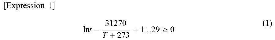
[0073] During slab heating, segregation generated during casting remains, and upon subsequent rolling, the segregation changes to a band-like uneven structure (or texture) in the sheet thickness direction. Since this structure can have an adverse effect on weldability in some cases, it is more desirable to satisfy Expression (1) below in order to reduce the effect of segregation.
[ Expression 1 ] ln t - 31270 T + 273 + 11.29 .gtoreq. 0 ( 1 ) ##EQU00001##
[0074] where, t is a heating time (unit: seconds), and T is a heating temperature (unit: .degree. C.). Expression (1) is an experimentally determined conditional expression for reducing the adverse effect of Mn segregation that causes band-like uneven texture in slab heating. When the left side of Expression (1) is 0 or more, Mn diffuses during slab heating such that adverse effects on weldability due to formation of band-like uneven texture are reduced. In addition, while the upper limit of the left side of the Expression (1) is not particularly limited, in many cases, it is 1.00 or less in consideration of producibility.
[0075] Finish Rolling Temperature: 820.degree. C. or Higher
[0076] When a finish rolling temperature is lower than 820.degree. C., transformation from austenite to ferrite starts during rolling, and the local strength of the steel sheet fluctuates, resulting in degraded accuracy of the sheet thickness by the cold rolling in the subsequent step. Therefore, the finish rolling temperature is 820.degree. C. or higher. Preferably, it is 840.degree. C. or higher. More preferably, it is 850.degree. C. or higher. In addition, the upper limit of the finish rolling temperature is substantially 1020.degree. C. due to restrictions associated with the production facilities, but not particularly limited thereto. Preferably, the upper limit is 1000.degree. C. or lower. More preferably, the upper limit is 950.degree. C. or lower.
[0077] Coiling Temperature: 350.degree. C. or Higher and 680.degree. C. or Lower
[0078] When the coiling temperature is lower than 350.degree. C., a shape of a hot-rolled sheet is degraded, and accuracy of the sheet thickness after cold rolling deteriorates. When the coiling temperature exceeds 680.degree. C., an oxide film which is not removable by pickling is formed on the hot rolled sheet surface, thus impairing the surface appearance after cold rolling. Therefore, the coiling temperature is in a range of 350.degree. C. or higher and 680.degree. C. or lower. Preferably, a lower limit of the coiling temperature is 380.degree. C. or higher. More preferably, it is 400.degree. C. or higher. Preferably, an upper limit of the coiling temperature is 650.degree. C. or lower. More preferably, the coiling temperature is 630.degree. C. or lower. When V, Ti and Nb are added, in order to make the carbide size 20 nm or less, the coiling temperature is preferably 520.degree. C. or lower.
[0079] The cold-rolling step as a subsequent step is a step of cold rolling the hot-rolled sheet after the hot-rolling step. In order to obtain a desired sheet thickness, it is necessary to cold roll the hot-rolled sheet after the hot-rolling step. The cold rolling is generally carried out after pickling, and generally-used conditions may be used for the pickling.
[0080] The rolling ratio for the cold rolling is generally 20% to 80%, but not particularly limited thereto. Preferably, the lower limit is 30% or more. Preferably, the upper limit is 75% or less.
[0081] The subsequent annealing step includes retaining at 840.degree. C. or higher for 30 seconds or more after the cold-rolling step, then cooling to 100.degree. C. or lower at an average cooling rate of 200.degree. C./s or more from a cooling starting temperature to the Ms point; re-heating and retaining at 840.degree. C. or higher for 30 seconds or more, then cooling to (Ms point--100.degree. C.) or lower at an average cooling rate of 20.degree. C./s or more from a cooling starting temperature to the (Ms point--100.degree. C.), and as necessary heating or cooling, and retaining at 200.degree. C. or higher and 400.degree. C. or lower for 20 seconds or more and 1800 seconds or less.
[0082] Retaining at 840.degree. C. or Higher for 30 Seconds or More
[0083] "Retaining at 840.degree. C. or higher for 30 seconds or more" is important for eliminating the influence of the recrystallized structure generated from the structure after cold rolling and for increasing the concentrations of Cr, Mo, Ni, B and Sb in addition to Si and Mn on the prior austenite grain boundary that corresponds to the tempered martensite grain boundary. In order to increase the concentration of Si, Mn, and the like on the grain boundary after obtaining a completely recrystallized structure, it is necessary to retain at 840.degree. C. or higher for 30 seconds or more. When V, Ti and Nb are added, in order to make the carbide size 20 nm or less, the retaining time is preferably 300 seconds or less. Retaining at 840.degree. C. or higher for 50 seconds or more and 280 seconds or less is more preferable. Retaining at 840.degree. C. or higher for 70 seconds or more and 250 seconds or less is still more preferable. In addition, the heating temperature is generally 880.degree. C. or lower.
[0084] Cooling to 100.degree. C. or Lower at Average Cooling Rate of 200.degree. C./s or More from Cooling Starting Temperature to Ms Point
[0085] In the cooling in this step, it is necessary to prevent the grain boundary movement at the austenite/ferrite interface. For that purpose, it is necessary to cool at an average cooling rate of 200.degree. C./s or more from a cooling starting temperature to the Ms point. In order to prevent the formation of ferrite in the cooling process, it is more preferable to set the cooling starting temperature at 820.degree. C. or higher and cool to room temperature by water cooling. The "room temperature" refers to a temperature of 0.degree. C. or higher and 50.degree. C. or lower. The average cooling rate is generally 800.degree. C./s or less. In addition, heating is performed to 840.degree. C. or higher before cooling, but the heating temperature may or may not coincide with the cooling starting temperature. For example, the temperatures may not coincide with each other when the temperature is decreased between end of heating and start of cooling. Further, the cooling rate from the Ms point to the cooling stop temperature is not particularly limited.
[0086] Re-Heating and Retaining at 840.degree. C. or Higher for 30 Seconds or More
[0087] Annealing once at 840.degree. C. or higher into martensite and second time heating at 840.degree. C. or higher provides the effect of preventing the coarsening of the prior austenite grains and decreasing of the grain size of the tempered martensite, while effectively increasing the concentration of elements such as Si and Mn on the grain boundary of the prior austenite. After annealing is completed, it is necessary to retain at 840.degree. C. or higher for 30 seconds or more, because it is necessary to make the structure in which the austenite is main component. Meanwhile, while the upper limit of the retaining time is not particularly limited, when the retaining time at 840.degree. C. or higher exceeds 300 seconds, the austenite grains become coarse, and fine tempered martensite may not be obtained in some cases. Therefore, the retaining at 840.degree. C. or higher is preferably for 280 seconds or less. Retaining at 840.degree. C. or higher for 50 seconds or more and 200 seconds or less is preferable. In addition, the heating temperature is generally 900.degree. C. or lower.
[0088] Cooling to (Ms point--100.degree. C.) or lower at average cooling rate of 20.degree. C./s or more from cooling starting temperature to (Ms Point--100.degree. C.)
[0089] It is necessary to almost complete the transformation from austenite to martensite in this cooling step. When the average cooling rate is low, bainite and ferrite are generated during the cooling process, and the concentration at the grain boundary becomes smaller due to grain boundary migration, which is thus necessary to be prevented as much as possible. For that purpose, it is necessary to cool at the average cooling rate of 20.degree. C./s or more from the cooling starting temperature to (Ms point--100.degree. C.). In addition, when the cooling stop temperature is high, tempered martensite is not generated in the subsequent step, and a desired structure cannot be obtained. In view of the above, it is necessary to cool to at least (Ms point--100.degree. C.) or lower. Preferably, a cooling to 240.degree. C. or lower is performed at an average cooling rate of 30.degree. C./s or more from the cooling starting temperature to (Ms point--100.degree. C.), and the cooling starting temperature is 820.degree. C. or higher. The heating temperature before the start of the cooling and the cooling starting temperature may not coincide with each other. For example, the temperature after heating may slightly decrease until the cooling starts. The average cooling rate is generally 60.degree. C./s or less.
[0090] Retaining at 200.degree. C. or Higher and 400.degree. C. or Lower for 20 Seconds or More and 1800 Seconds or Less
[0091] In order to temper formed martensite, retaining within a predetermined temperature range is necessary. When the retaining temperature is lower than 200.degree. C., tempering does not proceed and formability is poor for practical use. When the temperature is higher than 400.degree. C., coarse iron-based carbides are formed on the tempered martensite grain boundary, which decreases weldability. Therefore, the retaining temperature range is 200.degree. C. or higher and 400.degree. C. or lower. When the retaining time is less than 20 seconds, the tempering does not proceed sufficiently. When it is more than 1800 seconds, the iron-based carbides become coarser. Therefore, the retaining time is 20 seconds or more and 1800 seconds or less. Retaining at 200.degree. C. or higher and 400.degree. C. or lower for 50 seconds or more and 1500 seconds or less is preferable. In addition, when the cooling stop temperature in the cooling before the retaining described above is lower than 200.degree. C., heating is required. Even when the cooling stop temperature is in the range of 200.degree. C. to 400.degree. C., heating or cooling may be performed as needed.
[0092] Next, a method for producing a steel sheet having a coating layer will be described. Since the steps are same as those of the method for producing the steel sheet not having the coating layer until the cold rolling, redundant explanation thereof will be omitted. The method for producing a steel sheet having a coating layer includes a step of heating and retaining at 840.degree. C. or higher for 30 seconds or more, then cooling to 100.degree. C. or lower at an average cooling rate of 200.degree. C./s or more from a cooling starting temperature to 200.degree. C.; re-heating and retaining at 840.degree. C. or higher for 10 seconds or more and 150 seconds or less, then cooling to 260.degree. C. or lower at an average cooling rate of 20.degree. C./s or more from a cooling starting temperature to the 260.degree. C.; and, heating or cooling as necessary, retaining at 200.degree. C. or higher and 400.degree. C. or lower for 20 seconds or more and 150 seconds or less, and a step of subjecting to a coating treatment by immersing in a plating bath, or subjecting to alloying treatment in addition to the coating treatment.
[0093] Retaining at 840.degree. C. or Higher for 30 Seconds or More
[0094] "Retaining at 840.degree. C. or higher for 30 seconds or more" is important for eliminating the influence of the recrystallized structure generated from the structure after cold rolling and for increasing the concentrations of Cr, Mo, Ni, B and Sb in addition to Si and Mn in the prior austenite grain boundary that corresponds to the tempered martensite grain boundary. In order to increase the concentration of Si, Mn, and the like in the grain boundary after obtaining a completely recrystallized structure, it is necessary to retain at 840.degree. C. or higher for 30 seconds or more. When V, Ti and Nb are added, in order to make the carbide size 20 nm or less, the retaining time is preferably 300 seconds or less. More preferably, it is 840.degree. C. or higher for 50 seconds or more and 280 seconds or less. In addition, the heating temperature is generally 880.degree. C. or lower.
[0095] Cooling to 100.degree. C. or lower at average cooling rate of 200.degree. C./s or more from cooling starting temperature to 200.degree. C.
[0096] The state of distribution of the elements in the grain boundary generated by the above annealing is frozen by changing the austenite into the structure in which martensite is the main component, and meanwhile, it is necessary to prevent the formation of coarse iron-based carbide. For that purpose, it is necessary to perform cooling at an average cooling rate of 200.degree. C./s or more from the cooling starting temperature to 200.degree. C. In order to prevent the formation of ferrite, it is more preferable to set the cooling starting temperature to 820.degree. C. or higher and to cool to room temperature by water cooling. The "room temperature" as used herein refers to a temperature of 0.degree. C. or higher and 50.degree. C. or lower. The average cooling rate is generally 800.degree. C./s or less. In addition, heating to 840.degree. C. or higher is performed before cooling, but the heating temperature may or may not coincide with the cooling starting temperature. For example, the temperatures may not coincide with each other when the temperature is decreased from end of heating to start of cooling. Further, the cooling rate from 200.degree. C. to the cooling stop temperature is not particularly limited.
[0097] Reheating and Retaining at 840.degree. C. or Higher for 10 Seconds or More and 150 Seconds or Less
[0098] Annealing once at 840.degree. C. or higher, then changing into martensite and secondly heating at 840.degree. C. or higher provides the effect of preventing the coarsening of the prior austenite grains and the decrease of the grain size of the tempered martensite, while effectively increasing the concentration of elements such as Si and Mn in the grain boundary of the prior austenite. It is necessary to retain at 840.degree. C. or higher for 10 seconds or more, because it is necessary to make the structure in which the austenite is main component at the time when annealing is completed. Meanwhile, with the retaining at 840.degree. C. or higher for the retaining time of 150 seconds or more, the austenite grains become coarse, and fine tempered martensite may not be obtained. Therefore, the retaining at 840.degree. C. or higher for 150 seconds or less is performed. The retaining at 840.degree. C. or higher for 20 seconds or more and 130 seconds or less is preferable. In addition, the heating temperature is generally 900.degree. C. or lower.
[0099] Cooling to 260.degree. C. or lower at average cooling rate of 20.degree. C./s or more from cooling starting temperature to 260.degree. C.
[0100] It is necessary to almost complete the transformation from austenite to martensite in this cooling step. When the average cooling rate is low, bainite and ferrite are generated during the cooling process, and the concentration at the grain boundary becomes smaller due to grain boundary migration, which must be prevented as much as possible. For that purpose, it is necessary to cool at the average cooling rate of 20.degree. C./s or more from the cooling starting temperature to 260.degree. C. In addition, when the cooling stop temperature is high, tempered martensite is not generated in the subsequent step, and a desired structure cannot be obtained. In view of the above, it is necessary to cool to at least 260.degree. C. or lower. Preferably, the cooling to 240.degree. C. or lower is performed at an average cooling rate of 30.degree. C./s or more from the cooling starting temperature to 260.degree. C., and the cooling starting temperature is 820.degree. C. or higher. The heating temperature before the start of the cooling and the cooling starting temperature may not coincide with each other. For example, the temperature after heating may slightly decrease until the cooling starts. The average cooling rate is generally 60.degree. C./s or less.
[0101] Retaining at 200.degree. C. or Higher and 400.degree. C. or Lower for 20 Seconds or More and 150 Seconds or Less
[0102] In order to temper the generated martensite, retaining within a predetermined temperature range is necessary. When the retaining temperature is lower than 200.degree. C., tempering does not proceed and formability is not available in practical use. When the temperature is higher than 400.degree. C., coarse iron-based carbides are formed on the tempered martensite grain boundary, which causes decrease of weldability. Therefore, the retaining temperature range is between 200.degree. C. or higher and 400.degree. C. or lower. When the retaining time is less than 20 seconds, the tempering does not proceed sufficiently. When it is more than 150 seconds, the iron-based carbide becomes coarser. Therefore, the retaining time is 20 seconds or more and 150 seconds or less. Retaining at 200.degree. C. or higher and 400.degree. C. or lower for 50 seconds or more and 130 seconds or less is preferable. In addition, when the cooling stop temperature in the cooling before the retaining described above is lower than 200.degree. C., heating is necessary. Even when the cooling stop temperature is in the range of 200.degree. C. to 400.degree. C., heating and cooling may be performed as needed.
[0103] The plating is performed. As a result, a steel sheet having a coating layer can be produced. The specific method of the coating treatment is not particularly limited, and may be either hot-dip plating or electroplating.
[0104] In the case of hot-dip plating, due to immersion in a plating bath, and also alloying that is performed as necessary, the steel sheet is temporarily exposed to a temperature higher than 400.degree. C. In consideration of this influence, it is necessary to adjust the time of retaining at 200.degree. C. or more and 400.degree. C. or lower before coating. Therefore, when manufacturing a steel sheet having a coating layer, the retaining time is 20 seconds or more and 150 seconds or less. Preferably, it is 30 seconds or more and 130 seconds or less.
Examples
[0105] Hot-rolling step was performed on a steel material having a composition shown in Table 1 and having a thickness of 250 mm under hot rolling conditions shown in Table 2 to obtain a hot rolled steel sheet, the hot-rolled steel sheet was subjected to cold rolling in which the cold rolling ratio is 29% or more and 68% or less to obtain a cold-rolled steel sheet, and then the cold-rolled steel sheet was subjected to annealing under the conditions shown in Table 2 on a continuous annealing line or continuous hot-dip plating line. The coating treatment and, if necessary, alloying treatment were then carried out. In this Example, the temperature of the plating bath (plating composition: Zn-0.13 mass % Al) used for immersion in the continuous molten plating line was 460.degree. C. and coating weight of GI material (hot-dip plated steel sheet) and of GA material (alloyed hot-dip plated steel sheet) were 45 to 65 g/m.sup.2 per side, and an amount of Fe contained in the coating layer of the GA material was in a range of 6 to 14 mass %.
The Ms point was obtained by the Expression (2).
Ms point (.degree. C.)=561-474.times.[C]-33.times.[Mn]-17.times.[Ni]-17.times.[Cr]-21.times.- [Mo]. (2)
where, [M] (M=C, Mn, Ni, Cr, Mo) is the weight concentration of alloying elements.
TABLE-US-00001 TABLE 1 Steel Chemical Composition (mass %) No. C Si Mn P S Al N V Ti Nb Cr A 0.13 1.25 2.65 0.01 0.003 0.03 0.0026 B 0.13 1.52 2.82 0.01 0.002 0.03 0.0025 C 0.18 1.53 3.15 0.01 0.002 0.03 0.0029 D 0.14 1.15 2.71 0.01 0.001 0.03 0.0025 0.34 E 0.13 1.45 2.77 0.01 0.002 0.04 0.0032 0.11 F 0.12 1.51 2.74 0.02 0.002 0.03 0.0022 0.07 G 0.09 1.15 2.25 0.01 0.001 0.04 0.0020 0.68 H 0.11 1.20 2.21 0.02 0.001 0.03 0.0020 I 0.10 1.15 2.13 0.02 0.001 0.05 0.0032 0.15 J 0.13 0.91 2.34 0.01 0.001 0.03 0.0022 0.36 K 0.17 1.52 2.97 0.01 0.002 0.04 0.0024 L 0.18 1.53 2.75 0.02 0.002 0.05 0.0032 0.02 0.07 M 0.09 1.01 2.34 0.02 0.001 0.03 0.0033 0.02 0.35 N 0.11 1.53 2.75 0.02 0.003 0.03 0.0034 0.10 0.03 0.02 0.31 O 0.06 1.31 2.32 0.02 0.002 0.03 0.0030 P 0.13 0.23 2.75 0.02 0.001 0.05 0.0020 0.21 Q 0.12 1.06 1.55 0.01 0.002 0.05 0.0020 Steel Chemical Composition (mass %) Ms Point No. Mo Ni B Sb Others .degree. C. Remarks A 412 Example B 406 Example C 372 Example D 405 Example E 408 Example F 414 Example G 433 Example H 0.34 429 Example I 0.2 437 Example J 0.11 414 Example K 0.26 0.03 376 Example L 0.25 0.04 0.0015 378 Example M 0.05 REM: 0.002 435 Example Ca: 0.001 N 0.43 0.31 0.0012 0.01 Sn: 0.01 399 Example Mg: 0.02 O 456 Comparative example P 405 Comparative example Q 0.28 0.35 441 Comparative example Values outside the range of the present invention are underlined.
TABLE-US-00002 TABLE 2 Hot rolling process Finish Cold Annealing process Slab Left rolling rolling Re-heat Cooling Cooling Cooling Steel heating side of finishing Coiling reduction Heating retaining starting rate stop sheet temp Expression temp temp rate temp time temp (.degree. C./s) temp No. Steel Surface (.degree. C.) (1) (.degree. C.) (.degree. C.) (%) (.degree. C.) (s) (.degree. C.) .asterisk-pseud.1 (.degree. C.) 1 A CR 1260 0.05 920 630 60 841 36 835 291 17 2 GI 1230 0.10 910 610 53 861 173 844 667 29 3 GA 1270 0.35 930 540 66 845 189 837 461 39 4 CR 1230 0.24 850 480 65 812 117 801 265 23 5 CR 1250 0.33 920 650 68 860 18 842 252 36 6 CR 1230 0.40 880 500 40 860 263 846 45 22 7 CR 1240 0.10 840 480 42 864 260 848 655 28 8 CR 1260 0.40 880 620 51 863 247 848 348 34 9 GA 1240 0.26 880 500 53 865 102 844 335 35 10 CR 1230 0.28 910 550 38 846 145 836 519 31 11 CR 1260 0.39 870 520 29 845 319 839 345 10 12 GA 1240 0.15 850 610 40 841 166 831 438 23 13 B CR 1230 0.25 860 540 66 852 158 836 539 37 14 GI 1240 0.17 870 560 62 847 203 835 425 32 15 GA 1240 0.08 930 570 63 859 216 840 620 35 16 C CR 1270 0.34 930 570 43 849 87 837 639 21 17 GI 1230 0.13 930 460 68 843 326 838 562 29 18 GA 1240 0.22 840 500 67 846 140 834 514 15 19 D CR 1240 0.07 900 490 46 848 105 838 636 33 20 GI 1260 0.19 840 480 40 853 222 840 494 22 21 GA 1230 0.30 870 470 32 842 293 837 259 33 22 E CR 1230 0.17 870 490 58 852 78 839 487 17 23 GI 1230 0.39 870 500 65 844 72 834 639 27 24 GA 1270 0.13 880 510 64 844 161 832 397 33 25 F CR 1230 0.40 860 480 56 846 144 833 288 18 26 GI 1260 0.30 850 500 45 860 262 844 278 32 27 GA 1230 0.21 870 520 63 842 250 832 361 30 28 G CR 1240 0.16 900 460 67 853 138 838 568 37 29 GI 1260 0.14 860 640 33 854 127 838 444 25 30 GA 1250 0.40 910 590 52 864 315 848 270 21 Annealing process Re-heating Cooling Cooling Cooling Heating Retaining Steel Re-heating retaining starting rate stop temp. for time for sheet temp time temp (.degree. C./s) * temp tempering tempering No. Steel Surface (.degree. C.) (S) (.degree. C.) * .asterisk-pseud.2 (.degree. C.) * (.degree. C.) (s) Remarks 1 A CR 851 105 839 35 178 270 732 Ex. 2 GI 853 64 837 34 160 290 53 Ex. 3 GA 850 24 837 49 201 230 86 Ex. 4 CR 853 74 837 33 182 260 952 Com. Ex. 5 CR 865 99 848 42 182 370 110 Com. Ex. 6 CR 841 45 834 46 180 260 154 Com. Ex. 7 CR 826 105 810 47 174 370 735 Com. Ex. 8 CR 841 5 834 27 187 340 472 Com. Ex. 9 GA 854 362 834 29 204 360 83 Com. Ex. 10 CR 859 37 835 42 196 460 120 Com. Ex. 11 CR 859 46 842 33 193 250 2540 Com. Ex. 12 GA 846 35 838 26 198 340 198 Com. Ex. 13 B CR 861 71 845 39 180 310 695 Ex. 14 GI 862 117 836 46 161 350 104 Ex. 15 GA 841 41 836 30 170 290 74 Ex. 16 C CR 853 74 839 48 168 260 665 Ex. 17 GI 863 40 840 35 187 380 63 Ex. 18 GA 848 98 838 43 186 210 62 Ex. 19 D CR 859 49 842 39 167 360 657 Ex. 20 GI 864 79 839 27 196 230 96 Ex. 21 GA 844 82 827 47 161 330 88 Ex. 22 E CR 846 118 833 42 196 300 148 Ex. 23 GI 842 44 830 44 210 340 69 Ex. 24 GA 850 71 834 39 177 370 107 Ex. 25 F CR 858 112 838 34 200 350 494 Ex. 26 GI 859 50 839 40 182 240 96 Ex. 27 GA 853 118 835 44 165 310 49 Ex. 28 G CR 859 107 837 50 194 230 111 Ex. 29 GI 856 51 836 40 170 290 36 Ex. 30 GA 861 118 846 42 199 230 111 Ex. Hot rolling process Finish Cold Annealing process Slab Left rolling rolling Re-heat Cooling Cooling Cooling Steel heat side of finishing Coiling reduction Heat retaining start rate stop sheet temp Expression temp temp rate temp time temp (.degree. C./s) temp No. Steel Surface (.degree. C.) (1) (.degree. C.) (.degree. C.) (%) (.degree. C.) (s) (.degree. C.) .asterisk-pseud.1 (.degree. C.) 31 H CR 1230 0.22 890 500 65 864 280 842 758 24 32 CR 1180 -0.74 860 590 45 850 147 841 659 22 33 GI 1270 0.10 920 620 43 861 63 846 508 14 34 GA 1270 0.15 890 640 66 840 183 832 345 27 35 I CR 1260 0.28 890 570 56 847 291 837 532 33 36 GI 1230 0.18 850 540 39 850 306 839 650 39 37 GA 1270 0.16 840 570 62 861 110 844 637 34 38 J CR 1260 0.41 930 550 61 850 280 840 376 17 39 GI 1240 0.19 880 600 57 859 258 840 624 14 40 GA 1270 0.21 870 530 67 860 317 845 329 34 41 K CR 1240 0.09 900 610 46 852 64 839 271 17 42 GI 1260 0.35 860 570 60 857 103 841 370 16 43 GA 1250 0.09 920 540 32 863 294 842 382 24 44 L CR 1240 0.40 900 490 40 848 129 840 643 21 45 GI 1230 0.22 860 510 53 850 254 835 274 15 46 GA 1270 0.14 860 480 40 862 329 841 629 33 47 M GA 1240 0.27 880 500 58 846 236 834 753 16 48 N GA 1240 0.29 880 440 34 842 194 835 462 17 49 O CR 1260 0.32 880 590 49 855 260 840 316 37 50 P CR 1250 0.24 930 500 35 858 219 840 673 40 51 Q CR 1270 0.25 840 590 40 853 204 843 651 28 Annealing process Re-heat Cooling Cooling Cooling Heating Retaining Steel Re-heat retaining start rate stop temp for time for sheet temp time temp (.degree. C./s) * temp tempering tempering No. Steel Surface (.degree. C.) (s) (.degree. C.) * .asterisk-pseud.2 (.degree. C.) * (.degree. C.) (s) Remarks 31 H CR 848 58 838 30 163 310 272 Ex. 32 CR 850 95 834 48 200 300 518 Ex. 33 GI 849 88 830 50 205 250 101 Ex. 34 GA 847 109 832 26 191 320 114 Ex. 35 I CR 845 100 836 38 163 230 132 Ex. 36 GI 851 120 832 35 199 360 41 Ex. 37 GA 856 29 841 50 193 360 118 Ex. 38 J CR 857 103 843 26 192 220 550 Ex. 39 GI 842 32 832 25 189 250 67 Ex. 40 GA 843 85 837 44 192 280 66 Ex. 41 K CR 846 79 830 40 190 230 467 Ex. 42 GI 855 107 833 32 170 210 96 Ex. 43 GA 862 43 841 35 204 270 59 Ex. 44 L CR 848 57 838 47 189 230 884 Ex. 45 GI 848 27 835 39 173 280 30 Ex. 46 GA 863 40 837 26 162 360 116 Ex. 47 M GA 857 64 840 25 191 290 46 Ex. 48 N GA 858 27 840 46 204 320 30 Ex. 49 O CR 847 91 834 26 200 350 876 Com. Ex. 50 P CR 857 50 835 49 198 220 261 Com. Ex. 51 Q CR 851 47 839 45 183 220 428 Com. Ex. Values outside the range of the present invention are underlined. *Cooling condition after reheating .asterisk-pseud.1: Average cooling rate from a cooling starting temperature to a MS point in the case of without the coating layer Average cooling rate from a cooling starting temperature to 200.degree. C. in the case of with the coating layer .asterisk-pseud.2: Average cooling rate from a cooling starting temperature to (MS point - 100.degree. C.) in the case of not having the coating layer Average cooling rate from a cooling starting temperature to 200.degree. C. in the case of having the coating layer
[0106] Test samples were taken from cold-rolled steel sheet (CR material), hot-dip galvanized steel sheet (GI material) or hot-dip galvannealed steel sheet (GA material) obtained as described above and evaluated by the following method.
[0107] Structure Observation
[0108] Area fraction of each of the phases was evaluated by the following method. Test samples were taken from a steel sheet so that a cross-section parallel to the rolling direction may be used as an observation surface and a portion of the center of the sheet thickness was exposed by etching with 1% nital, and then a 1/4t position (t is a total thickness) was photographed under a scanning type electron microscope at a magnification ratio of 2000 with 10 visual fields. The ferrite phase is a structure in which corrosion marks and iron-based carbides are not observed in the grains, and the tempered martensite is a structure in which a large number of minute iron-based carbides and corrosion marks having orientation are observed in the grains. The area fractions of the ferrite phase, the tempered martensite, and the other structures were determined and the results are shown in Table 3.
[0109] The grain size of the tempered martensite was obtained by image analysis using image analysis software (Image-Pro Plus ver. 7.0, manufactured by Nippon Rapor Co., Ltd.). Table 3 shows the average values of the grain sizes. For the image analysis, the photographs obtained with 10 visual fields during the measurement of the area fractions described above were used. The diameter of the circle having the same area as the area of a martensite grain was regarded as the martensite grain size, and the average value of the grain sizes was calculated.
[0110] The average particle size of the carbides (iron-based carbides or carbides including V, Ti and Nb) was determined by measuring the number and percentage of the carbides using a transmission electron microscope. The central portion in the plate thickness direction of the steel sheet was used as a target of observation, and with 300000-fold magnification, 300 carbides were randomly selected from the carbides on the tempered martensite grain boundary to determine the average particle size (or diameter). An energy dispersive X-ray analyzer attached to TEM was used for the identification of carbides. In addition, identification of the grain boundary was performed with 5000-fold by locating the grain boundaries of tempered martensites adjacent to each other, and a portion of the grain boundary identified was photographed by the method described above.
[0111] In order to investigate the element concentration (atomic concentration) of the tempered martensite grain boundary, a prism test sample of 0.5 mm.times.0.5 mm.times.25 mm was taken from the central portion of the sheet thickness in a direction parallel to the sheet thickness direction, at a position across the tempered martensite, and was electrolytically polished to prepare a test sample for measurement having an acicular tip. The element concentration present at the grain boundary was analyzed using a three-dimensional atom probe field ion microscope. The atomic concentrations of Si, Mn, Cr, Mo, Ni, B and Sb were obtained at the grain boundary having a width of .+-.0.25 nm away from the position where the element concentration was the maximum. Further; the grain boundary line was identified by way of analyzing C and regarding a portion with the highest C concentration as the grain boundary line.
[0112] Tensile Test
[0113] A JIS No. 5 tensile test sample was prepared from the steel sheet obtained in a direction perpendicular to the rolling direction and subjected to a tensile test five times according to the provision of JIS Z 2241 (2011) to obtain respective average values of yield strength (YS), a tensile strength (TS) and total elongation (El). The crosshead speed of the tensile test was 10 mm/min. In Table 3, the mechanical properties of the steel sheet required for the steel according to aspects of the present invention include the tensile strength: 900 MPa or higher.
[0114] Spot Welding Evaluation
[0115] For the evaluation of weldability, a plated steel sheet of JAC 270C having a sheet thickness of 1.0 mm according to the Japan Iron and Steel Federation Standard JFS A 3011: 2014 was overlapped with the steel according to aspects of the invention or the comparative steel and subjected to spot welding. As welding conditions, a dome radius type chromium copper electrode with a tip diameter of 7 mm.PHI. was used, with a welding time of 25 cycles (60 Hz), a pressing force of 300 kgf, and a nugget diameter of 6 mm. After welding with the different angles between the normal direction of the steel plate and the electrode being 10.degree. and 15.degree., the cross-sectional structure of the welded portion in each case was observed and the presence or absence of cracks was observed. In the case where cracks of 10 .mu.m or more occurred, "x" was given as failure, and otherwise, ".largecircle." is given as "pass", and the results are shown in Table 3.
[0116] In all the examples of the present invention, it is understood that the tensile strength TS was 900 MPa or higher, and excellent weldability was obtained. Meanwhile, in the Comparative Examples outside the scope of the present invention, the tensile strength of 900 MPa was not achieved or excellent weldability evaluation was not obtained.
TABLE-US-00003 TABLE 3 Steel sheet structure Tem- Other pered struc- Tem- Total Carbide Fer- martens- ture pered Atomic Iron- concen- particle Mechanical properties rite ite area martens- concen- based tration size in- of steel sheet Weldability area area frac- ite tration carbide of M cluding Elon- Eval- Eval- frac- percent- tion grain of Si + grain atom N atoms Yield Tensile ga- uation uation Steel tion age (%) size Mn size (atom %) (nm) strength strength tion 1 2 No. (%) (%) *1 (.mu.m) (atom %) (nm) *2 *3 (MPa) (MPa) (%) *4 *5 Remarks 1 17 83 0 3.2 6 30 -- -- 713 903 15 .smallcircle. x Ex. 2 24 71 5 2.8 11 61 -- -- 686 915 16 .smallcircle. .smallcircle. Ex. 3 4 96 0 3.0 7 37 -- -- 636 908 16 .smallcircle. .smallcircle. Ex. 4 13 86 1 2.0 3 51 -- -- 642 904 16 x x Com. Ex. 5 0 97 3 3.4 4 40 -- -- 691 909 15 x x Com. Ex. 6 25 73 2 3.4 4 48 -- -- 743 917 16 x x Com. Ex. 7 45 54 1 2.0 3 42 -- -- 658 866 17 x x Com. Ex. 8 28 69 3 2.7 4 39 -- -- 775 901 16 x x Com. Ex. 9 2 98 0 5.8 8 39 -- -- 717 919 15 x x Com. Ex. 10 1 95 4 1.8 7 125 -- -- 651 857 17 x x Com. Ex. 11 0 100 0 2.3 8 117 -- -- 621 887 16 x x Com. Ex. 12 10 88 2 1.8 12 108 -- -- 750 893 16 x x Com. Ex. 13 9 90 1 2.7 7 55 -- -- 785 1006 15 .smallcircle. x Ex. 14 20 79 1 1.8 7 61 -- -- 805 1006 15 .smallcircle. .smallcircle. Ex. 15 11 89 0 2.5 8 48 -- -- 798 1010 15 .smallcircle. .smallcircle. Ex. 16 7 91 2 2.1 7 47 -- -- 878 1155 13 .smallcircle. x Ex. 17 4 91 5 2.6 8 25 -- -- 870 1160 12 .smallcircle. x Ex. 18 11 89 0 2.5 8 62 -- -- 961 1158 12 .smallcircle. x Ex. 19 4 93 3 2.8 7 31 -- 9 912 1140 12 .smallcircle. x Ex. 20 3 92 5 3.7 7 23 -- 13 936 1141 13 .smallcircle. x Ex. 21 15 84 1 2.6 12 65 -- 8 908 1149 12 .smallcircle. .smallcircle. Ex. 22 1 94 5 3.7 10 53 -- 10 813 1029 14 .smallcircle. .smallcircle. Ex. 23 15 80 5 3.4 11 33 -- 4 857 1033 14 .smallcircle. .smallcircle. Ex. 24 22 77 1 2.3 9 20 -- 3 818 1022 15 .smallcircle. .smallcircle. Ex. 25 25 70 5 1.9 7 50 -- 3 784 1018 15 .smallcircle. .smallcircle. Ex. 26 14 84 2 3.8 10 33 -- 9 722 1031 14 .smallcircle. .smallcircle. Ex. 27 12 86 2 2.7 9 64 -- 3 855 1030 14 .smallcircle. .smallcircle. Ex. 28 20 75 5 3.8 7 34 -- 6 797 1009 15 .smallcircle. .smallcircle. Ex. 29 3 96 1 2.5 8 53 -- 7 716 1008 15 .smallcircle. .smallcircle. Ex. 30 5 90 5 2.7 12 36 -- 7 716 1009 15 .smallcircle. .smallcircle. Ex. 31 0 95 5 2.5 12 62 12 -- 756 1080 13 .smallcircle. .smallcircle. Ex. 32 0 100 0 2.4 8 61 17 -- 867 1070 13 .smallcircle. x Ex. 33 18 79 3 2.4 10 41 17 -- 872 1077 13 .smallcircle. .smallcircle. Ex. 34 25 70 5 2.2 7 26 9 -- 819 1064 14 .smallcircle. .smallcircle. Ex. 35 3 94 3 3.2 7 64 9 -- 833 1028 15 .smallcircle. .smallcircle.. Ex. 36 21 74 5 1.9 10 59 13 -- 831 1026 15 .smallcircle. .smallcircle. Ex. 37 2 95 3 2.1 10 47 16 -- 854 1029 14 .smallcircle. .smallcircle. Ex. 38 7 91 2 2.0 9 58 7 -- 817 1061 14 .smallcircle. .smallcircle. Ex. 39 6 90 4 2.2 12 58 14 -- 861 1063 14 .smallcircle. .smallcircle. Ex. 40 21 74 5 2.6 11 33 14 -- 838 1061 14 .smallcircle. .smallcircle. Ex. 41 14 85 1 2.3 11 23 14 -- 969 1226 11 .smallcircle. .smallcircle. Ex. 42 15 85 0 2.5 12 49 15 -- 958 1228 13 .smallcircle. .smallcircle. Ex. 43 12 86 2 2.0 8 52 15 -- 965 1222 12 .smallcircle. .smallcircle. Ex. 44 5 95 0 2.0 8 37 9 4 963 1250 13 .smallcircle. .smallcircle. Ex. 45 10 87 3 2.3 8 26 12 10 935 1246 11 .smallcircle. .smallcircle. Ex. 46 5 95 0 2.2 11 23 13 4 977 1237 12 .smallcircle. .smallcircle. Ex. 47 0 99 1 2.6 8 39 10 10 854 1029 14 .smallcircle. .smallcircle. Ex. 48 17 80 3 2.6 7 46 17 12 899 1183 12 .smallcircle. .smallcircle. Ex. 49 8 88 4 2.0 11 38 -- -- 637 806 18 .smallcircle. .smallcircle. Com. Ex. 50 4 96 0 2.8 3 21 13 -- 799 987 15 x x Com. Ex. 51 15 84 1 2.3 3 61 15 -- 703 925 15 x x Com. Ex. .asterisk-pseud.1) Total area fraction of microstructure other than ferrite and tempered martensite .asterisk-pseud.2) Total M atomic concentration (Cr, Mo, Ni, B, and Sb) .asterisk-pseud.3) Average size of carbide particles of N atoms (V, Ti, and Nb) .asterisk-pseud.4) Result of determining cross-sectional structure when the normal direction of the steel sheet and the electrode is at 10.degree. .asterisk-pseud.5) Result of determining cross-sectional structure when the normal direction of the steel sheet and the electrode is at 15.degree. The underlines indicate the ranges are outside the present invention.
[0117] All the Examples of the present invention satisfy the weldability evaluation 1. Meanwhile, under the welding condition 2 as a more severe condition, the example at the level satisfying the preferable range of the slab heating condition in addition to the controlled grain boundary atom concentrations of Cr, Mo, Ni, B and Sb obtained excellent evaluations.
* * * * *
uspto.report is an independent third-party trademark research tool that is not affiliated, endorsed, or sponsored by the United States Patent and Trademark Office (USPTO) or any other governmental organization. The information provided by uspto.report is based on publicly available data at the time of writing and is intended for informational purposes only.
While we strive to provide accurate and up-to-date information, we do not guarantee the accuracy, completeness, reliability, or suitability of the information displayed on this site. The use of this site is at your own risk. Any reliance you place on such information is therefore strictly at your own risk.
All official trademark data, including owner information, should be verified by visiting the official USPTO website at www.uspto.gov. This site is not intended to replace professional legal advice and should not be used as a substitute for consulting with a legal professional who is knowledgeable about trademark law.