Model Car Racing Track
Koker; Christian ; et al.
U.S. patent application number 16/349136 was filed with the patent office on 2019-09-05 for model car racing track. The applicant listed for this patent is Stadlbauer Marketing + Vertrieb GmbH. Invention is credited to Christian Koker, Christian Rathge.
| Application Number | 20190270025 16/349136 |
| Document ID | / |
| Family ID | 57583788 |
| Filed Date | 2019-09-05 |


| United States Patent Application | 20190270025 |
| Kind Code | A1 |
| Koker; Christian ; et al. | September 5, 2019 |
MODEL CAR RACING TRACK
Abstract
A model car racetrack with at least one model car which is guided along a lane, a roadway which defines the lane, wherein the roadway has at least one bus bar which extends in the direction of the lane, and a transformer arrangement comprising a primary element and a secondary element for contact-free energy transmission from the roadway to the model car, wherein the bus bar is the primary element of the transformer arrangement and the model car represents the secondary element of the transformer arrangement for coupling in the electromagnetic field which is produced by the primary element.
| Inventors: | Koker; Christian; (Mahlwinkel, DE) ; Rathge; Christian; (Irxleben, DE) | ||||||||||
| Applicant: |
|
||||||||||
|---|---|---|---|---|---|---|---|---|---|---|---|
| Family ID: | 57583788 | ||||||||||
| Appl. No.: | 16/349136 | ||||||||||
| Filed: | November 21, 2017 | ||||||||||
| PCT Filed: | November 21, 2017 | ||||||||||
| PCT NO: | PCT/EP2017/001362 | ||||||||||
| 371 Date: | May 10, 2019 |
| Current U.S. Class: | 1/1 |
| Current CPC Class: | A63H 18/12 20130101; A63H 30/04 20130101 |
| International Class: | A63H 18/12 20060101 A63H018/12; A63H 30/04 20060101 A63H030/04 |
Foreign Application Data
| Date | Code | Application Number |
|---|---|---|
| Nov 22, 2016 | DE | 20 2016 007 185.9 |
Claims
1. A model car racing track having at least one model car guided along a lane and a track defining the lane, wherein the track has at least one bus_bar extending in the direction of the lane, including a transformer arrangement with a primary element and a secondary element for contact-free and interruption-free transmission of energy and control signals from the track to the model car, wherein the bus_bar is arranged on a surface of the track and is the primary element of the transformer arrangement extending in the direction of the lane, and the model car comprises the secondary element of the transformer arrangement for coupling in the electromagnetic field generated by the primary element, wherein the secondary element has a winding or a plurality of windings, wherein the winding or plurality of windings defines a screw vector (S) extending horizontally in a width direction Y which extends substantially at right angles to the direction of the lane.
2. The model car racing track of claim 1, wherein a rotation vector (R) of the electromagnetic field generated by the primary element points substantially in the direction of the lane.
3. The model car racing track of claim 1, wherein the secondary element has a main direction of extension (H) which is substantially at right angles to the direction of the lane.
4. (canceled)
5. The model car racing track of claim 1, wherein at least one second lane with at least one second bus_bar is provided, along which a second model car is guided along the lane, wherein an electrical current with a first frequency is applied to the first bus_bar and a second electrical current with a second frequency is applied to the second bus_bar, wherein the first frequency is different from the second frequency.
6. The model car racing track of claim 5, wherein the second frequency is at least one and a half times the first frequency.
7. The model car racing track of claim 5, wherein the first frequency is 400 kHz and the second frequency 600 kHz.
8. The model car racing track of claim 1, wherein the at least one lane has two parallel bus_bars extending in the direction of the lane.
9. The model car racing track of claim 8, wherein the two bus_bars of a lane are wired electrically in parallel.
10. The model car racing track of claim 8, wherein the two bus_bars of a lane are wired electrically in series.
11. The model car racing track of claim 7, wherein the at least one lane has two parallel bus bars extending in the direction of the lane.
12. The model car racing track of claim 11, wherein the two bus bars of a lane are wired electrically in parallel.
13. The model car racing track of claim 11, wherein the two bus bars of a lane are wired electrically in series.
Description
BACKGROUND OF THE INVENTION
1. Field of the Invention
[0001] The invention relates to a model car racing track. More specifically, the invention relates to a model car racing track having a transformer arrangement for contact-free energy transmission from the track to a model car, where the track bus bar represents the primary element of the transformer arrangement, and the model car represents the secondary element for coupling in the electromagnet field generated by the primary element.
2. Description of Related Art
[0002] A model car racing track, also known as a slot-car track or slot track, is a technical apparatus with which electrically-driven model cars can be driven in a guided manner along lanes, wherein a guide keel on the model car engages in a slot on the track.
[0003] The model car racing track comprises a track which can for example be assembled from a plurality of track sections which can be plugged together. The track can have two lanes which in each case possess a slot for guiding a model car and two bus bars for the current supply of the electrical drive of the model vehicles which can be moved along the respective lane. Current collectors on the respective model cars are thereby in contact with the respective bus bar in order to guarantee a transmission of electrical energy. The speed and braking behavior of the respective model car can in each case be controlled using a hand-held controller. However, when driving round a curve for example, due to centrifugal forces acting on the model cars it can happen that the contact between the bus bar and the current collector of the model car is interrupted, with the consequence that the energy supply to the electrical drive of the model car is interrupted and the model car loses speed.
SUMMARY OF THE INVENTION
[0004] The invention is based on the object of showing a way how an interruption-free supply with electrical energy of model cars of such a model car racing track can be guaranteed.
[0005] According to the invention, this object is achieved through a model car racing track of the aforementioned type with the characterizing features of the independent claims. Advantageous embodiments of the invention are described in the further dependent claims.
[0006] The above and other objects, which will be apparent to those skilled in the art, are achieved in the present invention which is directed to a model car racing track having at least one model car guided along a lane and a track defining the lane, wherein the track has at least one bus bar extending in the direction of the lane, including a transformer arrangement with a primary element and a secondary element for contact-free and interruption-free transmission of energy and control signals from the track to the model car, wherein the bus bar is arranged on a surface of the track and is the primary element of the transformer arrangement extending in the direction of the lane, and the model car comprises the secondary element of the transformer arrangement for coupling in the electromagnetic field generated by the primary element, wherein the secondary element has a winding or a plurality of windings, wherein the winding or plurality of windings defines a screw vector (S) extending horizontally in a width direction Y which extends substantially at right angles to the direction of the lane.
[0007] A rotation vector (R) of the electromagnetic field generated by the primary element points substantially in the direction of the lane. The secondary element has a main direction of extension (H) which is substantially at right angles to the direction of the lane.
[0008] At least one second lane with at least one second bus bar is provided, along which a second model car is guided along the lane, wherein an electrical current with a first frequency is applied to the first bus bar and a second electrical current with a second frequency is applied to the second bus bar, wherein the first frequency is different from the second frequency.
[0009] The second frequency is preferably at least one and a half times the first frequency, for example, the first frequency may be 400 kHz and the second frequency may be 600 kHz.
[0010] The at least one lane may have two parallel bus bars extending in the direction of the lane, where the two bus bars of a lane are wired electrically in parallel or wired electrically in series.
BRIEF DESCRIPTION OF THE DRAWINGS
[0011] The features of the invention believed to be novel and the elements characteristic of the invention are set forth with particularity in the appended claims. The figures are for illustration purposes only and are not drawn to scale. The invention itself, however, both as to organization and method of operation, may best be understood by reference to the detailed description which follows taken in conjunction with the accompanying drawings in which:
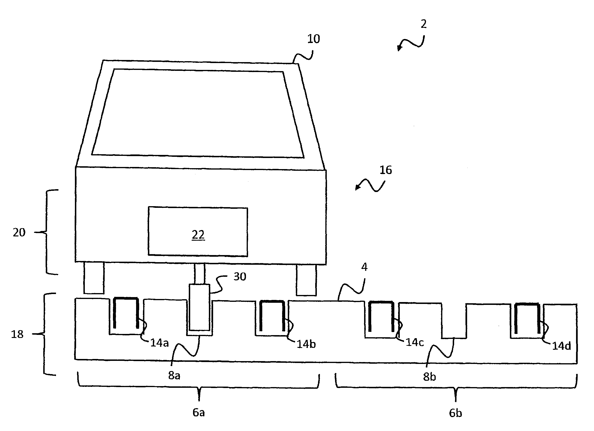
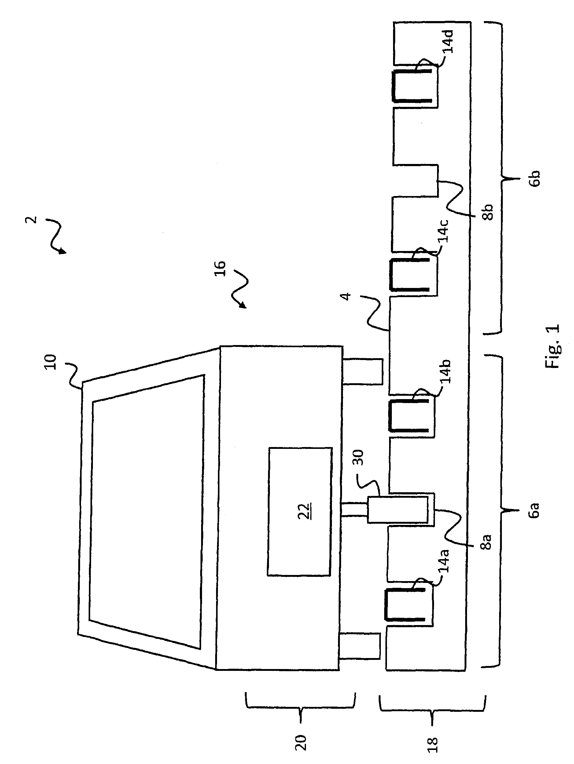
[0012] FIG. 1 shows a schematic sectional representation of a preferred embodiment of a model car racing track according to the invention;
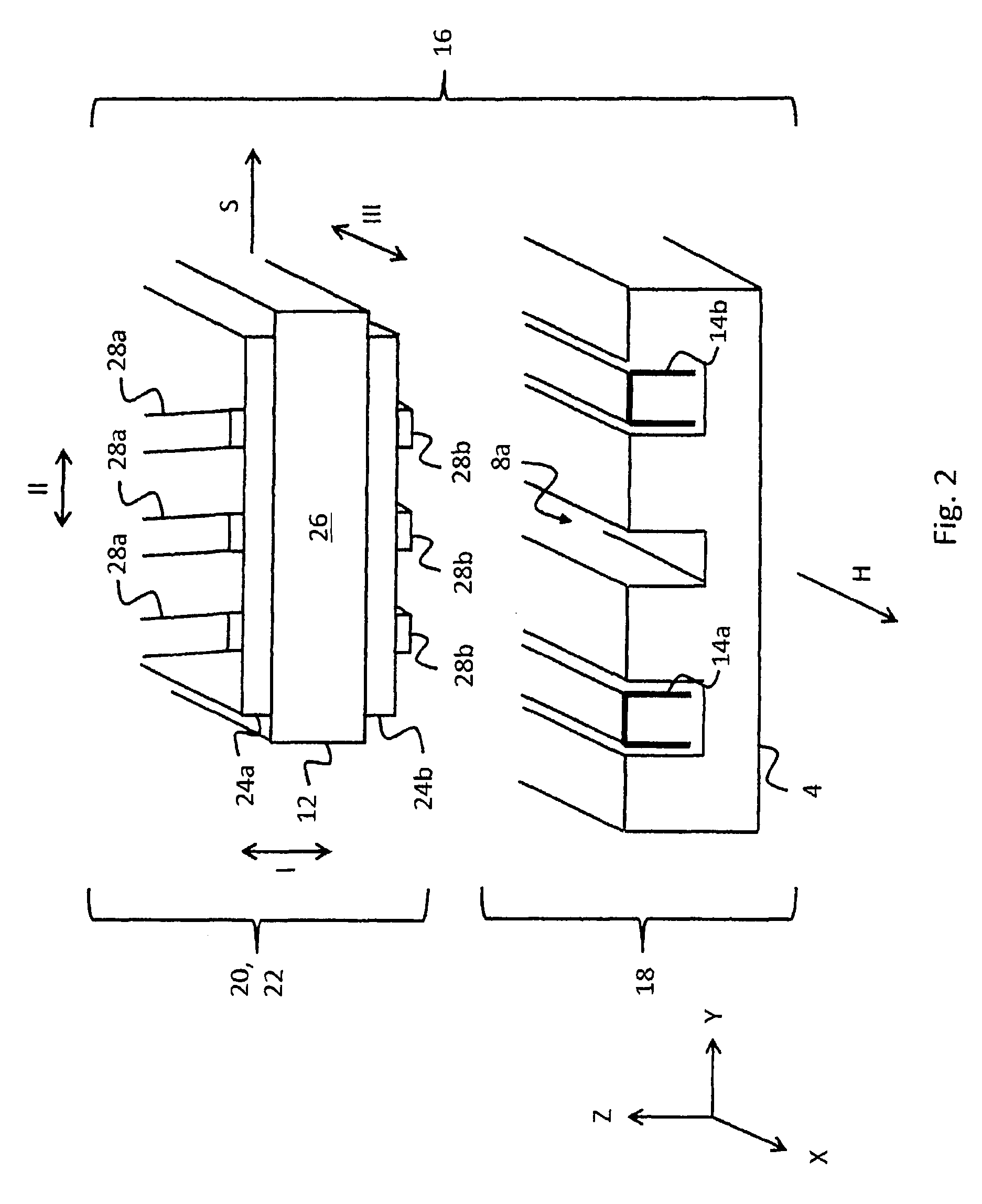
[0013] FIG. 2 shows a schematic representation of a transformer arrangement which is used in the model car racing track shown in FIG. 1;
[0014] FIG. 3 shows a view from above of the first substrate element shown in FIG. 2;
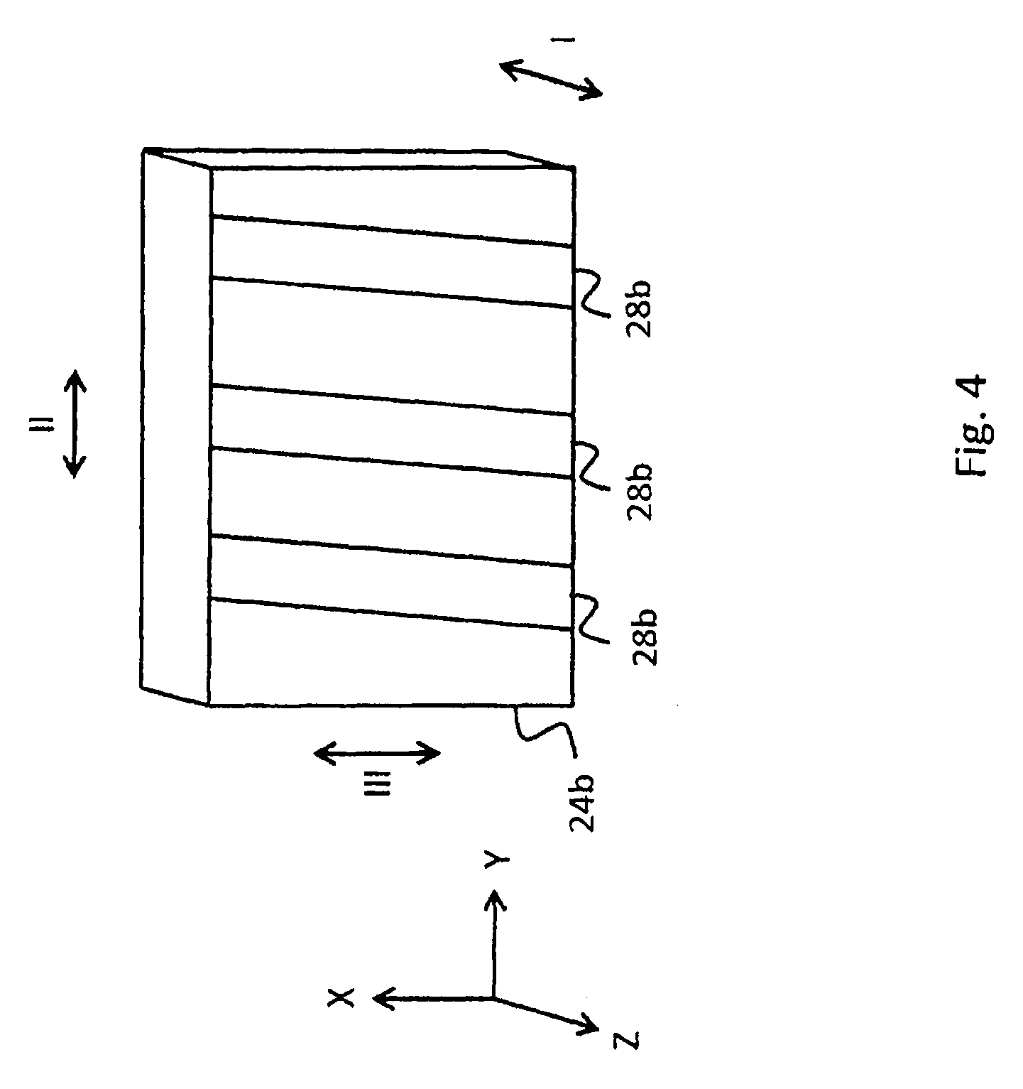
[0015] FIG. 4 shows a view from below of the second substrate element shown in FIG. 2;
[0016] FIG. 5 shows an operating scenario of the model car racing track shown in FIG. 1;
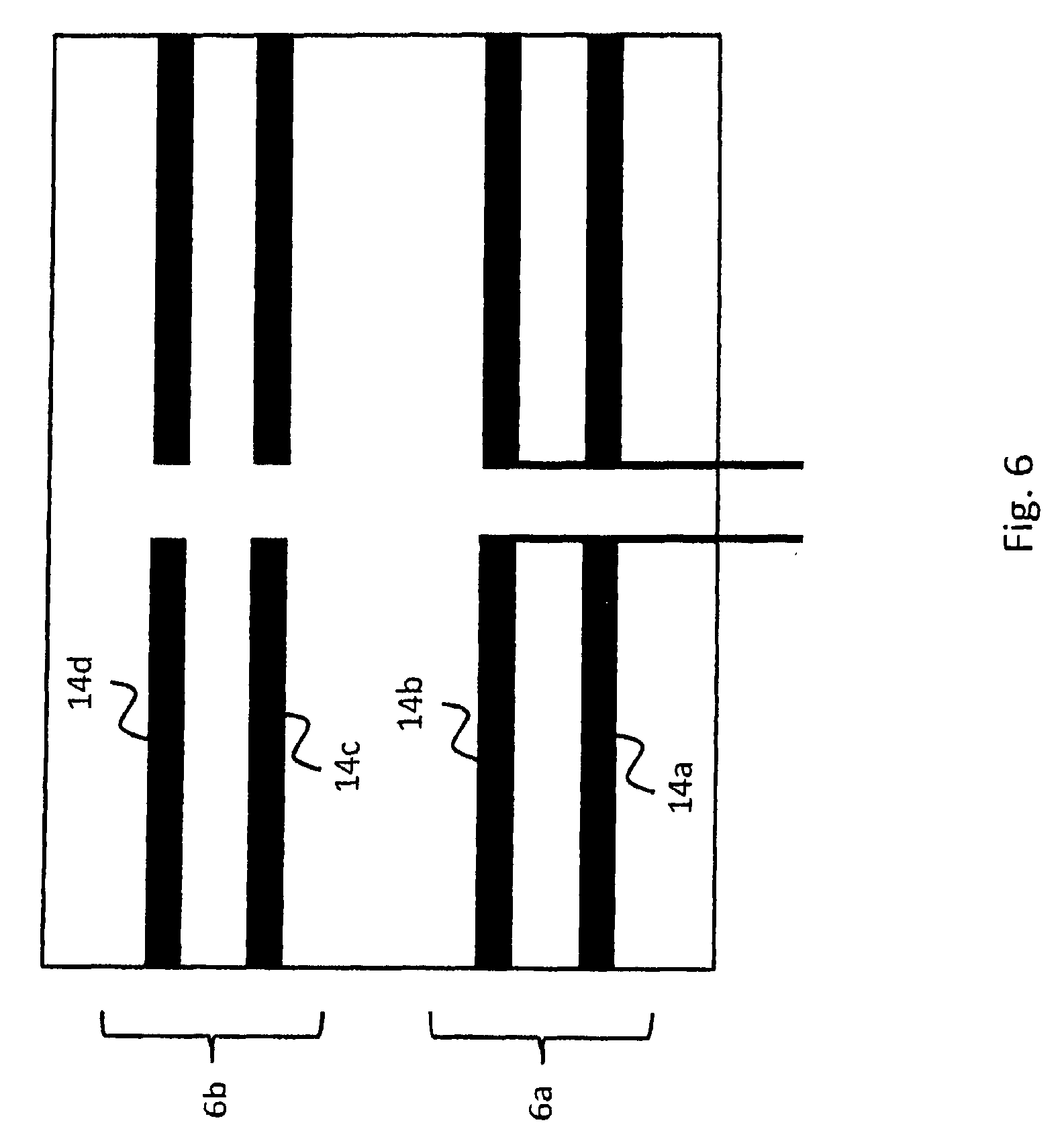
[0017] FIG. 6 shows a first wiring variant of bus bars of a track with two lanes;
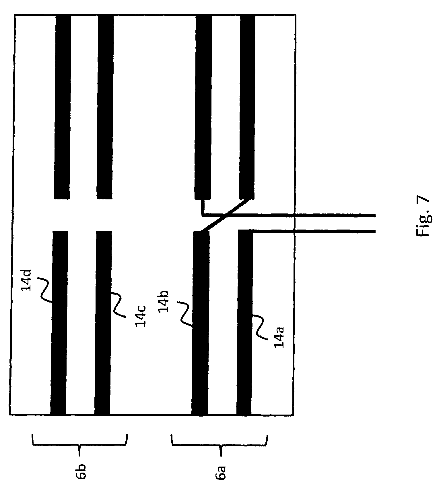
[0018] FIG. 7 shows a second wiring variant of bus bars of a track with two lanes; and
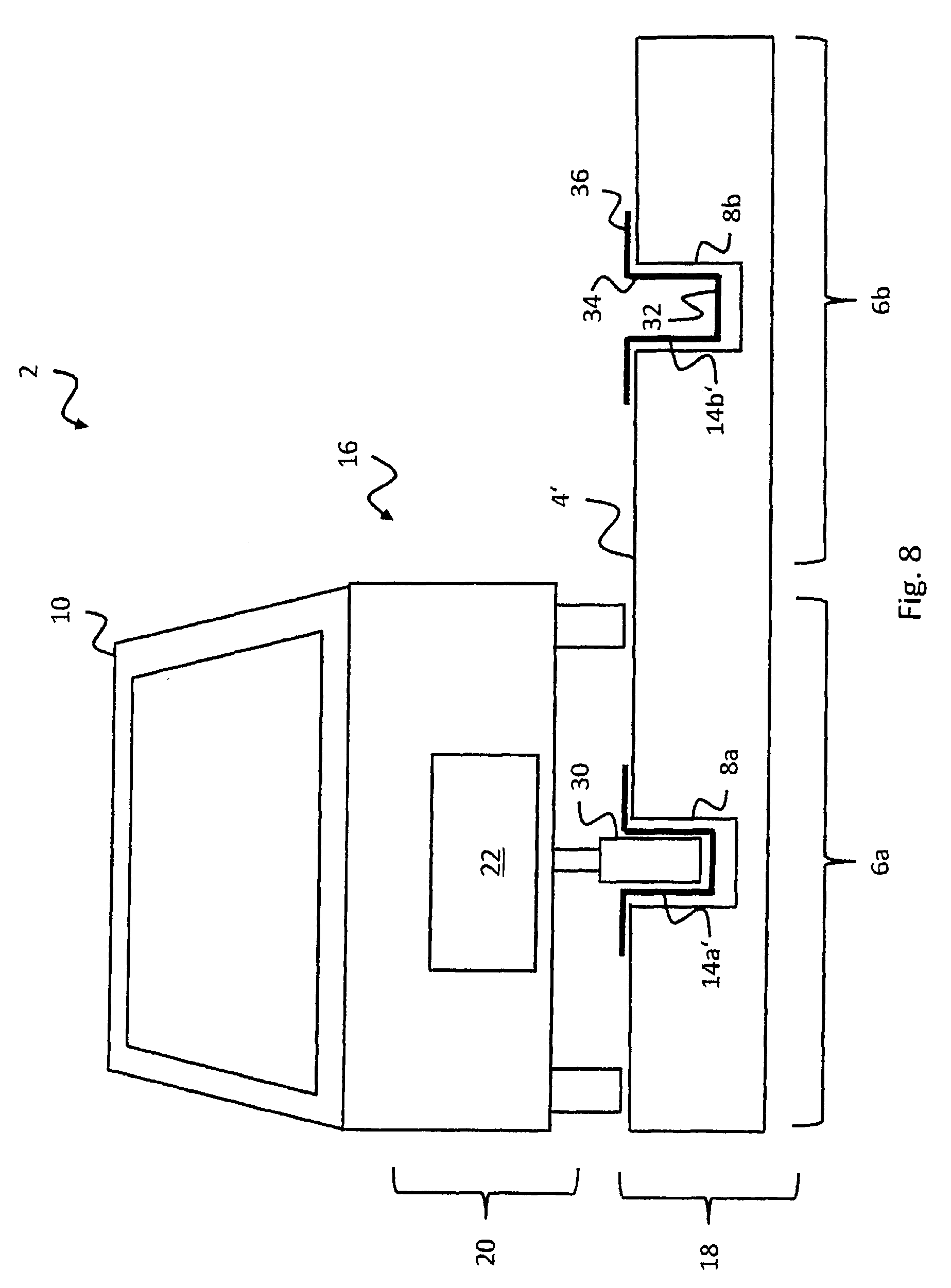
[0019] FIG. 8 shows a further exemplary embodiment of a model car racing track according to the invention, with a track provided with a bus bar for each lane of the track, which has several lanes.
DESCRIPTION OF THE PREFERRED EMBODIMENT(S)
[0020] In describing the preferred embodiment of the present invention, reference will be made herein to FIGS. 1-8 of the drawings in which like numerals refer to like features of the invention.
[0021] For this purpose, in a model car racing track of the aforementioned type, according to the invention a transformer arrangement comprising a primary element and a secondary element for contact-free energy transmission from the track to the model car is provided, wherein the bus bar is the primary element of the transformer arrangement and the model car comprises the secondary element of the transformer arrangement for coupling in the electromagnetic field generated by the primary element. In other words, the model car racing track has an air-core transformer for contact-free energy transmission, wherein the primary element performs the function of a primary coil or winding and the secondary element performs the function of a secondary coil or winding.
[0022] This has the advantage that no temporary interruption of an electrical contact between a bus bar and a current collector, and thus no interruption of the supply with electrical energy, can occur. Furthermore, an unmodified track with a particularly simple structure can be used in which the bus bars are configured as conductors extending in the direction of travel or lane direction. In addition to the transmission of operating energy, control signals can also be transmitted with the transformer arrangement, for example in order to accelerate or brake the model car, for example in that these control signals are modulated with a higher frequency and filtered out again on the model car side.
[0023] According to a preferred embodiment, a rotation vector of the electromagnetic field generated by the primary element points substantially in the direction of the lane. The bus bar, configured as a conductor extended in the direction of the lane, forms a magnetic field, the field lines of which have the form of closed, concentric circles or ellipses around the bus bar. In this case a rotation vector of the magnetic field, which stands perpendicular to the concentric circles, points in the direction of the lane. "Substantially" is thereby understood to mean within usual manufacturing tolerances. Thus, an unmodified track with a particularly simple structure can be used in which the bus bars are configured as conductors extending in the direction of travel or lane direction. Tracks with integrated coil elements, which are complex to manufacture, are not necessary.
[0024] According to a further preferred embodiment, the secondary element has a main direction of extension which is substantially at right angles to the direction of the lane.
[0025] According to a further preferred embodiment, the secondary element has a winding or a plurality of windings, wherein the winding or plurality of windings defines a screw vector which extends substantially at right angles to the direction of the lane. The plurality of windings defines a main direction of extension of the secondary element in the helical direction of the secondary element. Thus, the secondary element can have a different orientation than the primary element, which makes possible a construction-space-saving arrangement within the model car.
[0026] According to a further preferred embodiment, at least one second lane with at least one second bus bar is provided, along which a second model car is guided along the lane, wherein an electrical current with a first frequency is applied to the first bus bar and a second electrical current with a second frequency is applied to the second bus bar, wherein the first frequency is different from the second frequency. In this way, mutual influences through the inductive coupling-in of electrical energy are avoided or at least reduced.
[0027] According to a further preferred embodiment, the second frequency is at least one and a half times the first frequency. In this way, a mutual influence through the inductive coupling-in of electrical energy can be reduced particularly effectively.
[0028] According to a further preferred embodiment, the first frequency is 400 kHz and the second frequency 600 kHz. Through the selection of these frequencies, a particularly effective energy transmission can be achieved on the one hand, and on the other hand minimal interference with other electro-technical or electronic devices in the vicinity of the model car racing track can be achieved.
[0029] According to a further preferred embodiment, the at least one track has two parallel bus bars extending in the direction of the lane. Here too, an unmodified track with a particularly simple structure can be used in which the bus bars are configured as conductors extending in the direction of travel or lane direction.
[0030] According to a further preferred embodiment, the two bus bars are wired electrically in parallel. In this way, a doubled conductor cross section is made available, so that a doubled current strength can be applied to the bus bar elements. Furthermore, this means that, in the event of an interruption of one of the two bus bar elements, electrical current still flows through the other bus bar element. This increases the reliability of the supply of a model car with electrical energy.
[0031] According to a further preferred embodiment, the two bus bar elements are wired electrically in series. Thus, the two bus bar elements form a double loop, which further improves the efficiency of the energy transmission.
[0032] The invention is described in more detail in the following with reference to the drawings.
[0033] A model car racing track 2, also known as a slot-car track or slot track, is represented in FIG. 1.
[0034] The model car racing track 2 has a track 4 made up of a plurality of track sections which can be plugged together with, in the present exemplary embodiment, two lanes 6a, 6b, each for a model car 10. Only one model car 10 is illustrated in FIG. 1.
[0035] In the present exemplary embodiment, the track 4 has a recess 8a, 8b assigned to each lane 6a, 6b which is arranged centrally relative to the lane and in which a guide element 30, for example a guide pin or guide keel of the model car 10, engages and so effects a guidance of the model car 10 along the respective lane, in this case the lane 6a.
[0036] Furthermore, in the present exemplary embodiment the track 4 has in each case two bus bars 14a, 14b, 14c, 14d arranged on each side of the respective recess 8a, 8b which are assigned to the first lane 6a or the second lane 6b. In the present exemplary embodiment, the first and second bus bars 14a, 14b, 14c, 14d have a u-formed profile in cross section and are pressed into further recesses in the track 4. In departure from the present exemplary embodiment, the first and second bus bars 14a, 14b, 14c, 14d can also have a different profile in cross section.
[0037] The bus bars 14a, 14b, 14c, 14d are in each case formed in a single piece and of the same material. Furthermore, the bus bars 14a, 14b, 14c, 14d are manufactured of a magnetic material. In this way, the model car 10 can be held in the lane 6a through magnetic force by means of a permanent magnet (not shown) which interacts with the bus bars 14a, 14b.
[0038] As will be explained later, the two bus bar pairs 14a, 14b or 14c, 14d form a primary element 18 of a transformer arrangement 16 for contact-free energy transmission to the model car 10.
[0039] The transformer arrangement 16 for contact-free energy transmission to the model car 10 also includes a secondary element 20 assigned to the model car 10 for coupling in the electromagnetic field generated by the primary element 18.
[0040] In the present exemplary embodiment, the secondary element 20 is a coil arrangement 22.
[0041] In addition to the transmission of operating energy, control signals can also be transmitted with the transformer arrangement 16, for example in order to accelerate or brake the model car 10, for example in that these control signals are modulated with a higher frequency and filtered out again on the model car side.
[0042] Reference is now made, in addition, to FIG. 2, which for reasons of simplicity only shows the first lane 6a of the two lanes 6a, 6b. However, the following explanations also apply analogously to the second lane 6b with the recess 8b and the bus bars 14c and 14d.
[0043] FIG. 2 shows that both the recess 8a and also the two bus bars 14a, 14b each have a main direction of extension H pointing along the lane 6a in the direction of travel, in which direction its dimensions are significantly greater than in the direction of the other directions of extension.
[0044] Furthermore, FIG. 2 shows that the coil arrangement 22 has a substrate 12. In the present exemplary embodiment, the substrate 12 has a first substrate element 24a and a second substrate element 24b as well as a ferrite core 26 arranged between the first substrate element 24a and the second substrate element 24b.
[0045] In the present exemplary embodiment, the first substrate element 24a and the second substrate element 24b are in each case a circuit board. The circuit boards have a basic shape extending in a planar manner, in the present exemplary embodiment a rectangular basic shape, with in each case an upper side and an underside opposite the upper side. They consist in each case of an electrically insulating material and conductor paths arranged thereon. Fiber-reinforced plastic is for example commonly used as insulating material. The conductor paths are for example etched from a thin coating of copper applied previously to the insulating material.
[0046] In the present exemplary embodiment, conductor paths on the upper side of the first substrate element 24a form a plurality of first coil portions 28a, while in the present exemplary embodiment further conductor paths on the underside of the second substrate element 24b form a plurality of second coil portions 28b. In each case one of the first coil portions 28a and one of the second coil portions 28b together form a coil winding of the coil arrangement 20.
[0047] For this purpose, connecting lines (not shown) are provided which extend through the first substrate element 24a and the second substrate element 24b and connect the respective first coil portions 28a with the respective second coil portion 28b in an electrically conductive manner. Thus, in the present exemplary embodiment the coil portions 28a, 28b form three coil windings. However, five to eight coil windings could also be provided.
[0048] Furthermore, FIG. 2 shows that the ferrite core 26 is arranged with its upper side on an underside of the first substrate element 24a and the underside of the ferrite core 26 is arranged on an upper side of the second substrate element 24b.
[0049] The ferrite core 26 is a component made of ferrite which, as core of the coil arrangement 22, increases its inductance or guides the magnetic field. Ferrites are understood to be materials comprising poorly electrically conductive or non-conductive ferrimagnetic ceramic materials made from the iron oxide haematite (Fe.sub.2O.sub.3), magnetite (Fe.sub.3O.sub.4) and/or from further metal oxides. Depending on the composition, ferrites are hard magnetic or soft magnetic.
[0050] The coil windings formed by the respective first coil portions 28a and second coil portions 28b have a screw vector S which, as illustrated in FIG. 2, lies substantially within the plane of the substrate 12 and describes the helical configuration of the coil windings of the coil arrangement 22.
[0051] It can also be seen that the screw vector S is arranged substantially at right angles to the main direction of extension H of the bus bars 14a, 14b.
[0052] Furthermore, FIG. 2 shows that the substrate 12 has a first direction of extension I, a second direction of extension II and a third direction of extension III.
[0053] In the present exemplary embodiment, the first direction of extension I extends in a height direction Z between the first substrate element 24a and the second substrate element 24b. The second direction of extension II extends at right angles to the first direction of extension I in the direction of the screw vector S or in a width direction Y. Furthermore, the third direction of extension III extends at right angles to the first direction of extension I and to the second direction of extension II in the direction of the main direction of extension H or in a depth direction X.
[0054] In the present exemplary embodiment, the substrate 12, the first substrate element 24a, the second substrate element 24b and the ferrite core 26 in each case have significantly greater dimensions in the direction of the second direction of extension II and the third direction of extension III than in the direction of the first direction of extension I. In other words, they in each case have a rectangular, in particular plate-formed basic shape.
[0055] Reference is now made, in addition, to FIGS. 3 and 4.
[0056] FIGS. 3 and 4 show that the first coil portions 28a and the second coil portions 28b have an elongated form, i.e., their respective dimensions in the direction of the third direction of extension III are greater than in the direction of the second direction of extension II. Furthermore, the first coil portions 28a and the second coil portions 28b extend at an angle to the second direction of extension II which is unequal to a right angle. In the present exemplary embodiment, the first coil portions 28a and the second coil portions 28b extend at an angle of 75.degree. to 85.degree. or 95.degree. to 110.degree. to the second direction of extension II.
[0057] In this way, a coil arrangement 22 is provided which is particularly compact and takes up little construction space. Furthermore, the manufacture of the coil arrangement 22 is simplified in each case through the planar formation of the first coil portions 28a and second coil portion 28b on the upper or underside of the substrate 12, since planar or thick film technology can be used for this purpose.
[0058] The operation of the model car racing track 2 will be explained with additional reference to FIG. 5, wherein, for reasons of simplicity, of the primary element 18, only the first bus bar 14a of the two bus bars 14a, 14b of the first lane 6a is illustrated.
[0059] In operation, an alternating current with a frequency of 400 kHz flows through the bus bar 14a. A magnetic field M is formed around the bus bars 14a with concentric field lines extending around the bus bar 14a. The course of the field lines can be described by a rotation vector R standing perpendicular to the plane which is described by the field lines.
[0060] The field lines pass through the secondary element 20 or the coil arrangement 22 and generate, through induction, an electrical voltage in the secondary element 20. The electrical voltage induced in the secondary element 20 can then be used to supply an electrical drive of the model car 10, so that the model car 10 can move in the direction of travel F predetermined by the main direction of extension H of the recess 8a or the bus bar 14a. Thus, the direction of travel F and the rotation vector R are oriented substantially at right angles to one another. "Substantially" is thereby understood to mean within usual manufacturing tolerances.
[0061] A regulation of the speed of the model car 10 can thereby be achieved through a change in the current strength of the electrical current which flows through the bus bars 14a, 14b.
[0062] Due to the contact-free transmission of electrical energy, contact interruptions, such as occur in the prior art, can be avoided and interruption of the supply with electrical energy no longer occurs.
[0063] In addition to the first lane 6a shown in FIG. 1, in the present exemplary embodiment the second lane 6b for a second model car (not shown) is provided which has the same structure as the first lane 6a. However, in order to avoid, as far as possible, interferences between two model cars 10 and thus disturbances in the energy transmission, the bus bars 14c, 14d of the second lane 6b are flowed through by an electrical current with a frequency which is at least one and a half times as high as the first frequency. In the present exemplary embodiment, the second frequency is 600 kHz.
[0064] Reference is now made, in addition, to FIGS. 6 and 7, which show by way of example wiring variants of the two bus bar pairs 14a, 14b or 14c, 14d with reference to the first lane 6a of the two lanes 6a, 6b of the track 4.
[0065] FIG. 6 shows a first wiring variant in which the two bus bars 14a, 14b of the first lane 6a are wired electrically in parallel. This allows use to be made of the doubled conductor cross section of the two bus bars 14a, 14b, so that a doubling of the current strength applied to the bus bars 14a, 14b becomes possible.
[0066] FIG. 7 shows a second wiring variant in which the two bus bars 14a, 14b of the first lane 6a are wired electrically in series. Thus, the two bus bars 14a, 14b form a double conductor loop, so that the efficiency of the energy transmission is improved.
[0067] Reference is now made to FIG. 8.
[0068] This shows a second exemplary embodiment of a track 4' which, in contrast to the track 4 illustrated in FIG. 1, only has two recesses 8a, 8b, in each of which a further exemplary embodiment of a bus bar 14a', 14b' is fitted.
[0069] The structure of the bus bars 14a', 14b' according to this exemplary embodiment will be explained with reference to the bus bar 14b' assigned to the second lane 6b.
[0070] The bus bar 14b' has a u-formed profile with a groove base 32 and two flanges 34 extending from the groove base 32 which in the present exemplary embodiment extend parallel. Extending from each of the flanges 34 is a tongue 36 which extends within the plane of the surface of the track 4'.
[0071] The bus bars 14a', 14b' according to this exemplary embodiment are in each case formed in a single piece and of the same material. Furthermore, according to this exemplary embodiment the bus bars 14a', 14b' are manufactured of a magnetic material. In this way, here too the model car 10 can be held in the lane 6a through magnetic force by means of a permanent magnet (not shown) which interacts with the bus bar 14a'. In particular, the two tongues 36 provide an enlarged surface on which the magnetic force can act, so that a magnet of reduced size can be used in the model car 10 which takes up less construction space.
[0072] Furthermore, the two bus bars 14a' 14b' are fitted into the respective recesses 8a, 8b such that the u-formed bus bars 14a', 14b' are open in an upwards direction, so that the guide element 30, for example a pin of the model car 10, can engage in the u-formed bus bar 14a' in order in this way to guide the model car 10 along the lane 6a defined by the recess 8a. Thus, this track 4' has a particularly simple structure with only one bus bar 14a', 14b', in the present exemplary embodiment arranged centrally, for each of the lanes 6a, 6b, wherein the bus bars 14a', 14b' in each case have a double function, namely as bus bar and as guide groove for the model car.
[0073] While the present invention has been particularly described, in conjunction with a specific preferred embodiment, it is evident that many alternatives, modifications and variations will be apparent to those skilled in the art in light of the foregoing description. It is therefore contemplated that the appended claims will embrace any such alternatives, modifications and variations as falling within the true scope and spirit of the present invention.
* * * * *
D00000
D00001
D00002
D00003
D00004
D00005
D00006
D00007
D00008
XML
uspto.report is an independent third-party trademark research tool that is not affiliated, endorsed, or sponsored by the United States Patent and Trademark Office (USPTO) or any other governmental organization. The information provided by uspto.report is based on publicly available data at the time of writing and is intended for informational purposes only.
While we strive to provide accurate and up-to-date information, we do not guarantee the accuracy, completeness, reliability, or suitability of the information displayed on this site. The use of this site is at your own risk. Any reliance you place on such information is therefore strictly at your own risk.
All official trademark data, including owner information, should be verified by visiting the official USPTO website at www.uspto.gov. This site is not intended to replace professional legal advice and should not be used as a substitute for consulting with a legal professional who is knowledgeable about trademark law.