Constrainable Stent Graft, Delivery System and Methods of Use
Arbefeuille; Samuel ; et al.
U.S. patent application number 16/414292 was filed with the patent office on 2019-09-05 for constrainable stent graft, delivery system and methods of use. The applicant listed for this patent is Bolton Medical, Inc.. Invention is credited to Samuel Arbefeuille, Nico Bahar.
| Application Number | 20190269498 16/414292 |
| Document ID | / |
| Family ID | 61599624 |
| Filed Date | 2019-09-05 |


| United States Patent Application | 20190269498 |
| Kind Code | A1 |
| Arbefeuille; Samuel ; et al. | September 5, 2019 |
Constrainable Stent Graft, Delivery System and Methods of Use
Abstract
A stent graft for treating an arterial aneurysm includes a ligature traversing at least a portion of struts of stents, the ligature having ends that, when linked, at least partially constrict a radial dimension of the stents. The ends of the ligature can be linked by a wire in a stent graft delivery system that threads anchor loops longitudinally spanning ends of the ligature to maintain the stent in a radially constricted position during delivery to the aneurysm. The stent graft can be implanted at the aneurysm by retracting the wire from the linked ends of the ligature and from the anchor loops, thereby releasing the associated stent from the radially constricted position.
| Inventors: | Arbefeuille; Samuel; (Sunrise, FL) ; Bahar; Nico; (Sunrise, FL) | ||||||||||
| Applicant: |
|
||||||||||
|---|---|---|---|---|---|---|---|---|---|---|---|
| Family ID: | 61599624 | ||||||||||
| Appl. No.: | 16/414292 | ||||||||||
| Filed: | May 16, 2019 |
Related U.S. Patent Documents
| Application Number | Filing Date | Patent Number | ||
|---|---|---|---|---|
| PCT/US2018/019342 | Feb 23, 2018 | |||
| 16414292 | ||||
| 62463057 | Feb 24, 2017 | |||
| Current U.S. Class: | 1/1 |
| Current CPC Class: | A61F 2/90 20130101; A61F 2002/061 20130101; A61F 2002/075 20130101; A61F 2/962 20130101; A61F 2002/9665 20130101; A61F 2250/0039 20130101; A61F 2002/825 20130101; A61F 2/89 20130101; A61F 2002/9511 20130101; A61F 2220/0016 20130101; A61F 2/95 20130101; A61F 2/07 20130101 |
| International Class: | A61F 2/07 20060101 A61F002/07; A61F 2/89 20060101 A61F002/89; A61F 2/90 20060101 A61F002/90; A61F 2/95 20060101 A61F002/95 |
Claims
1. A stent graft, comprising: a) a luminal graft component having a proximal open end and a distal open end; b) a plurality of stents distributed longitudinally along the luminal graft component, at least one of the stents having struts that are joined to define proximal and distal apices; c) at least one ligature, each ligature traversing at least a portion of the struts of at least one of the stents, the ligature including ends that, when linked, at least partially radially constrict each corresponding stent; and d) a pair of anchor loops at the luminal graft component that longitudinally span the ends of each associated ligature when linked to radially constrict the corresponding stent.
2. The stent graft of claim 1, wherein the ligature extends completely about a circumference of the stent when the ends are linked.
3. The stent graft of claim 2, wherein the ends of the ligature each include a ligature loop.
4. The stent graft of claim 3, wherein the ends of the ligature are arranged so that they are linked at the ligature loops when a wire extends through the ligature loops and longitudinally along the luminal graft component through each pair of anchor loops.
5. The stent graft of claim 1, wherein at least a portion of the ligatures are each circular and can be linked at diametrically opposed points by a wire threading the anchor loops when the ligature is radially constricting the luminal graft component.
6. The stent graft of claim 1, further including ligature sutures arranged laterally at the luminal graft component through which the ligature ends pass, the ligature sutures being located on either lateral side of a wire passing through the anchor loops, and wherein the ligature ends are linked by the wire between the ligature sutures.
7. The stent graft of claim 1, wherein the ligature includes two ligature component parts that extend partially about the circumference when the ends are linked, and wherein the ligature ends that are linked.
8. The stent graft of claim 7, wherein the ligature ends each include a ligature loop.
9. The stent graft of claim 8, wherein the two component parts of the ligature are each fixed to the luminal graft component.
10. The stent graft of claim 8, further including the two component parts of the ligature are fixed to a strut at an end opposite to the ligature loop of each component part of the ligature.
11. The stent graft of claim 10, further including ligature sutures arranged laterally at the luminal graft component through which the ligature ends pass, the ligature sutures being located on either side of the wire and passing through the anchor loops, and wherein the ligature ends can be linked by the wire between the ligature sutures.
12. The stent graft of claim 7, wherein the two component parts are each a circular thread that is secured to the luminal graft component or a strut of the associated stent at a point diametrically opposite the point of the circular thread that is linked to the circular thread of the other component part of the ligature.
13. The stent graft of claim 1, wherein the ligature is a thread.
14. The stent graft of claim 13, wherein the thread includes at least one member of the group consisting of polyester, nylon, expanded polytetrafluoroethylene (ePTFE), polyvinylidene fluoride (PVDF), and polypropylene.
15. The stent graft of claim 1, wherein at least a portion of the stents includes a shape-memory alloy.
16. The stent graft delivery system of claim 15, wherein the shape-memory alloy includes Nitinol.
17. The stent graft of claim 16, wherein at least a portion of the stents include a radiopaque material.
18. A stent graft delivery system, comprising: a) a stent graft that includes, i) a luminal graft component having a proximal open end and a distal open end, and defining a lumen, ii) a plurality of stents distributed longitudinally along the luminal graft component, at least one of the stents having struts that are joined to define proximal and distal apices, iii) at least one ligature traversing at least a portion of the struts, the ligature including ends that, when linked, at least partially radially constrict the stents; and iv) a pair of anchor loops at the luminal graft component that longitudinally span the ends of each associated ligature when linked to radially constrict the corresponding stent. b) a wire extending longitudinally along the luminal graft component and through the anchor loops and linking the ligature ends and thereby radially constricting at least a portion of the stents of the stent graft, whereby retraction of the wire from the ends of the at least one ligature releases the stent graft from radially constriction by the at least one ligature.
19. The delivery system of claim 18, further including: a) a guidewire catheter to which the stent graft is releasably fixed, the guidewire catheter extending along the longitudinal axis and having a proximal end, and a distal end and extending within the luminal graft component; b) a proximal handle to which the guidewire catheter is fixed; c) a distal handle extending about the guidewire catheter, the distal handle being distal to the proximal handle; and d) an introducer sheath extending distally from the distal handle and about the stent graft.
20. A method of implanting a stent graft at an aneurysm site of a subject, comprising the steps of: a) advancing a stent graft through an artery to an arterial aneurysm of a subject, the stent graft including at least one ligature extending at least partially about a periphery of the stent graft, the ligature traversing struts of radial stent of the stent graft, the ligature having ends that are linked by a wire extending parallel to a longitudinal axis of the stent graft and through anchor loops longitudinally spanning the linked ends to thereby maintain the stent graft in a radially constricted position; and b) retracting the wire from the ends at least one ligature and the anchor loops, consequently releasing the ends of the ligature from each other, the stent graft radially expanding from the radially constricted position to a radially expanded position, thereby implanting the stent graft prosthesis at the arterial aneurysm of the subject.
21. A stent graft, comprising: a) a luminal graft component having a proximal open end and a distal open end; b) a plurality of stents distributed longitudinally along the luminal graft component, at least one of the stents having struts that are joined to define proximal and distal apices; and c) at least one ligature, each ligature traversing the struts of at least one of the stents, the ligature including ends that, when linked, at least partially radially constrict each corresponding stent.
Description
RELATED APPLICATION
[0001] This application is a continuation of International Application No. PCT/US2018/019342, which designated the United States and was filed on Feb. 23, 2018, published in English, which claims the benefit of U.S. Provisional Application No. 62/463,057, filed Feb. 24, 2017. The entire teachings of the above applications are incorporated herein by reference.
BACKGROUND
[0002] Arterial pathologies, including aortic aneurysms, can be treated by open surgical reconstruction, or alternatively, endovascular repair, which is a minimally invasive alternative to open surgical repair. Optimizing a successful outcome of endovascular repair, however, requires assessment of the patient's anatomy and, in the case of an arterial, or, more specifically, an aortic aneurysm, an appropriate stent spanning the proximal and distal ends of the aneurysm ensures essentially complete exclusion of the aneurysm sac by anchoring of the stent graft in the aorta to minimize endoleaks. Endoleaks and post-surgical enlargement of the aneurysm site often require additional repair to seal any expansion of the aneurysm sac and, generally, must be done without significantly compromising blood flow through the surgical site to surrounding viscera and associated structures.
[0003] Therefore, a need exists for new and improved endovascular repair devices and methods to treat arterial pathologies, such as aortic aneurysms.
SUMMARY
[0004] The present invention relates to stent grafts for use in treating and repairing aortic and other arterial vascular damage, such as vascular damage associated with aortic aneurysms, including aortic aneurysms in regions of the aorta having arterial branches that supply blood to vital organs and tissues, such as thoracic aortic aneurysms, abdominal aortic aneurysms, thoracoabdominal aortic aneurysms, juxtarenal aortic aneurysms and short-neck abdominal aortic aneurysms.
[0005] In one embodiment, the invention is a stent graft that includes a luminal graft component having a proximal open end and a distal open end. A plurality of stents are distributed longitudinally along the luminal graft component, and at least one of the stents has struts that are joined to define proximal and distal apices. At least one ligature traverses at least a portion of the struts of at least one of the stents. The ligature includes ends that, when linked, at least partially radially constrict each corresponding stent. A pair of anchor loops at the luminal graft component longitudinally span the ends of each associated ligature when linked to radially constrict the corresponding stent.
[0006] In another embodiment, the invention is a stent graft delivery system that includes a stent graft. The stent graft includes a luminal graft component having a proximal open end and a distal open end, and defines a lumen. A plurality of stents are distributed longitudinally along the luminal graft component, and at least one of the stents has struts that are joined to define proximal and distal apices. At least one ligature traverses at least a portion of the struts. The ligature includes ends that, when linked, at least partially radially constrict the stent. A pair of anchor loops at the luminal graft component longitudinally span the ends of each associated ligature when linked to radially constrict the corresponding stent. A wire extends longitudinally along the luminal graft component, and through the anchor loops, linking the ligature ends and thereby radially constricting at least a portion of the stents of the stent graft, whereby retraction of the wire from the ends of the at least one ligature releases the ends of stent graft from constriction by the at least one ligature.
[0007] In still another embodiment, the invention is a method of implanting a stent graft at an arterial aneurysm of a subject. The method includes advancing a stent graft to an arterial aneurysm of the subject, wherein the stent graft includes at least one ligature extending about a periphery of the stent graft, the ligature traversing struts of a radial stent of the stent graft and having ends that are linked by a wire extending parallel to a longitudinal axis of the stent graft and through anchor loops longitudinally spanning the linked ends to thereby maintain the stent graft in a radially constricted position. The wire is retracted from the at least one ligature and the anchor loops, consequently releasing the ends of the ligature from each other, whereby the stent graft radially expands from the radially constricted position to a radially expanded position, thereby implanting the stent graft at the arterial aneurysm of the subject.
[0008] This invention has many advantages. For example, the physician can rotate or reposition the stent graft after it has been partially deployed to align a fenestration in the stent graft with a branch vessel, such as by only partially retracting the wire radially constricting stents of the stent graft, thereby providing greater control over delivery systems that are only able to position the stent graft before deployment begins. As a consequence, a stent graft can be deployed at a surgical site with more accuracy, less risk of injury to the vasculature of the subject, and without significant risk of distorting the intended shape of the stent graft when implanted at the surgical site.
BRIEF DESCRIPTION OF THE DRAWINGS
[0009] The foregoing will be apparent from the following more particular description of example embodiments, as illustrated in the accompanying drawings in which like reference characters refer to the same parts throughout the different views. The drawings are not necessarily to scale, emphasis instead being placed upon illustrating embodiments. The same number present in different figures represents the same item.
[0010] FIG. 1A is a side view of one embodiment of a stent graft delivery system of the invention, wherein a stent graft is in a radially constricted position, and a wire maintaining the stent graft in a radially constricted position is stabilized by anchor loops.
[0011] FIG. 1B is an end view of the stent graft delivery system of FIG. 1A, taken along line 1B-1B, and having diameter D'.
[0012] FIG. 1C is a side view of the proximal end of the stent graft of FIG. 1B taken along line 1C-1C.
[0013] FIG. 1D is a side view of the proximal end of the stent graft of FIG. 1B taken along line 1D-1D.
[0014] FIG. 1E is a side view of the proximal end of the stent graft of FIG. 1B taken along line 1E-1E.
[0015] FIG. 1F is a side view of the proximal end of the stent graft of FIG. 1B taken along line 1F-1F.
[0016] FIG. 2A is a side view of the stent graft shown in FIGS. 1A-1F, following retraction of the wire linking ligatures holding the stent graft in a radially constricted position.
[0017] FIG. 2B is an end view of the proximal end of the stent graft in an unconstricted position, as shown in FIG. 2A, taken along line 2B-2B, and having an expanded diameter D.
[0018] FIG. 2C is a side view of the proximal end of the stent graft shown in FIG. 2B, taken along line 2C-2C.
[0019] FIG. 2D is a side view of the proximal end of the stent graft shown in cross-section in 2B, taken along line 2D-2D.
[0020] FIG. 2E is a side view of the proximal end of the stent graft shown in FIG. 2A and shown in cross-section in FIG. 2B, taken along line 2E-2E.
[0021] FIG. 2F is a side view of the proximal end of the stent graft shown in FIG. 2B taken along line 2F-2F.
[0022] FIG. 3A is another embodiment of a stent graft delivery system of the invention, wherein a stent graft of the stent graft delivery system is held in a radially constricted position by a wire stabilized by anchor loops, and wherein the ligatures are stabilized by ligature loops distributed laterally on either side of the wire.
[0023] FIG. 3B is an end view of the stent graft delivery system shown in FIG. 3A, taken along line 3B-3B, showing the stent graft as having a constricted diameter D'.
[0024] FIG. 3C is a side view of the proximal end of stent graft shown in FIG. 3B, taken along line 3C-3C.
[0025] FIG. 3D is a side view of the proximal end of the stent graft shown in FIG. 3B, taken along line 3D-3D.
[0026] FIG. 3E is a side view of the proximal end of the stent graft shown in FIG. 3B, taken along line 3E-3E.
[0027] FIG. 3F is a side view of the proximal end of the stent graft shown in FIG. 3B, taken along line 3F-3F.
[0028] FIG. 4A is a side view of the stent graft of the stent graft delivery system shown in FIGS. 3A-3F, following retraction of the wire component of the stent graft delivery system from end loops of the ligatures and from the anchor loops, thereby causing stent graft to expand in diameter to an expanded position.
[0029] FIG. 4B is an end view of the stent graft as shown in FIG. 4A, taken along lines 4B-4B, having an expanded diameter D.
[0030] FIG. 4C is a side view of the proximal end of the stent graft shown in FIG. 4B, taken along line 4C-4C.
[0031] FIG. 4D is a side view of the proximal end of the stent graft shown in FIG. 4B, taken along line 4D-4D.
[0032] FIG. 4E is a side view of the proximal end of the stent graft shown in FIG. 4B, taken along line 4E-4E
[0033] FIG. 4F is a side view of the proximal end of the stent graft shown in FIG. 4B, taken along line 4F-4F.
[0034] FIG. 5A is a side view of another embodiment of the stent graft delivery system of the invention, wherein ligatures do not completely encompass the stent graft when the prosthesis is in a radially constricted position.
[0035] FIG. 5B is an end view of the stent graft delivery system shown in FIG. 5A, taken along line 5B-5B, showing the stent graft having a constricted diameter D'.
[0036] FIG. 5C is a side view of the proximal end of the stent graft shown in FIG. 5B, taken along line 5C-5C.
[0037] FIG. 5D is a side view of the proximal end of the stent graft shown in FIG. 5B, taken along line 5D-5D.
[0038] FIG. 5E is a side view of the proximal end of the stent graft shown in FIG. 5B, taken along line 5E-5E.
[0039] FIG. 5F is a side view of the proximal end of the stent graft shown in FIG. 9B, taken along line 5F-5F.
[0040] FIG. 6A is a side view of the stent graft of the stent graft delivery system shown in FIGS. 5A-5F, following retraction of the wire linking ends of the ligature to hold the stent graft in a radially constricted position, wherein retraction of the wire from the anchor loops causes the stent graft to radially expand to an expanded diameter.
[0041] FIG. 6B is an end view of the proximal end of the stent graft shown in FIG. 6A, taken along line 6B-6B, showing the diameter of the radially expanded stent graft as D.
[0042] FIG. 6C is a side view of the proximal end of the stent graft shown in FIG. 6B, taken along line 6C-6C.
[0043] FIG. 6D is a side view of the proximal end of the stent graft shown in FIG. 6B, taken along line 6D-6D.
[0044] FIG. 6E is a side view of the proximal end of the stent graft shown in FIG. 6 taken along line 6E-6E.
[0045] FIG. 6F is a side view of the proximal end of the stent graft shown in FIG. 6B, taken along line 6F-6F.
[0046] FIG. 7A is a side view of yet another embodiment of a stent graft delivery system of the invention, wherein ligatures radially constricting the stent graft are circular and extend about the periphery of the stent graft, and wherein diametrically opposed points of the ligatures are linked by a wire that is stabilized by anchor loops.
[0047] FIG. 7B is an end view of the stent graft delivery system of FIG. 7A, taken along line 7B-7B, and having diameter D'.
[0048] FIG. 7C is a side view of the proximal end of the stent graft shown in FIG. 7B taken along line 7C-7C.
[0049] FIG. 7D is a side view of the proximal end of the stent graft shown in FIG. 7B taken along line 7D-7D.
[0050] FIG. 7E is a side view of the proximal end of the stent graft shown in FIG. 7B taken along line 7E-7E.
[0051] FIG. 7F is a side view of the proximal end of the stent graft shown in FIG. 7B taken along line 7F-7F.
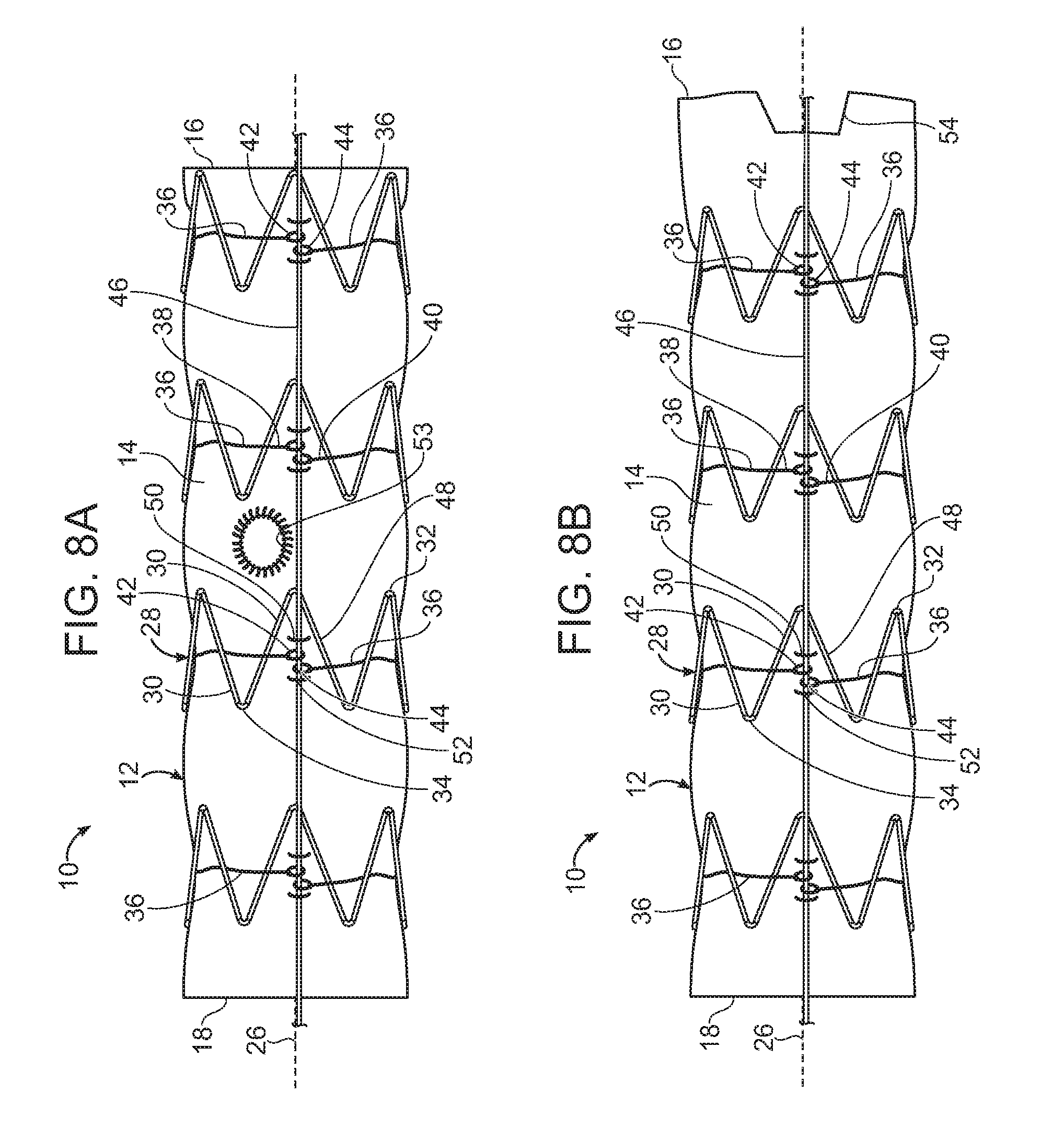
[0052] FIG. 8A is a side view of another embodiment of a stent graft delivery system of the invention, wherein the stent graft includes a fenestration.
[0053] FIG. 8B is a side view of yet another embodiment of a stent graft delivery system of the invention, wherein the proximal open end includes a scalloped edge.
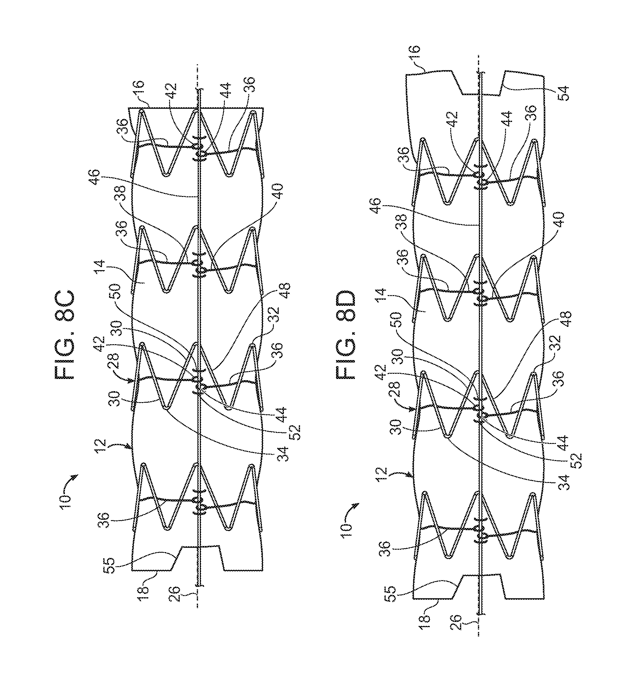
[0054] FIG. 8C is a side view of a further embodiment of a stent graft delivery system of the invention, wherein the distal open end includes a scalloped edge.
[0055] FIG. 8D is a side view of a further embodiment of a stent graft delivery system of the invention, wherein both the proximal and distal open ends include a scalloped edge.
[0056] FIG. 9 is an exploded side view of one embodiment of a stent graft delivery system of the invention.
[0057] FIG. 10A is a side view of the stent graft delivery system shown in FIG. 9, but in assembled form and, wherein the introducer sheath, containing a stent graft of the stent graft delivery system of the invention, has been delivered to an arterial aneurysm of a patient.
[0058] FIG. 10B is a side view of the stent graft delivery system of FIG. 10A, following proximal retraction of the introducer sheath along the stent graft delivery device, to thereby expose the stent graft, which is held in a radially constricted position by a wire of the stent graft delivery system.
[0059] FIG. 10C is a side view of the stent graft delivery system shown in FIGS. 10A and 10B, following partial retraction of the wire from ligatures that, when linked by the wire, holds the stent graft in a partially radially constricted position, while the remainder of the stent graft is in a radially expanded position.
[0060] FIG. 10D is a side view of the graft prosthesis delivery system shown in FIGS. 10A-10C, following full retraction of the wire from the stent graft, whereby the stent graft is in a radially expanded position along its entire length.
[0061] FIG. 10E is a side view of the stent graft delivery system shown in FIGS. 10A through 10D, following retraction of the remainder of the stent graft delivery system not implanted at the aneurysm, whereby implantation of the stent graft at the aneurysm of the patient is complete.
DETAILED DESCRIPTION
[0062] A description of example embodiments follows.
[0063] The invention is generally directed to a stent graft and a delivery system that includes a stent graft and a plurality of wires extending through the lumen of the stent graft and on each lateral side of a fenestration in the stent graft. The invention also is directed to a method of use of the stent graft and delivery system of the invention. The stent graft delivery system and method of its us treat aortic vascular damage, such as vascular damage associated with an aortic aneurysms, including in regions of the aorta having arterial branches that supply blood to vital organs and tissues, such as thoracic aortic aneurysms, abdominal aortic aneurysms, thoracoabdominal aortic aneurysms, including juxtarenal aortic aneurysms and short-neck abdominal aortic aneurysms.
[0064] When reference is made herein to a prosthesis, also referred to herein as "stent graft," "stent graft," or "vascular prosthesis," to be delivered, or implanted in a patient, the word "proximal" means that portion of the prosthesis or component of the prosthesis that is relatively close to the heart of the patient and "distal" means that portion of the prosthesis or component of the prosthesis that is relatively far from the heart of the patient.
[0065] When, however, reference is made to a delivery system or a component of a delivery system employed to deliver, or implant, a prosthesis, the word, "proximal," as employed herein, means closer to the clinician using the delivery system. When reference is made to a delivery system or a component of a delivery system, "distal," as that term is employed herein, means, further away from the clinician using the delivery system.
[0066] For clarity, the word "proximate" means "close to," as opposed to the meanings ascribed to "proximal" or "distal" described above with respect to either the prosthesis or a delivery system.
[0067] One embodiment of a stent graft delivery system of the invention is shown in FIG. 1A through 1F. As shown therein, stent graft delivery system 10 includes stent graft 12 of the invention. Stent graft 12 includes luminal graft component 14 having proximal open end 16, distal open end 18, and outside surface 20. Inside surface 22 defines a lumen about longitudinal axis 26. Luminal graft component 14 is fabricated of a suitable material, such as is known in the art. Examples of suitable materials include expanded polytetrafluoroethylene (ePTFE) and polyethylene terephthalate (PET), such as woven polyester.
[0068] Stents 28 of stent graft 12 are distributed radially about luminal graft component 14 and longitudinally along luminal graft component 14. Stents 28 include struts 30 that are joined at either end to defined proximal apices 32 and distal apices 34. Stents 28 are fabricated of a suitable material, such as is known in the art. In one embodiment, stents 28 are fabricated of a material that causes stents to radially self-expand upon release from radial constraint. Examples of suitable materials of radial self-expanding stents include a shape memory alloy, such as Nitinol. Examples of stents not formed of a shape memory alloy include those formed of stainless steel. In embodiments of the invention that do not employ a shape memory alloy, or are otherwise not radially self-expanding, a balloon catheter, for example, can be employed to radially expand stents that have been released from radial constriction, as is known in the art. Stents 28 can also include a radiopaque component, as is known in the art, such as at least one radiopacifier selected from the group consisting of barium sulfate, bismuth, tungsten, platinum-iridium and tantalum-tungsten.
[0069] Ligatures 36 extend about luminal graft component 14 and include ends 38,40. Ligatures 36 are formed of a suitable material, such as is known in the art. Examples of suitable materials of ligatures 36 include polyester, and nylon. As shown in FIG. 1A, ends of ligatures 36 include ligature loops 42,44. Ligature loops 42,44 are linked, such as by wire 46, as shown in FIG. 1A, to constrict the diameter of stent graft 12. As represented in FIG. 1A, ligatures 36 extend between stents 28 and luminal graft material 14, and traverse struts of stents 28, where ligatures 36 extend between stents 28 and luminal graft material 14. On either immediate lateral side of wire 46, ligatures 36 traverse struts 30 by passing over a radially outwardly-facing portion 48 of struts 30. Anchor loops 50,52 are distributed longitudinally on either side of the portion of wire 46 and ligature loops 42,44 of ligatures 36 and, consequently, span ligature loops 42,44 to stabilize wire 46, at least in part, from lateral migration of wire 46 about the periphery of stent graft 12. Ligatures 36 are formed of a suitable material, such as is known in the art. Examples of suitable materials of ligatures 36 include, for example, stainless steel or a shape-memory alloy, such as Nitinol. Likewise, anchor loops 50,52 are formed of a suitable material, such as a material suitable for fabrication of ligatures 36. It is to be understood that, in certain other embodiments, anchor loops 50,52 are not present, such as in embodiments where ligatures 36 are stabilized at stent graft 12 by, for example, being threaded between luminal graft component 14 and struts 30, thereby substantially preventing lateral migration of wire 46 when wire 46 is linking end 38,40 of ligatures 36.
[0070] Returning to FIG. 1A, wire 46 extends through loops 42,44 of ligatures, thereby linking ends 38,40 of ligatures 36 and maintaining stent graft 12 in a radially constricted position. It is to be understood that, when stents 28 are formed of a shape-memory metal alloy, such as Nitinol, then ligatures 36 hold stents 28 in a radially-constricted position, wherein radially self-expanding stents 28 exert a radially outward force against ligatures 36. It is also to be understood that, in alternative embodiments, ligatures 36 can traverse struts 30 between struts 30 and luminal graft component 14, or about radially outwardly-facing portion 48 of struts 30, in different arrangements than that shown in FIG. 1A. Further, it is to be understood that ligatures 36 can pass through the fabric of luminal graft component 14 into lumen 24 in various embodiments, such as in an embodiment wherein wire 46 extends through lumen 24 and against the inside surface of luminal graft component 14, as opposed to outside surface 20 of luminal graft component 14. Also, alternatively, in certain embodiments (not shown), stents 28 can be secured to luminal graft component 14 at inside surface 22 of luminal graft component 14, in which case wire 46 would, in one possible embodiment, extend within lumen 24, and ligatures 36 would traverse struts 30 between struts 30 and the inside surface of luminal graft component 14. Other arrangements between wire 46, ligatures 36 and stents 28 are also possible.
[0071] FIG. 1B is an end view of stent graft 12, as shown in FIG. 1A, taken along line 1B-1B. As can be seen in FIG. 1B, constricted open stent graft 12 has an inside diameter of D'. FIG. 1C is a side view of the stent and luminal graft component at proximal open end 16 of stent graft 12 shown in FIG. 1A, as viewed from line 1C-1C of FIG. 1B. Likewise FIGS. 1D, 1E, and 1F, show side views of the most proximal stent of stent graft 12, shown in the end view of FIG. 1B, taken along lines 1D-1D, 1E-1E and 1F-1F, respectively. Collectively, FIGS. 1A-1F show ligatures 36 extending about the perimeter of stent graft 12 and between struts 30 and luminal graft component 14, except for struts 30 on either lateral side of wire 46, where ligatures 36 pass over an outwardly-facing portion 48 of struts 30.
[0072] FIG. 2A is a side view of stent graft 12 shown in FIG. 1A, but following retraction of wire 46 from anchor loops 50,52 and loops 42,44 of ligatures 36, thereby allowing radial expansion of stents 28 from the constricted position, shown in FIGS. 1A-1F, to an expanded position, shown in FIG. 2A. Radial expansion of stents 28, such as by expansion of radially self-expanding stents 28 fabricated of, for example, Nitinol, causes ends 38,40 and, specifically, loops 42,44 of ligatures 36 to separate from each other and from anchor loops 50,52 longitudinally spanning wire loops 42,44 where wire 46 had previously linked loops 42,44 between anchor loops 50,52. FIG. 2B is an end view of stent graft 12 of FIG. 2A, taken along line 2B-2B, showing an expanded internal diameter D'' following release of stent graft 12 from the radially constricted position represented in FIGS. 1A-1F. FIGS. 2C, 2D, 2E and 2F show side views of the most proximal stent and the luminal graft component at proximal open end 16 represented in FIG. 2B, taken along lines 2C-2C, 2D-2D, 2E-2E, and 2F-2F respectively.
[0073] FIG. 3A is a side view of another embodiment of the stent graft delivery system of the invention. As shown therein, stent graft delivery system 60 additionally supports ligatures 36 by ligature sutures 62,64 at stent graft 12 between each loop 42,44 and struts 30 they traverse on either side of wire 46. The arrangement of ligature sutures 62,64 between loops 42,44 and respective struts 30 traversed by ligatures 36 stabilizes linkage of loops 42,44 by wire 46. It is to be understood that, in still another embodiment, ligature sutures 62,64 can be employed in the alternative to anchor loops 50,52 to thereby stabilize loops 42,44 when linked by wire 46. FIG. 3B is an end view of proximal open end 16 of stent graft 12 shown in FIG. 3A, taken along line 3B-3B, and showing inside diameter D' of most radially constricted stent graft 12. FIGS. 3C, 3D, 3E and 3F, show side views of the most proximal stent 28 and luminal graft component at proximal open end 16 shown in cross-section in FIG. 3B, taken along lines 3C-3C, 3D-3D, 3E-3E, and 3F-3F, respectively.
[0074] FIG. 4A is a side view of stent graft delivery system 60 shown in FIG. 3A, following retraction and withdrawal of wire 46 from anchor loops 50,52 and linkage of loops 42,44. As can be seen therein, radial expansion of stents 28 from a radially constricted position to a radially expanded position causes loops 42,44 to laterally separate from each other and, as shown in FIG. 4A, to retract from the ligature sutures 62,64, respectively. FIG. 4B is an end view of the stent graft in a radially expanded position, as shown in FIG. 4A, taken along line 4B-4B, showing the expanded inside diameter D'' following radial expansion of stent 28 at that section. FIGS. 4C, 4D, 4E, and 4F, show side views of the most proximal stent 28 and luminal graft component 14 at the most proximal stent 28 shown in cross-section in FIG. 4B, taken along lines 4C-4C, 4D-4D, 4E-4E, and 4F-4F, respectively.
[0075] FIG. 5A is a side view of yet another embodiment of a stent graft delivery system of the invention. As shown in FIG. 5A, stent graft delivery system 70 includes ligatures 72 at each stent 74 of stent graft 94. Ligatures 72 include two component parts 76,78, each of which is secured at separate struts 80,82 of respective stent 74. Ligatures 72 include loops 84,86 at each end that are aligned by wire 92, which passes through them, thereby maintaining stent graft 94 in a constricted position. Ligature parts 76,78 are stabilized by anchor loops 100,102 longitudinally spanning loops 84,86 when wire 92 is threaded through loops 84,86, thereby radially constricting stents 74. Although not shown, it is to be understood, that ligature sutures can, optionally, also be employed, as described with respect to FIGS. 1A and 3A. FIG. 5B is an end view of the stent graft delivery system 70 shown in FIG. 5A, taken along line 5B-5B, showing an internal diameter D' of stent graft 94 in a radially constricted position. FIGS. 5C, 5D, 5E, 5F, show side views of the most proximal stent 74 and the portion of the luminal graft component at the most proximal stent 74, shown in FIG. 5B taken along lines 5C-5C, 5D-5D, 5E-5E and 5F-5F, respectively.
[0076] FIG. 6A is a side view of stent graft 94 shown in FIG. 5A, following retraction of wire 92 from anchor loops 100,102 and loops 82,84 of ligatures 72, thereby allowing stent graft 94 to radially expand from the radially constricted position, shown in FIGS. 5A-5F, to a radially expanded position, shown in FIG. 6A. As can be seen in FIG. 6A, loops 84,86 laterally separate from each other, and from anchor loops 100,102 upon radial expansion of stent graft 94 from the radially constricted state to the expanded state. FIG. 6B is an end view of stent graft 94 shown in FIG. 6B, taken along line 6B-6B, showing a radially expanded internal diameter D'' of stent graft 94. FIGS. 6C, 6D, 6E, and 6F, show side views of the most proximal stent 74 and the portion of luminal graft component 95 most proximate to the most proximal stent 74, shown in FIG. 6B, taken along lines 6C-6C, 6D-6D, 6E-6E, and 6F-6F, respectively.
[0077] In another embodiment, circular ligatures 160 extend about the periphery of stent graft 12 to form distally opposed ends 162,164 of circular ligatures 160 that are linked by wire 46. Wire 46 is stabilized by anchor loops 50,52 at the stent graft as shown in FIGS. 7A, 7F.
[0078] As shown in FIGS. 8A through 8D, stent graft 10 can include at least one proximal fenestration 53 (FIG. 8A), a scalloped proximal open end 54 (FIG. 8B), a scalloped distal open end 55 (FIG. 8C) and a scalloped proximal and distal open ends 54,55, respectively (FIG. 8D). Although not shown, stent graft 10 can include at least one fenestration in combination with at least one of a scalloped proximal open end and a scalloped distal open end. In additional embodiments, the stent grafts of the invention can include a bare stent at at least one of the proximal open end and distal open end that, optionally, include barbs at respective proximal or distal apices (not shown).
[0079] FIG. 9 is an exploded side view of another embodiment of the stent graft delivery system of the invention. As shown therein, stent graft delivery system 110 includes guidewire catheter 112 having proximal end 114 and distal end 116. Proximal handle 118 is fixed to proximal end 114 of guidewire catheter 112. Nose cone 120 is fixed to distal end 116 of guidewire catheter 112. Wire 122 includes proximal end 124 and distal end 126. Wire 122 can be fabricated of a suitable material, such as is known in the art, including, for example, Nitinol or some other shape memory alloy. Wire 122 is sufficiently flexible not to injure the patient during advancement to an aortic aneurysm of a patient. Wire handle 128 is fixed at proximal end 124 of wire 122. Introducer sheath 130 includes proximal end 132 and distal end 134, and distal handle 136 is fixed to proximal end 132 of introducer sheath 130. Stent graft 138 includes proximal end 140, distal end 142, luminal graft component 144, stents 146 distributed along luminal graft component 144, and ligatures 148, arranged and configured as discussed above.
[0080] FIG. 10A is an assembled side view of stent graft delivery system 110 shown in FIG. 9, wherein stent graft 138 has been loaded within distal end 134 of introducer sheath 130, and radially constricted, at least in part, by wire 122 threaded through loops 150 at ends of ligatures 148, as discussed above, and through stabilizing anchor loops 153. In an embodiment, stent graft 138 includes fenestration 139. In a method of the invention, stent graft delivery system 110 is advanced to arterial aneurysm 152 of a patient. In one embodiment, shown in FIG. 10A, introducer sheath 130 is advanced to aneurysm site 152 to thereby place stent graft 138 at arterial aneurysm 152. As can be seen in FIG. 10B, distal handle 136 is retracted in a proximal direction indicated by arrow 160 toward proximal handle 118, thereby retracting introducer sheath 130 from stent graft 138 at aneurysm 152. As can be seen in FIG. 10B, despite retraction of introducer sheath 130, stent graft 138 is maintained in a radially constricted position by wire 122 extending through ligature loops 150 of ligatures 148 traversing struts of stents 146 distributed longitudinally along stent graft 138. It is to be understood, however, that in alternative embodiments, stent graft delivery system 110 can be advanced within an artery to a position distal to arterial aneurysm 152, wherein stent graft 138 is directed to arterial aneurysm 152 by advancement of proximal handle 118 and wire handle 128 in a distal direction indicated by arrow 162 toward distal handle 136 to thereby direct radially constricted stent graft 118 from introducer sheath 130 to arterial aneurysm 152.
[0081] Following direction of stent graft to a position that spans aneurysm 152, and at least partial rotational and axial alignment of stent graft at aneurysm 152, wire 122 is partially retracted from loops 150 of ligatures and from anchor loops 153. Proximal retraction of wire handle 128 toward proximal handle 118, in the direction indicated by arrow 160, as can be seen in FIG. 10C. Continued retraction of wire 122 withdraws wire 122 from all of suture loops 150 of ligatures 148 and anchor loops 153, thereby enabling stent graft 138 to fully expand from its radially constricted state, shown in FIG. 10B, to a radially expanded state, shown in FIG. 10D. In an embodiment, stent graft 138 is positioned so that fenestration 139 is properly aligned with arterial branch 154 for subsequent placement of branch prosthesis 156 through fenestration 139 to arterial branch 154. Thereafter, stent graft 138 is fully implanted within aneurysm, and the remainder of stent graft delivery device 110 is retracted from stent graft 138 and the patient, as shown in FIG. 10E, thereby completing treatment of aneurysm site 152 of the patient by the method of the invention.
[0082] Vascular prostheses implanted by the stent graft systems and methods of the invention can be implanted, for example, by transfemoral access. Additional branch prostheses that are directed into the vascular prostheses of the invention can be implanted, for example, by supraaortic vessel access (e.g., through the brachial artery), or by transfemoral access, or access from some other branch or branches of major blood vessels, including peripheral blood vessels.
[0083] The teachings of all patents, published applications and references cited herein are incorporated by reference in their entirety. The relevant teachings of all patents, published applications and references cited herein are incorporated by reference in their entirety. The relevant teachings of U.S. Pat. Nos. 8,292,943; 7,763,063; 8,308,790; 8,070,790; 8,740,963; 8,007,605; 9,320,631; 8,062,349; 9,198,786; 8,062,345; 9,561,124; 9,173,755; 8,449,595; 8,636,788; 9,333,104; 9,408,734; 9,408,735; 8,500,792; 9,220,617; 9,364,314; 9,101,506; 8,998,970; 9,554,929; 9,439,751; 9,592,112; 9,655,712, 9,827,123, 9,877,857, 9,907,686; U.S. patent application Ser. Nos. 14/575,673; 15/166,818; 15/167,055; 14/272,818; 14/861,479; 15/478,424; 15/478,737; 15/587,664; 15/604,032; 15/672,404; 15/816,772; 15/839,272; 15/417,467; PCT/US2017/025844; PCT/US2017/025849; PCT/US2017/025912; PCT/US2017/034223 and PCT/US2017/046062, are also incorporated by reference in their entirety.
[0084] The relevant teachings of the "Delivery System For Radially Constricting a Stent Graft and Method of Use," by Eduardo Alejandro Garcia, Attorney Docket No.: 4221.1043-001, filed on Feb. 23, 2018; "System and Method to Radially Constrict Stent Graft," by Samuel Arbefeuille, Attorney Docket No.: 4221.1044-001, filed on Feb. 23, 2018; "Delivery System and Method to Radially Constrict a Stent Graft," by Timothy Lostetter, Attorney Docket No.: 4221.1046-001, filed on Feb. 23, 2018; "Vascular Prosthesis with Moveable Fenestration and Method of Use," by Samuel Arbefeuille, Attorney Docket No.: 4221.1047-001, filed on Feb. 23, 2018; "Stent Graft Delivery System with Constricted Sheath and Method of Use," by Timothy Lostetter, Attorney Docket No.: 4221.1048-001, filed on Feb. 23, 2018; "Stent Graft with Fenestration Lock and Methods of Use," by Timothy Lostetter, Attorney Docket No.: 4221.1049-001, filed on Feb. 23, 2018; "Vascular Prosthesis with Crimped Adapter and Methods of Use," by Samuel Arbefeuille, Attorney Docket No.: 4221.1052-001, filed on Feb. 23, 2018; "Radially Adjustable Stent Graft Delivery System and Method of Use," by Samuel Arbefeuille, Eduardo Alejandro Garcia and Scott L. Rush, Attorney Docket No.: 4221.1053-001, filed on Feb. 23, 2018; "Vascular Prosthesis with Fenestration Ring and Methods of Use," by Timothy Lostetter, Attorney Docket No.: 4221.1054-001, filed on Feb. 23, 2018; "Distal Torque Component, Delivery System and Method of Using Same," by Samuel Arbefeuille, Attorney Docket No.: 4221.1055-001, filed on Feb. 23, 2018, are also incorporated by reference in their entirety.
[0085] While example embodiments have been particularly shown and described, it will be understood by those skilled in the art that various changes in form and details may be made therein without departing from the scope of the embodiments encompassed by the appended claims.
* * * * *
D00000
D00001
D00002
D00003
D00004
D00005
D00006
D00007
D00008
D00009
D00010
XML
uspto.report is an independent third-party trademark research tool that is not affiliated, endorsed, or sponsored by the United States Patent and Trademark Office (USPTO) or any other governmental organization. The information provided by uspto.report is based on publicly available data at the time of writing and is intended for informational purposes only.
While we strive to provide accurate and up-to-date information, we do not guarantee the accuracy, completeness, reliability, or suitability of the information displayed on this site. The use of this site is at your own risk. Any reliance you place on such information is therefore strictly at your own risk.
All official trademark data, including owner information, should be verified by visiting the official USPTO website at www.uspto.gov. This site is not intended to replace professional legal advice and should not be used as a substitute for consulting with a legal professional who is knowledgeable about trademark law.