Monopolar Return Electrode Grasper With Return Electrode Monitoring
BEGG; NIKOLAI D.
U.S. patent application number 15/908890 was filed with the patent office on 2019-09-05 for monopolar return electrode grasper with return electrode monitoring. The applicant listed for this patent is COVIDIEN LP. Invention is credited to NIKOLAI D. BEGG.
| Application Number | 20190269451 15/908890 |
| Document ID | / |
| Family ID | 65635550 |
| Filed Date | 2019-09-05 |


| United States Patent Application | 20190269451 |
| Kind Code | A1 |
| BEGG; NIKOLAI D. | September 5, 2019 |
MONOPOLAR RETURN ELECTRODE GRASPER WITH RETURN ELECTRODE MONITORING
Abstract
An electrosurgical system includes a generator, a delivery device, a return device, and a return electrode monitor (REM). The delivery device is in electrical communication with the generator and has a delivery electrode configured to deliver electrosurgical energy to tissue. The return device has a first jaw member including a first return electrode and a second jaw member including a second return electrode. The first and second jaw members are configured to capture tissue between the first and second return electrodes. The REM is disposed within the generator and is in electrical communication with the first and second return electrodes to return electrosurgical energy delivered to tissue to the generator. The REM is configured to determine a size of a return contact area of the first and second return electrodes with tissue to prevent delivery of electrosurgical energy from the generator to tissue when the size of the return contact are is below a threshold size.
| Inventors: | BEGG; NIKOLAI D.; (WAYLAND, MA) | ||||||||||
| Applicant: |
|
||||||||||
|---|---|---|---|---|---|---|---|---|---|---|---|
| Family ID: | 65635550 | ||||||||||
| Appl. No.: | 15/908890 | ||||||||||
| Filed: | March 1, 2018 |
| Current U.S. Class: | 1/1 |
| Current CPC Class: | A61B 18/16 20130101; A61B 18/1233 20130101; A61B 2018/1253 20130101; A61B 2018/165 20130101; A61B 18/1206 20130101; A61B 2018/126 20130101; A61B 2018/00875 20130101; A61B 18/14 20130101 |
| International Class: | A61B 18/12 20060101 A61B018/12; A61B 18/14 20060101 A61B018/14 |
Claims
1. An electrosurgical system, comprising: a generator; a delivery device in electrical communication with the generator, the delivery device having a delivery electrode configured to deliver electrosurgical energy from the generator to tissue; a return device having a first jaw member and a second jaw member, the first jaw member including a first return electrode and the second jaw member including a second return electrode, the first and second jaw members configured to capture tissue between the first and second return electrodes; and a return electrode monitor in electrical communication with each of the first and second return electrodes, the return electrode monitor disposed within the generator and in electrical communication with the first and second return electrodes to return electrosurgical energy delivered to tissue to the generator, the return electrode monitor configured to determine a size of a return contact area of the first and second return electrodes with tissue and to prevent delivery of electrosurgical energy from the generator to tissue when the size of the return contact area is below a threshold size.
2. The electrosurgical system according to claim 1, wherein the return electrode monitor is configured to monitor an impedance between portions of the return device to determine the size of the return contact area, the return electrode monitor configured to prevent delivery of electrosurgical energy from the generator when the impedance is greater than an impedance threshold.
3. The electrosurgical system according to claim 2, wherein the return electrode monitor has a first return post and a second return post, the impedance being determined by a circuit extending from the first return post, extending to the return device, through tissue, and back to the second return post.
4. The electrosurgical system according to claim 3, wherein the first return electrode is connected to the first return post via a first return path and the second return electrode is connected to the second return post via a second return path.
5. The electrosurgical system according to claim 3, wherein the first and second return electrodes are both connected to the first return post via a first return path.
6. The electrosurgical system according to claim 1, wherein the return device includes an activation electrode positioned on the second jaw member proximal of the second return electrode.
7. The electrosurgical system according to claim 6, wherein the return electrode monitor is configured to prevent delivery of electrosurgical energy from the generator to tissue unless tissue is in contact with the activation electrode and at least one of the first return electrode or the second return electrode.
8. The electrosurgical system according to claim 6, wherein the first and second return electrodes are connected to a first return post of the return electrode monitor via a first return path and the activation electrode is connected to a second return post of the return electrode monitor via a second return path.
9. The electrosurgical system according to claim 8, wherein the return electrode monitor is configured to measure an impedance between the first and second return electrodes and the activation electrode to determine when tissue is in contact with the activation electrode.
10. An electrosurgical system, comprising: a generator; a delivery device in electrical communication with the generator, the delivery device having a delivery electrode configured to deliver electrosurgical energy from the generator to tissue; a return device having a first jaw member and a second jaw member, the first jaw member including a first return electrode and the second jaw member including a second return electrode, the first and second jaw members configured to capture tissue between the first and second return electrodes; and a return electrode monitor in electrical communication with each of the first and second return electrodes, the return electrode monitor disposed within the generator and in electrical communication with the first and second return electrodes to return electrosurgical energy delivered to tissue to the generator, the return electrode monitor configured to monitor an impedance between portions of the return device and to prevent delivery of electrosurgical energy from the generator to tissue when the monitored impedance is greater than a predetermined threshold impedance.
11. The electrosurgical system according to claim 10, wherein the return electrode monitor is configured to measure an impedance between the first and second return electrodes and an activation electrode to determine when tissue is in contact with the activation electrode, the activation electrode positioned on the second jaw member proximal of the second return electrode.
12. The electrosurgical system according to claim 10, wherein the return electrode monitor is configured to measure an impedance between the first and second return electrodes.
13. A method of treating tissue, the method comprising: capturing a purchase of tissue between first and second jaw members of a return device, the first jaw member having a first return electrode and the second jaw member having a second return jaw member; determining a size of a return contact area of the purchase of tissue with a return electrode monitor of a generator; preventing delivery of electrosurgical energy from the generator, with the return electrode monitor, when the size of the return contact area is below a threshold size; and delivering electrosurgical energy from the generator to tissue with an active electrode of a delivery device when the size of the return contact area is greater than the threshold size.
14. The method according to claim 13, wherein determining the size of the return contact area includes measuring an impedance between the first and second return electrodes.
15. The method according to claim 14, wherein preventing delivery of electrosurgical energy from the generator occurs when the impedance between the first and second return electrodes is greater than an impedance threshold.
16. The method according to claim 15, further comprising determining the impedance threshold from at least one of the delivery device, the active electrode of the delivery device, or a type of tissue.
17. The method according to claim 13, wherein determining the size of the return contact area includes measuring an impedance between the first and second return electrodes and an activation electrode disposed on the second jaw member proximal of the second return electrode.
18. The method according to claim 13, wherein preventing delivery of electrosurgical energy from the generator includes providing visual indicia on the delivery device.
19. The method according to claim 13, further comprising selecting a monopolar mode of the delivery device.
20. The method according to claim 13, further comprising: releasing the purchase of tissue when the return contact area is below the threshold size; and capturing another purchase of tissue between the first and second jaw members.
Description
BACKGROUND
1. Technical Field
[0001] The present disclosure relates generally to electrosurgical instruments and, more particularly, to return electrodes for monopolar electrosurgical instruments.
2. Discussion of Related Art
[0002] Electrosurgical medical devices have become widely used by surgeons. Electrosurgical medical devices include various hand-held instruments, e.g., an electrosurgical pencil, which transfers radio-frequency (RF) electrical energy to a tissue site from an electrosurgical generator. Electrical current is returned to the current source via a return electrode pad positioned under a patient, or a smaller return electrode positioned in bodily contact, with or immediately adjacent to, the surgical site. The waveforms which result from the RF electrical current may be used to produce a variety of tissue effects, depending on the power applied, and the frequency used. These effects include tissue cutting, coagulation, cauterization, and/or sealing.
[0003] The effects of the electrosurgical medical devices are localized to tissue in contact with an active electrode of the electrosurgical medical device. To ensure similar effects are not experienced at the return electrode, a contact area of the return electrode with the body of a patient is maximized such that a ratio of the active electrode with tissue and the contact area of the return electrode is minimized. As this ratio increases, there is an increased likelihood that effects may be experienced at the return electrode.
SUMMARY
[0004] Accordingly, there is a need for devices that monitor the contact area of the return electrodes during a surgical procedure to reduce the likelihood of effects occurring at the return pad.
[0005] In an aspect of the present disclosure, an electrosurgical system includes a generator, a delivery device, a return device, and a return electrode monitor (REM). The delivery device is in electrical communication with the generator and has a delivery electrode configured to deliver electrosurgical energy to tissue. The return device has a first jaw member including a first return electrode and a second jaw member including a second return electrode. The first and second jaw members are configured to capture tissue between the first and second return electrodes. The REM is disposed within the generator and is in electrical communication with the first and second return electrodes to return electrosurgical energy delivered to tissue to the generator. The REM is configured to determine a size of a return contact area of the first and second return electrodes with tissue to prevent delivery of electrosurgical energy from the generator to tissue when the size of the return contact are is below a threshold size.
[0006] In aspects, the REM is configured to monitor an impedance between portion of the return device to determine the size of the return contact area. The REM may be configured to prevent delivery of electrosurgical energy from the generator when the impedance is greater than an impedance threshold. The REM has a first return post and a second return post. The impedance may be determined by a circuit extending from the first return post, extending to the return device, through tissue, and back to the second return post. The first return electrode may be connected to the first return post via a first return path and the second return electrode may be connected to the second return post via a second return path. Alternatively, the first and second return electrodes may both be connected to the first return post via the first return path.
[0007] In some embodiments, the return device includes an activation electrode positioned on the second jaw member proximal of the second return electrode. The REM may be configured to prevent delivery of electrosurgical energy from the generator to tissue unless tissue is in contact with the activation electrode and at least one of the first or second return electrodes. The first and second electrodes may be connected to a first return post of the REM via a first return path and the activation electrode may be connected to a second return post of the REM via a second return path. The REM may be configured to measure impedance between the first and second return electrodes and the activation electrode to determine when tissue is in contact with the activation electrode.
[0008] In another aspect of the present disclosure, a generator, a deliver device, a return device, and a REM. The delivery device is in electrical communication with the generator. The delivery device has a delivery electrode that is configured to deliver electrosurgical energy from the generator to tissue. The return device has a first jaw member and a second jaw member. The first jaw member includes a first return electrode and the second jaw member includes a second return electrode. The first and second jaw members are configured to capture tissue between the first and second return electrodes. The REM is in electrical communication with each of the first and second return electrodes. The REM is disposed within the generator and is in electrical communication with the first and second return electrodes to return electrosurgical energy deliver to tissue to the generator. The REM is configured to monitor impedance between portions of the return device and to prevent delivery of electrosurgical energy from the generator to tissue when the monitored impedance is greater than predetermined threshold impedance.
[0009] In aspects, the REM is configured to measure an impedance between the first and second return electrodes and an activation electrode to determine when tissue is in contact with the activation electrode. The activation electrode may be positioned on the second jaw member proximal of the second return electrode. Additionally or alternatively, the REM may be configured to measure an impedance between the first and second return electrodes.
[0010] In another aspect of the present disclosure, a method of treating tissue includes capturing a purchase of tissue, determining a size of a return contact area, preventing delivery of electrosurgical energy from a generator when the size of the return contact area is below a threshold size, and delivering electrosurgical energy from the generator when the size of the return contact area is greater than the threshold size. Capturing the purchase of tissue includes capturing the purchase between first and second jaw members of a return device. The first jaw member has a first return electrode and the second jaw member has a second return jaw member. Determining the size of the return contact area includes determining the return contact area with a REM of the generator. The electrosurgical energy may be delivered to tissue with an active electrode of the delivery device.
[0011] In aspects, determining the size of the return contact area includes measuring an impedance between the first and second return electrodes. Preventing delivery of electrosurgical energy from the generator may occur when the impedance between the first and second return electrodes is greater than an impedance threshold. The method may include determining the impedance threshold from at least one of the delivery device, the active electrode of the delivery device, or a type of tissue.
[0012] In some aspects, determining the size of the return contact area includes measuring impedance between the first and second return electrodes and an activation electrode that is disposed on the second jaw member proximal of the second return electrode. Preventing delivery of electrosurgical energy from the generator may include providing visual indicia on the delivery device and/or locking out an activation control of the delivery device.
[0013] In certain aspects, the method may include selecting a monopolar mode of the delivery device. The method may include releasing the purchase of tissue when the return contact area is below the threshold size and capturing another purchase of tissue between the first and second jaw members.
[0014] Further, to the extent consistent, any of the aspects described herein may be used in conjunction with any or all of the other aspects described herein.
BRIEF DESCRIPTION OF THE DRAWINGS
[0015] Various aspects of the present disclosure are described hereinbelow with reference to the drawings, which are incorporated in and constitute a part of this specification, wherein:
[0016] FIG. 1 is a schematic view of an electrosurgical system including a generator with a remote electrode monitor and a return device provided in accordance with our present disclosure;
[0017] FIG. 2 is a schematic view of the return device of FIG. 1 with a first purchase of tissue between jaw members of the return device;
[0018] FIG. 3 is a schematic view of the return device of FIG. 1 with a second purchase of tissue between the jaw members of the return device;
[0019] FIG. 4 is a flow chart of a method of using an electrosurgical system in accordance with the present disclosure;
[0020] FIG. 5 is a schematic view of another electrosurgical system including a generator with a remote electrode monitor and a return device provided in accordance with our present disclosure;
[0021] FIG. 6 is a schematic view of the return device of FIG. 5 with a first purchase of tissue between jaw members of the return device;
[0022] FIG. 7 is a schematic view of the return device of FIG. 6 with a second purchase of tissue between the jaw members of the return device; and
[0023] FIG. 8 is a schematic view of a robotic surgical system provided in accordance with the present disclosure.
DETAILED DESCRIPTION
[0024] Embodiments of the present disclosure are now described in detail with reference to the drawings in which like reference numerals designate identical or corresponding elements in each of the several views. As used herein, the term "clinician" refers to a doctor, a nurse, or any other care provider and may include support personnel. Throughout this description, the term "proximal" refers to the portion of the device or component thereof that is closer to the clinician and the term "distal" refers to the portion of the device or component thereof that is farther from the clinician.
[0025] Referring now to FIG. 1, an exemplary electrosurgical system 1 is illustrated including a return device or grasper 40 provided in accordance with the present disclosure. The electrosurgical system 1 includes an electrosurgical generator 10, a delivery or monopolar device 20, and the grasper 40. The electrosurgical generator 10 is in electrical communication with the monopolar device 20 via a delivery path or conductor 12. The electrosurgical generator 10 includes a Return Electrode Monitor (REM) 30 that is in electrical communication with the grasper 40 via a first return path or conductor 14 and a second return path or conductor 18. The REM 30 is described in greater detail below.
[0026] The monopolar device 20 includes an active electrode 22 that is configured to deliver electrosurgical energy to tissue to produce a variety of effects, depending on the power of the electrosurgical energy applied and the frequency of electrosurgical energy used. These effects include surgical cutting, coagulation, cauterization, and/or sealing. The electrosurgical generator 10 may allow for the power and/or frequency of the electrosurgical energy to be manually adjusted or may automatically adjust the power and/or frequency based on a predetermined or selected desired effect. The monopolar device 20 may include a mode selection switch 24 which allows a clinician to select a desired effect during a surgical procedure. The monopolar device 20 may include an activation switch 26 that allows for selective activation of the active electrode 22 such that the active electrode 22 delivers electrosurgical energy to tissue. The active electrode 22 may have a variety of shapes including, but not limited to, a conical tip, a flat tip, a hook, a loop, and combinations thereof. When the active electrode 22 delivers electrosurgical energy to tissue, the active electrode 22 defines a delivery contact area with tissue which is the surface area of the active electrode 22 in contact with tissue. The monopolar device 20 may be an electrosurgical device having both a monopolar mode and a bipolar mode. For a detailed description of exemplary electrosurgical devices, reference may be made to U.S. Pat. No. 9,549,775, the entire contents of which are hereby incorporated by reference.
[0027] The grasper 40 includes a first arm 42 having a first jaw member 44 and a second arm 46 having a second jaw member 48. The first and second arms 42, 46 are pivotable about a pivot 41 such that the first and second jaw members 44, 48 are movable relative to one another such that tissue can be grasped therebetween. Grasper 40 may take other forms such as an endoscopic grasper having an elongated shaft extending from a handle with an end effector having first and second jaw members that are movable relative to one another. In some embodiments, one of the first or second jaw members may be fixed relative to a shaft or arm of the device.
[0028] The first jaw member 44 includes a first return electrode 45 and the second jaw member 48 includes a second return electrode 49. The first and second return electrodes 45, 49 are configured to grasp a purchase of tissue therebetween such that a return contact area is defined by portions of the first and second electrodes 45, 49 in contact with the tissue. Specifically, the first return contact area 1RA (FIG. 2) is defined by a surface area of the first electrode 45 in contact with tissue and the second return contact area 2RA (FIG. 2) is defined by a surface area of the second electrode 49 in contact with tissue. The return contact area is the sum of the first and second contact areas 1RA, 2RA.
[0029] The REM 30 is configured to monitor the return contact area of grasper 40. The REM 30 is in communication with the first return electrode 45 via the first return path 14 connected to a first return post 34 of the REM 30 and the second return electrode 48 via the second return path 18 connected to a second return post 38 of the REM 30. As shown, the first and second return paths 14, 18 are separated between the REM 30 and the first and second return electrodes 45, 49, respectively; however, the first and second return paths 14, 18 may be formed of a single cable with multiple conductors between the REM 30 and the grasper 40, i.e., with the first and second return paths 14, 18 separated from one another at the grasper 40, e.g., adjacent the first and second jaw members 44, 48.
[0030] The REM 30 is configured to determine the return contact area of the first and second electrodes 45, 49 by monitoring an impedance between the first and second return electrodes 45, 49. Specifically, the REM 30 monitors the impedance of a circuit formed from the first return post 34, through the first return path 14, through the first electrode 45, through a purchase of tissue between the first and second return electrodes 45, 49, through the second electrode 49, through the second return path 18, and to the second return post 38. The impedance between the first and second return electrodes 45, 49 is indicative of the return contact area. As a size of the return contact area is increased, the impedance between the first and second return electrodes 45, 49 decreases. As the size of the return contact area decreases, the impedance between the first and second return electrodes 45, 49 increases. The REM 30 is configured to continuously determine and monitor the size of the return contact area before and during a surgical procedure. During a surgical procedure, the REM 30 is configured to deactivate and/or prevent the delivery of electrosurgical energy to the active electrode 22 when a size of the return contact area is below a predetermined threshold. The predetermined threshold of the size of the return contact area is associated with an impedance threshold which can be monitored by the REM 30 such that when an impedance monitored by the REM 30 is greater than the impedance threshold, the REM 30 deactivates or disables the delivery of electrosurgical energy from the electrosurgical generator 10.
[0031] The impedance threshold may be based on a ratio of a size of the return contact area to a size of the delivery contact area. Specifically, as the ratio increases, the size of the return contact area increases relative to the size delivery contact area. The impedance threshold may be set at a value to ensure that the ratio is greater than a ratio limit. When the ratio is greater than the ratio limit, the size of the return contact area compared to the size of the delivery contact area is large enough to ensure that effects of electrosurgical energy delivery from the active electrode 22 are not experienced at the return electrodes, e.g., return electrodes 45, 49. In some embodiments, the ratio limit is in the range of about 10:1; however, the ratio limit may be greater or smaller than 10:1.
[0032] The impedance threshold may be determined during a surgical procedure or may be preset by the manufacturer. Additionally or alternatively, the impedance threshold may be specific to a type or shape of the active electrode 22. For example, the impedance threshold may be higher for a conical active electrode than an impedance threshold with a flat active electrode where the size of the delivery contact area may be greater. The impedance threshold may be set when the monopolar device 20 is connected to the generator 10 such that the monopolar device 20 is in electrical communication with the generator 10. Additionally or alternatively, the impedance threshold may be set when an active electrode, e.g., active electrode 22, is secured to the monopolar device 20. In addition, the impedance threshold may be set when an electrosurgical device having both monopolar and bipolar modes has the monopolar mode selected or activated.
[0033] With reference to FIG. 2, the grasper 40 is shown with a first purchase of tissue T grasped between the first and second jaw members 44, 48 such that each of the first and second return electrodes 45, 49 have a small return contact area with the tissue T. Specifically, the first return contact area 1RA is shown along the first return electrode 45 and the second return contact area 2RA is shown along the second return electrode 49. When the tissue T is grasped as shown in FIG. 2, the impedance .OMEGA. between the first and second return electrodes 45, 49 is high and likely greater than an impedance threshold .OMEGA..sub.T such that the REM 30 deactivates or prevents the generator 10 from supplying electrosurgical energy to a monopolar device, e.g., monopolar device 20 (FIG. 1).
[0034] With reference to FIG. 3, the grasper 40 is shown with a second purchase of tissue grasped between the first and second jaw members 44, 48 such that each of the first and second return electrodes 45, 49 have a large return contact area with the tissue T. Specifically, the first return contact area IRA' is shown along the first return electrode 45 and the second return contact area 2RA' is shown along the second return electrode 49. When the tissue T is grasped as shown in FIG. 3, the impedance .OMEGA. between the first and second return electrodes is low and likely lower than an impedance threshold .OMEGA..sub.T such that the REM 30 allows for activation of the generator 10 to supply electrosurgical energy to a monopolar device, e.g., monopolar device 20 (FIG. 1).
[0035] Referring to FIG. 4, a method 200 of delivering electrosurgical energy to tissue with reference to the electrosurgical system 1 of FIG. 1. Initially, the return or grasping device 40 is connected to the generator 10 such that the first and second electrodes 45, 49 are in electrical communication with the REM 30 of the generator 10 by separate return paths, e.g., first and second return paths 14, 18 (Step 210). The delivery or monopolar device 20 is also connected to the generator 10 such that the monopolar device 20 is in electrical communication with the generator 10 (Step 220).
[0036] An active electrode 22 is then secured to the monopolar device 20 (Step 222). In embodiments, the active electrode 22 is selected from a plurality of active electrodes 22 based on the desired effect the active electrode 22 and/or on the type of tissue to be treated. The active electrode 22 may also be non-removable from the monopolar device 20. In some embodiments, the monopolar device 20 is selected by the active electrode 22 fixed to the monopolar device 20.
[0037] When the active electrode 22 is secured to the monopolar device 20, a monopolar mode of the monopolar device 20 is selected or activated (Step 224). The monopolar device 20 may include a mode selection switch 24 that allows a clinician to switch between a monopolar mode and a bipolar mode. In some embodiments, the monopolar device 20 is always in a monopolar mode such that when the generator 10 is activated, the monopolar mode of the monopolar device 20 is activated.
[0038] When the monopolar device 20 and the grasping device 40 are both connected to the generator 10 with the monopolar mode selected on the monopolar device 20, the REM 30 of the generator 10 determines a threshold impedance .OMEGA..sub.T (Step 230). The threshold impedance .OMEGA..sub.T may be set by a clinician or automatically determined by the REM 30 based on the active electrode 22, the geometry of the first and second return electrodes 45, 49, the type of tissue to be effected, and/or the desired effect. The grasping device 40 is then used grasp a purchase of tissue between the first and second return electrodes 45, 49 (Step 240). When the purchase of tissue is grasped between the first and second return electrodes 45, 49, the REM 30 determines the impedance .OMEGA. between the first and second return electrodes 45, 49 (Step 250). As detailed above, the impedance .OMEGA. is indicative to the size of a return contact area of the first and second return electrodes 45, 49 with the purchase of tissue. The REM 30 compares the measured impedance .OMEGA. to the threshold impedance .OMEGA..sub.T (Step 260).
[0039] When the impedance .OMEGA. is less than the threshold impedance .OMEGA..sub.T, the active electrode 22 is enabled or capable of being activated (Step 270). The active electrode 22 may be activated by a clinician actuating the activation switch 26. The monopolar device 20 may provide visual indicia that the active electrode 22 is enabled, e.g., a green light may appear on the monopolar device 20. After the active electrode 22 is activated to effect tissue, the active electrode 22 is deactivated. The active electrode 22 can then be reactivated to effect tissue again, the tissue can be regrasped, or the surgical procedure may be complete.
[0040] When the impedance .OMEGA. is greater than the threshold impedance .OMEGA..sub.T, the REM 30 deactivates or prevents the active electrode 22 from being activated (Step 280). The monopolar device 20 may provide visual indicia that the active electrode 22 is disabled, e.g., a red light may appear on the monopolar device 20. Additionally or alternatively, the activation switch 26 may be locked out such that the activation switch 26 may not be actuated to provide tactile indicia that the active electrode 22 is disabled. When the active electrode 22 is disabled, the clinician may release and grasp another purchase of tissue with the grasping device 40 (Step 240) until the REM 30 measures a new impedance .OMEGA. that is less than the threshold impedance .OMEGA..sub.T (Step 250).
[0041] Referring now to FIG. 5, another exemplary electrosurgical system 101 is illustrated including a return device or grasper 140 provided in accordance with the present disclosure. Some elements of the electrosurgical system 101 are similar to elements of the electrosurgical system 1 detailed above and are represented with similar labels. As such, only the differences will be detailed herein for brevity.
[0042] The electrosurgical system includes an electrosurgical generator 10, a monopolar device 20, and the grasper 140. The electrosurgical generator 10 includes a Return Electrode Monitor (REM) 30 that is in electrical communication with the grasper 140 via a first return path or conductor 14 and a second return path or conductor 18.
[0043] The grasper 140 includes a first arm 142 having a first jaw member 144 and a second arm 146 having a second jaw member 148. The first and second arms 142, 146 are pivotable relative to one another about a pivot 141 such that the first and second jaw members 144, 148 are pivotable relative to one another. The first jaw member 144 includes a first return electrode 145. The second jaw member 148 includes a second return electrode 149 and an activation electrode 147. The activation electrode 147 is positioned proximal of the second return electrode 149 and is electrically isolated from the first and second return electrodes 145, 149.
[0044] The REM 30 is configured to determine that the return contact area of the first and second electrodes 145, 149 is sufficient to prevent effects from the active electrode 22 to be seen at the first return electrode 145, the second return electrode 149, and/or the activation electrode 147. The REM 30 utilizes the activation electrode 147 to determine when a return contact area of a purchase of tissue grasped between the first and second return electrodes 145, 149 is large enough such that a ratio of the return contact area to a delivery contact area is greater than a ratio limit, e.g., about 10:1.
[0045] The REM 30 determines the return contact area is sufficient by monitoring the impedance .OMEGA. between the first and second electrodes 145, 149 and the activation electrode 147. The first and second electrodes 145, 149 are in electrical communication with one another through the return path 14 which is connected to the first post 34 of the REM 30. The activation electrode 147 is connected to the second post 38 of the REM 30 by the second return path 18.
[0046] With reference to FIG. 6, when a purchase of tissue T is grasped between the first and second jaw members 144, 148 such that the tissue T does not reach the activation electrode 147, an impedance .OMEGA. between the activation electrode 147 and the first and second return electrodes 145, 149 is extremely large and may not be measurable, i.e., approaching infinity. In such situations, the impedance .OMEGA. is greater than an impedance threshold .OMEGA..sub.T such that the REM 30 deactivates or prevents the generator 10 from supplying electrosurgical energy to a monopolar device, e.g., monopolar device 20 (FIG. 5).
[0047] With reference to FIG. 7, when a purchase of tissue T is grasped between the first and second jaw members 144, 148 such that the tissue T reaches and is in contact with the activation electrode 147, an impedance .OMEGA. between the activation electrode 147 and the first and second return electrodes 145, 149 is significantly less than the impedance .OMEGA. measured when the activation electrode 147 is not contacted. When the REM 30 determines that the tissue T is in contact with the activation electrode 147, the REM 30 allows for activation of the generator 10 to supply electrosurgical energy to a monopolar device, e.g., monopolar device 20 (FIG. 5).
[0048] When the grasper 140 includes the activation electrode 147, the impedance threshold .OMEGA..sub.T for the system 101 can be higher than the impedance threshold .OMEGA..sub.T for the system 1 since the impedance .OMEGA. difference between non-contact with the activation electrode 147 and contact with the activation electrode 147 is significantly greater than when the return contact area is greater than a ratio limit as shown in FIG. 2.
[0049] A method of using the system 101 is substantially similar to the method 200 and will not be detailed herein for brevity.
[0050] The various embodiments disclosed herein may also be configured to work with robotic surgical systems and what is commonly referred to as "Telesurgery." Such systems employ various robotic elements to assist the surgeon and allow remote operation (or partial remote operation) of surgical instrumentation. Various robotic arms, gears, cams, pulleys, electric and mechanical motors, etc. may be employed for this purpose and may be designed with a robotic surgical system to assist the surgeon during the course of an operation or treatment. Such robotic systems may include remotely steerable systems, automatically flexible surgical systems, remotely flexible surgical systems, remotely articulating surgical systems, wireless surgical systems, modular or selectively configurable remotely operated surgical systems, etc.
[0051] The robotic surgical systems may be employed with one or more consoles that are next to the operating theater or located in a remote location. In this instance, one team of surgeons or nurses may prep the patient for surgery and configure the robotic surgical system with one or more of the instruments disclosed herein while another surgeon (or group of surgeons) remotely control the instruments via the robotic surgical system. As can be appreciated, a highly skilled surgeon may perform multiple operations in multiple locations without leaving his/her remote console which can be both economically advantageous and a benefit to the patient or a series of patients.
[0052] The robotic arms of the surgical system are typically coupled to a pair of master handles by a controller. The handles can be moved by the surgeon to produce a corresponding movement of the working ends of any type of surgical instrument (e.g., end effectors, graspers, knifes, scissors, etc.) which may complement the use of one or more of the embodiments described herein. The movement of the master handles may be scaled so that the working ends have a corresponding movement that is different, smaller or larger, than the movement performed by the operating hands of the surgeon. The scale factor or gearing ratio may be adjustable so that the operator can control the resolution of the working ends of the surgical instrument(s).
[0053] The master handles may include various sensors to provide feedback to the surgeon relating to various tissue parameters or conditions, e.g., tissue resistance due to manipulation, cutting or otherwise treating, pressure by the instrument onto the tissue, tissue temperature, tissue impedance, etc. As can be appreciated, such sensors provide the surgeon with enhanced tactile feedback simulating actual operating conditions. The master handles may also include a variety of different actuators for delicate tissue manipulation or treatment further enhancing the surgeon's ability to mimic actual operating conditions.
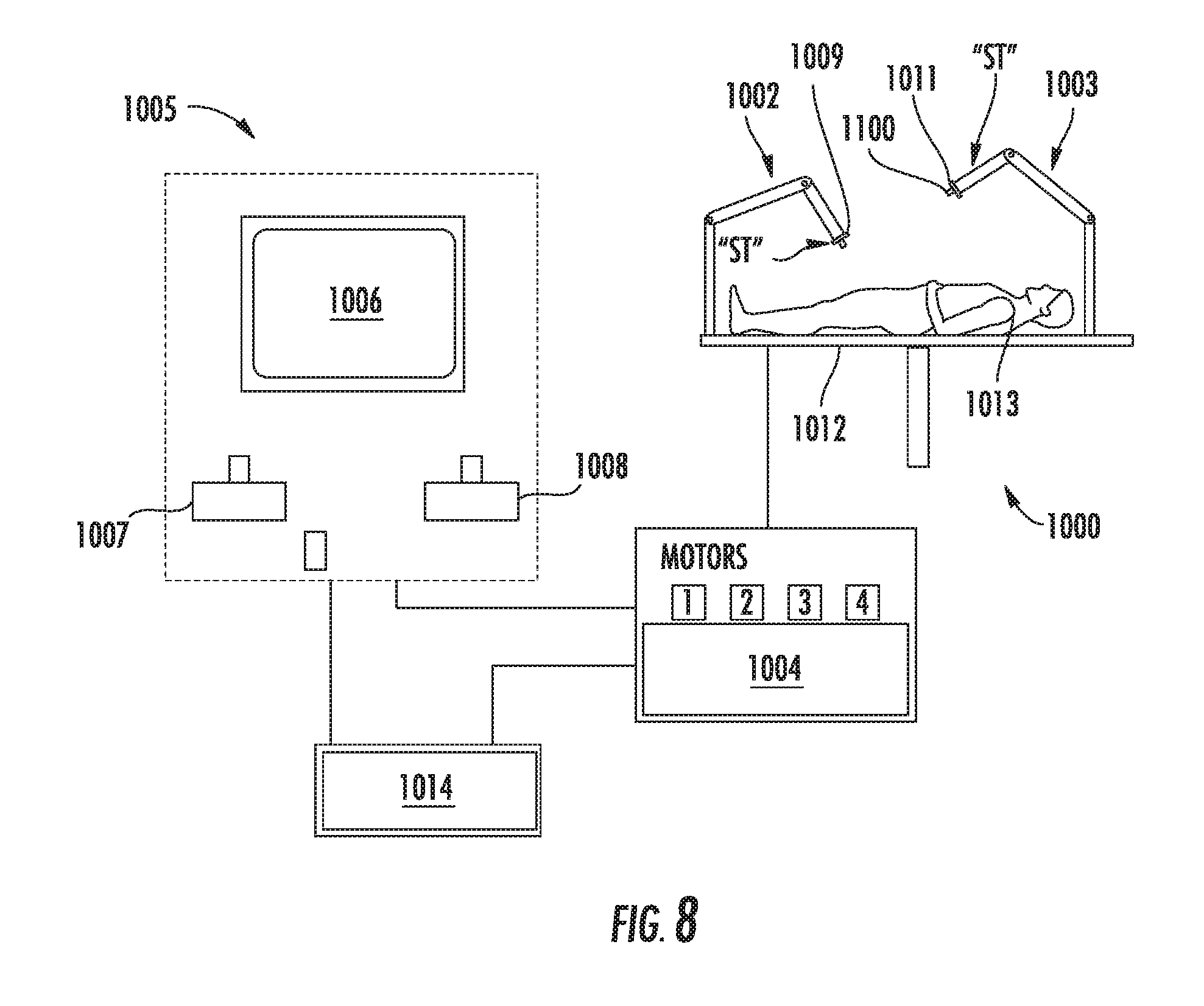
[0054] Turning to FIG. 8, a robotic surgical system configured for use in accordance with the present disclosure is shown generally identified by reference numeral 1000. Aspects and features of robotic surgical system 1000 not germane to the understanding of the present disclosure are omitted to avoid obscuring the aspects and features of the present disclosure in unnecessary detail.
[0055] Robotic surgical system 1000 generally includes a plurality of robot arms 1002, 1003; a control device 1004; and an operating console 1005 coupled with control device 1004. Operating console 1005 may include a display device 1006, which may be set up in particular to display three-dimensional images; and manual input devices 1007, 1008, by means of which a person, e.g., a surgeon, may be able to telemanipulate robot arms 1002, 1003 in a first operating mode. Robotic surgical system 1000 may be configured for use on a patient 1013 lying on a patient table 1012 to be treated in a minimally invasive manner. Robotic surgical system 1000 may further include a database 1014, in particular coupled to control device 1004, in which are stored, for example, pre-operative data from patient 1013 and/or anatomical atlases.
[0056] Each of the robot arms 1002, 1003 may include a plurality of members, which are connected through joints, and an attaching device 1009, 1011, to which may be attached, for example, a surgical tool "ST." One or more of the surgical tools "ST" may include a DLU, e.g., DLU 100, similar to those detailed above, thus providing such functionality on a robotic surgical system 1000.
[0057] Robot arms 1002, 1003 may be driven by electric drives, e.g., motors, connected to control device 1004. Control device 1004, e.g., a computer, may be configured to activate the motors, in particular by means of a computer program, in such a way that robot arms 1002, 1003, their attaching devices 1009, 1011, and, thus, the surgical tools "ST" execute a desired movement and/or function according to a corresponding input from manual input devices 1007, 1008, respectively. Control device 1004 may also be configured in such a way that it regulates the movement of robot arms 1002, 1003 and/or of the motors. The surgical tools "ST" may include optical-based sealing instruments configured to seal and/or cut tissue without a mechanical blade detailed above.
[0058] While several embodiments of the disclosure have been shown in the drawings, it is not intended that the disclosure be limited thereto, as it is intended that the disclosure be as broad in scope as the art will allow and that the specification be read likewise. Any combination of the above embodiments is also envisioned and is within the scope of the appended claims. Therefore, the above description should not be construed as limiting, but merely as exemplifications of particular embodiments. Those skilled in the art will envision other modifications within the scope of the claims appended hereto.
* * * * *
D00000
D00001
D00002
D00003
D00004
XML
uspto.report is an independent third-party trademark research tool that is not affiliated, endorsed, or sponsored by the United States Patent and Trademark Office (USPTO) or any other governmental organization. The information provided by uspto.report is based on publicly available data at the time of writing and is intended for informational purposes only.
While we strive to provide accurate and up-to-date information, we do not guarantee the accuracy, completeness, reliability, or suitability of the information displayed on this site. The use of this site is at your own risk. Any reliance you place on such information is therefore strictly at your own risk.
All official trademark data, including owner information, should be verified by visiting the official USPTO website at www.uspto.gov. This site is not intended to replace professional legal advice and should not be used as a substitute for consulting with a legal professional who is knowledgeable about trademark law.