RF-Transparent Case with Integral Clip
Christian; Patrick ; et al.
U.S. patent application number 15/910566 was filed with the patent office on 2019-09-05 for rf-transparent case with integral clip. This patent application is currently assigned to Samsonite IP Holdings S.ar.I.. The applicant listed for this patent is Samsonite IP Holdings S.ar.I.. Invention is credited to Ivan Chen, Patrick Christian, Bryan Lee Hynecek, Christopher William Ledesma, Alan Yu Tung Ng.
| Application Number | 20190269231 15/910566 |
| Document ID | / |
| Family ID | 67767506 |
| Filed Date | 2019-09-05 |


| United States Patent Application | 20190269231 |
| Kind Code | A1 |
| Christian; Patrick ; et al. | September 5, 2019 |
RF-Transparent Case with Integral Clip
Abstract
A case for a mobile device, including a first RF-transparent layer forming a pocket or recess for a mobile device, and a clip portion extending from a first wall of the pocket or recess. The clip portion extends away from a first wall of the pocket or recess, with the clip portion and the first wall forming a ring. The clip portion includes an external clip portion, an internal clip portion arranged inside the external clip portion, and a hinged gate. The internal clip portion is separate and distinct from the eternal clip portion. The hinged gate is rotatable around a hinge portion between a closed position in which the ring is closed, and an open position in which the ring is open. The first RF-transparent layer and the external and internal clip portions are formed from materials such that radio frequency ("RF") transmissions can be transmitted through them.
| Inventors: | Christian; Patrick; (Petaluma, CA) ; Ng; Alan Yu Tung; (San Francisco, CA) ; Hynecek; Bryan Lee; (Redwood City, CA) ; Chen; Ivan; (San Francisco, CA) ; Ledesma; Christopher William; (San Francisco, CA) | ||||||||||
| Applicant: |
|
||||||||||
|---|---|---|---|---|---|---|---|---|---|---|---|
| Assignee: | Samsonite IP Holdings
S.ar.I. Luxembourg LU |
||||||||||
| Family ID: | 67767506 | ||||||||||
| Appl. No.: | 15/910566 | ||||||||||
| Filed: | March 2, 2018 |
| Current U.S. Class: | 1/1 |
| Current CPC Class: | A45C 2011/002 20130101; A45F 2200/0516 20130101; A45F 2200/0508 20130101; A45C 11/00 20130101; A45F 5/00 20130101; A45C 2011/001 20130101; A45C 2011/003 20130101; A45F 2200/0525 20130101 |
| International Class: | A45F 5/00 20060101 A45F005/00; A45C 11/00 20060101 A45C011/00 |
Claims
1. A case for a mobile device, comprising: a first RF-transparent layer that forms a pocket or recess in which the mobile device can be arranged, the first layer being formed from a first material such that radio frequency ("RF") transmissions can be transmitted through the first layer; and a clip portion that extends from a first wall of the pocket or recess in a direction away from the pocket or recess, the clip portion and the first wall forming a ring, the clip portion comprising: an external clip portion formed from a second material such that RF transmissions can be transmitted through the external clip portion; an internal clip portion that is arranged inside the external clip portion, is formed from a third material such that RF transmissions can be transmitted through the internal clip portion, the internal clip portion being separate and distinct from the eternal clip portion; and a hinged gate that is rotatable around a hinge portion between a closed position in which the ring is closed, and an open position in which the ring is open; wherein the first, second, and third materials are the same, different, or a combination thereof.
2. The case for a mobile device according to claim 1; wherein the first layer forms the external clip portion.
3. The case for a mobile device according to claim 1; wherein the internal clip portion is permanently attached to the external clip portion.
4. The case for a mobile device according to claim 1; wherein the ring is rectangular in shape.
5. The case for a mobile device according to claim 1; wherein the first, second, and third materials are nonmetallic materials.
6. The case for a mobile device according to claim 1; wherein the hinged gate comprises at least one metal.
7. The case for a mobile device according to claim 6; wherein the case includes no metal or RF-blocking components or materials other than the hinged gate.
8. The case for a mobile device according to claim 1; wherein the case includes no metal or RF-blocking components or materials.
9. The case for a mobile device according to claim 1, further comprising: a second RF-transparent layer that is arranged inside the pocket or recess of the first layer, and which is formed from a fourth material such that RF transmissions can be transmitted through the second layer, the fourth material being different from the first material.
10. The case for a mobile device according to claim 9; wherein the second layer is permanently attached to the first layer.
11. The case for a mobile device according to claim 9; wherein the fourth material is a nonmetallic material.
12. The case for a mobile device according to claim 9; wherein the fourth material is a soft elastomeric material.
13. The case for a mobile device according to claim 12; wherein the soft elastomeric fourth material is selected from the group consisting of thermoplastic elastomers ("TPEs"), thermoplastic polyurethane ("TPU"), polyolefins, silicone, rubber, and combinations thereof.
14. The case for a mobile device according to claim 9; wherein each of the first, second, third, and fourth materials is translucent, transparent, or clear, so that one or more sides of the mobile device can be seen through the one or more respective sides of the case when the mobile device is arranged inside the case.
15. The case (1) for a mobile device according to claim 1; wherein the first material is a hard or rigid material.
16. The case for a mobile device according to claim 15; wherein the hard or rigid first material is selected from the group consisting of hardened plastic material, a rigid or semi-rigid plastic material, a rigid/hard rubber material, a polycarbonate material, a para-aramid material, wood, glass, quartz, thermosetting plastics with a hard durometer having shore 30D to shore 100D, polycarbonate, poly(methyl methacrylate) ("PMMA"), acrylonitrile butadiene styrene ("ABS"), PMMA, polyethylene terephthalate ("PET"), high durometer thermoplastic elastomers ("TPEs") and thermoplastic polyurethanes ("TPUs") having shore 30D to shore 100D, and any combination thereof.
17. The case for a mobile device according to claim 1; wherein the first layer forms: a rear side that forms at least part of a rear wall of the pocket or recess; a first side that extends from the rear side and forms at least part of the first wall of the pocket or recess; a second side opposite to the first side, the second side extending from the rear side and forming at least part of a second wall of the pocket or recess; a third side that extends from the rear side between the first and second sides, and which forms at least part of a third wall of the pocket or recess; and a fourth side opposite to the third side, the fourth side extending from the rear side between the first and second sides and forming at least part of a fourth wall of the pocket or recess.
18. The case for a mobile device according to claim 1; wherein a thickness of the internal clip portion in a radial direction of the ring is greater than a thickness of the external clip portion in the radial direction of the ring.
19. A case for a mobile device, comprising: a first layer that forms a pocket or recess in which the mobile device can be arranged, the first layer being formed from a first material; and a clip portion that extends from a first wall of the pocket or recess in a direction away from the pocket or recess, the clip portion and the first wall forming a ring, the clip portion comprising: an external clip portion formed from a second material; an internal clip portion that is arranged inside the external clip portion, is formed from a third material, and is separate and distinct from the eternal clip portion; and a hinged gate that is rotatable around a hinge portion between a closed position in which the ring is closed, and an open position in which the ring is open; wherein a thickness of the internal clip portion in a radial direction of the ring is greater than a thickness of the external clip portion in the radial direction of the ring.
20. The case for a mobile device according to claim 18; wherein the first layer forms the external clip portion.
Description
FIELD OF THE INVENTION
[0001] The present invention relates to a case for a mobile device. The case is made from a material that is transparent to radio frequencies ("RF") so that RF transmissions can be sent and received through the case material by the mobile device when arranged within the case. The case also has a clip that is integral with the case so that the case itself can be directly attached to an item worn by a user, such as a loop, belt, strap, ring, or the like.
[0002] Cases for mobile devices have been designed to provide at least some protection from impact events, such as when the device is dropped, hit, or otherwise struck. These cases are typically placed in a pocket or bag when being carried by a user. This can be a problem in an emergency as it can make it difficult, or even impossible, to access the mobile device.
[0003] Other cases for mobile devices have incorporated a loop on the case to which a clip, shackle, or the like--such as a carabiner--can be attached. The clip or shackle can then be attached to an item worn by a user. But this can be bulky and uncomfortable, as the clip or shackle is rotated at an angle with respect to the case when attached to the loop. In addition, the loop of the case and the clip or shackle are able to rub together during use, which creates wear on the loop, potentially resulting in failure of the loop and loss of the device.
[0004] Another case by Elecom incorporates a carabiner into the side of an aluminum bumper case. But this case must be attached to the mobile device with screws, making it difficult to take on and off. In addition, the bumper case is aluminum, likely to provide enough strength to the carabiner portion. But aluminum, like other metals, can block or interfere with RF transmissions, which may be why the case was designed as a bumper and not as a full case. In addition, aluminum provides little to no shock absorption.
SUMMARY OF THE INVENTION
[0005] As such, it is desirable to provide a new case for a mobile device which can provide shock/impact protection to a mobile device and be directly clipped to a user while still allowing for RF transmissions to and from the mobile device when arranged in the case.
[0006] According to the present invention there is therefore provided a case for a mobile device as described by way of example below and in the accompanying claims.
[0007] In one embodiment of the invention there is provided a case (1) for a mobile device, including a first RF-transparent layer (2) and a clip portion (30). The first RF-transparent layer (2) forms a pocket or recess (19) in which the mobile device can be arranged, and is formed from a first material such that radio frequency ("RF") transmissions can be transmitted through the first layer (2). The clip portion (30) extends from a first wall (7) of the pocket or recess (19) in a direction away from the pocket or recess (19), with the clip portion (30) and the first wall (7) forming a ring. The clip portion (30) includes an external clip portion (31), an internal clip portion (32), and a hinged gate (33). The external clip portion (31) is formed from a second material such that RF transmissions can be transmitted through the external clip portion (31). The internal clip portion (32) is arranged inside the external clip portion (31), and is formed from a third material such that RF transmissions can be transmitted through the internal clip portion (32), the internal clip portion (32) being separate and distinct from the eternal clip portion (31). The hinged gate (33) is rotatable around a hinge portion (34) between a closed position in which the ring is closed, and an open position in which the ring is open. The first, second, and third materials are the same, different, or a combination thereof.
[0008] In another embodiment, the first layer (2) forms the external clip portion (31).
[0009] In yet another embodiment, the internal clip portion (32) is permanently attached to the external clip portion (31).
[0010] In a further embodiment, the ring is rectangular in shape.
[0011] In yet a further embodiment, the first, second, and third materials are nonmetallic materials.
[0012] In another embodiment, the hinged gate (33) comprises at least one metal.
[0013] In yet another embodiment, the case (1) includes no metal or RF-blocking components or materials other than the hinged gate (33).
[0014] In a further embodiment, the case (1) includes no metal or RF-blocking components or materials.
[0015] In yet a further embodiment, the case (1) further includes a second RF-transparent layer (3) that is arranged inside the pocket or recess (19) of the first layer (2), and which is formed from a fourth material such that RF transmissions can be transmitted through the second layer (3), the fourth material being different from the first material.
[0016] In another embodiment, the second layer (3) is permanently attached to the first layer (2).
[0017] In yet another embodiment, the fourth material is a nonmetallic material.
[0018] In a further embodiment, the fourth material is a soft elastomeric material.
[0019] In yet a further embodiment, the soft elastomeric fourth material is selected from the group consisting of thermoplastic elastomers ("TPEs"), thermoplastic polyurethane ("TPU"), polyolefins, silicone, rubber, and combinations thereof.
[0020] In another embodiment, each of the first, second, third, and fourth materials is translucent, transparent, or clear, so that one or more sides of the mobile device can be seen through the one or more respective sides of the case (1) when the mobile device is arranged inside the case.
[0021] In yet another embodiment, the first material is a hard or rigid material.
[0022] In a further embodiment, the hard or rigid first material is selected from the group consisting of hardened plastic material, a rigid or semi-rigid plastic material, a rigid/hard rubber material, a polycarbonate material, a para-aramid material, wood, glass, quartz, thermosetting plastics with a hard durometer having shore 30D to shore 100D, polycarbonate, poly(methyl methacrylate) ("PMMA"), acrylonitrile butadiene styrene ("ABS"), PMMA, polyethylene terephthalate ("PET"), high durometer thermoplastic elastomers ("TPEs") and thermoplastic polyurethanes ("TPUs") having shore 30D to shore 100D, and any combination thereof.
[0023] In yet a further embodiment, the first layer (2) forms a rear side (6), a first side (7), a second side (8), a third side (9), and a fourth side (10). The rear side (6) forms at least part of a rear wall of the pocket or recess (19). The first side (7) extends from the rear side (6) and forms at least part of the first wall (7) of the pocket or recess (19). The second side (8) is opposite to the first side (7), and extends from the rear side (6), forming at least part of a second wall of the pocket or recess (19). The third side (9) extends from the rear side (6) between the first and second sides (7,8), and forms at least part of a third wall of the pocket or recess (19). The fourth side (10) is opposite to the third side (9), and extends from the rear side (6) between the first and second sides (7,8), forming at least part of a fourth wall of the pocket or recess (19).
[0024] In another embodiment, a thickness of the internal clip portion (32) in a radial direction of the ring is greater than a thickness of the external clip portion (31) in the radial direction of the ring.
[0025] In yet another embodiment, a case (1) for a mobile device is provided that includes a first layer (2) and a clip portion (30). The first layer (2) forms a pocket or recess (19) in which the mobile device can be arranged, the first layer (2) being formed from a first material. The clip portion (30) extends from a first wall (7) of the pocket or recess (19) in a direction away from the pocket or recess (19), the clip portion (30) and the first wall (7) forming a ring. The clip portion (30) includes an external clip portion (31), an internal clip portion (32), and a hinged gate (33). The external clip portion (31) is formed from a second material. The internal clip portion (32) is arranged inside the external clip portion (31), is formed from a third material, and is separate and distinct from the eternal clip portion (31). The hinged gate (33) is rotatable around a hinge portion (34) between a closed position in which the ring is closed, and an open position in which the ring is open. A thickness of the internal clip portion (32) in a radial direction of the ring is greater than a thickness of the external clip portion (31) in the radial direction of the ring.
[0026] In a further embodiment, the first layer (2) forms the external clip portion (31).
[0027] It is noted that the features of the above-described embodiments are not exclusive to each other, and that any one of the above embodiments/features can be combined with one or more of the other embodiments/features to arrive at further embodiments.
[0028] The inventive case can be designed to fit a variety of mobile devices--such as smartphones, MP3/4 players, tablets, laptops, electronic safety devices, and other portable electronic devices.
BRIEF DESCRIPTION OF THE DRAWINGS
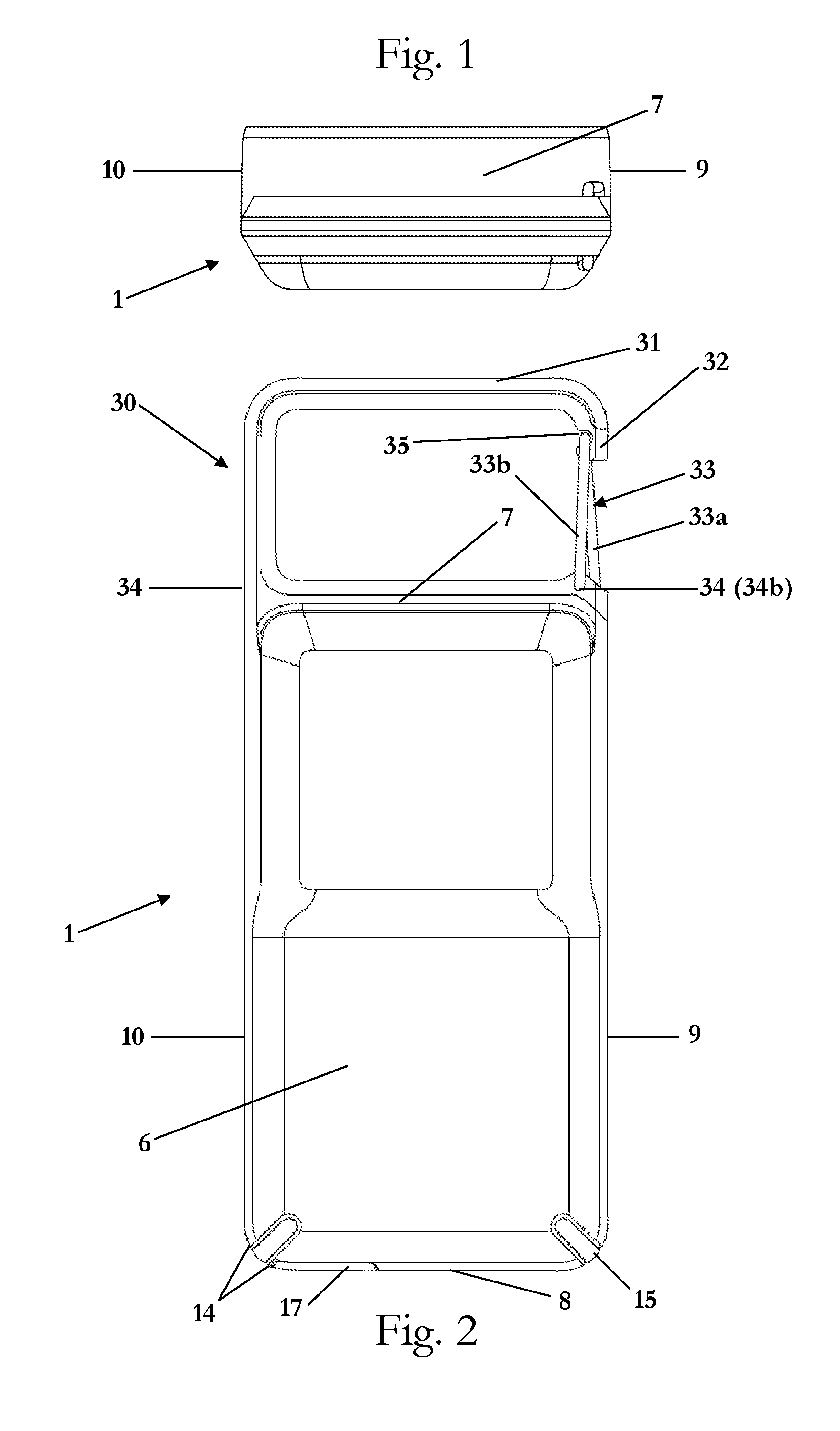
[0029] FIG. 1 is an upper side view of the case in accordance with an embodiment of the invention.
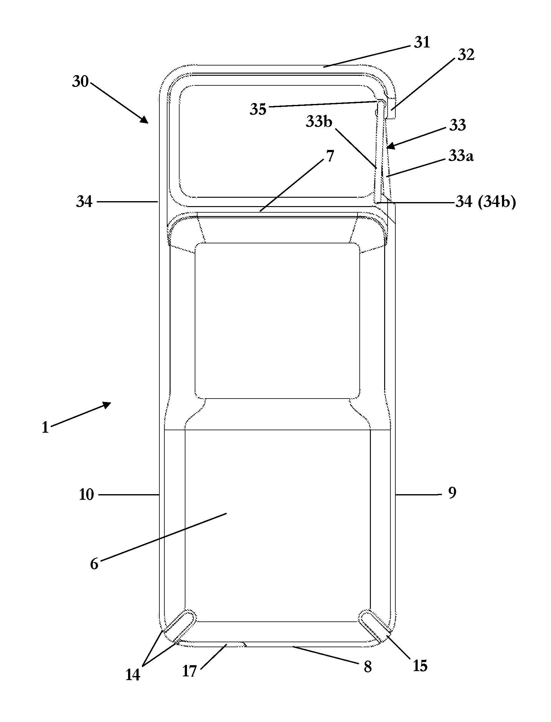
[0030] FIG. 2 is a rear view of the case in accordance with an embodiment of the invention.
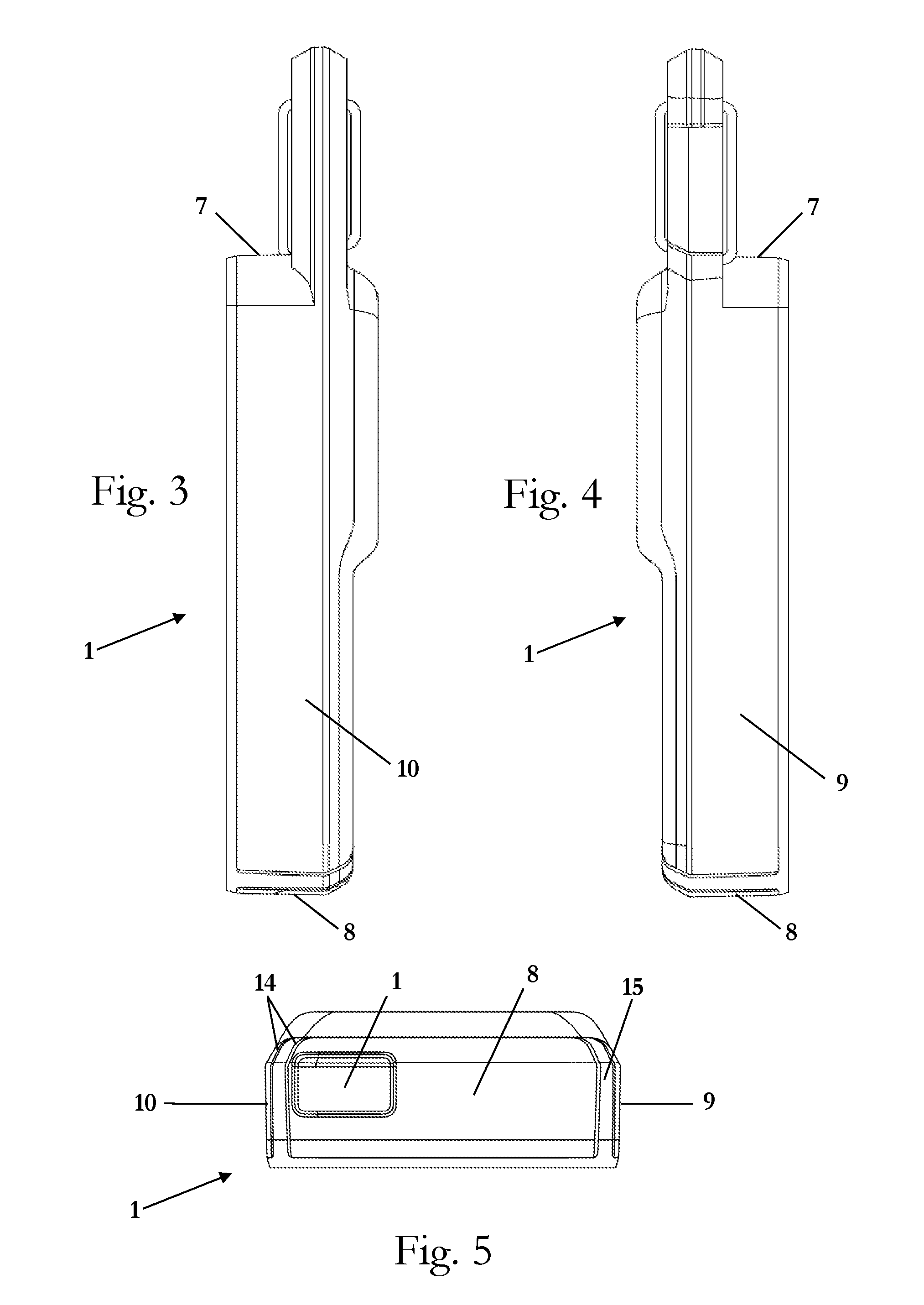
[0031] FIG. 3 is a right side view of the case in accordance with an embodiment of the invention.
[0032] FIG. 4 is a left side view of the case in accordance with an embodiment of the invention.
[0033] FIG. 5 is a lower side view of the case in accordance with an embodiment of the invention.
[0034] FIG. 6 is a front view of the case in accordance with an embodiment of the invention.
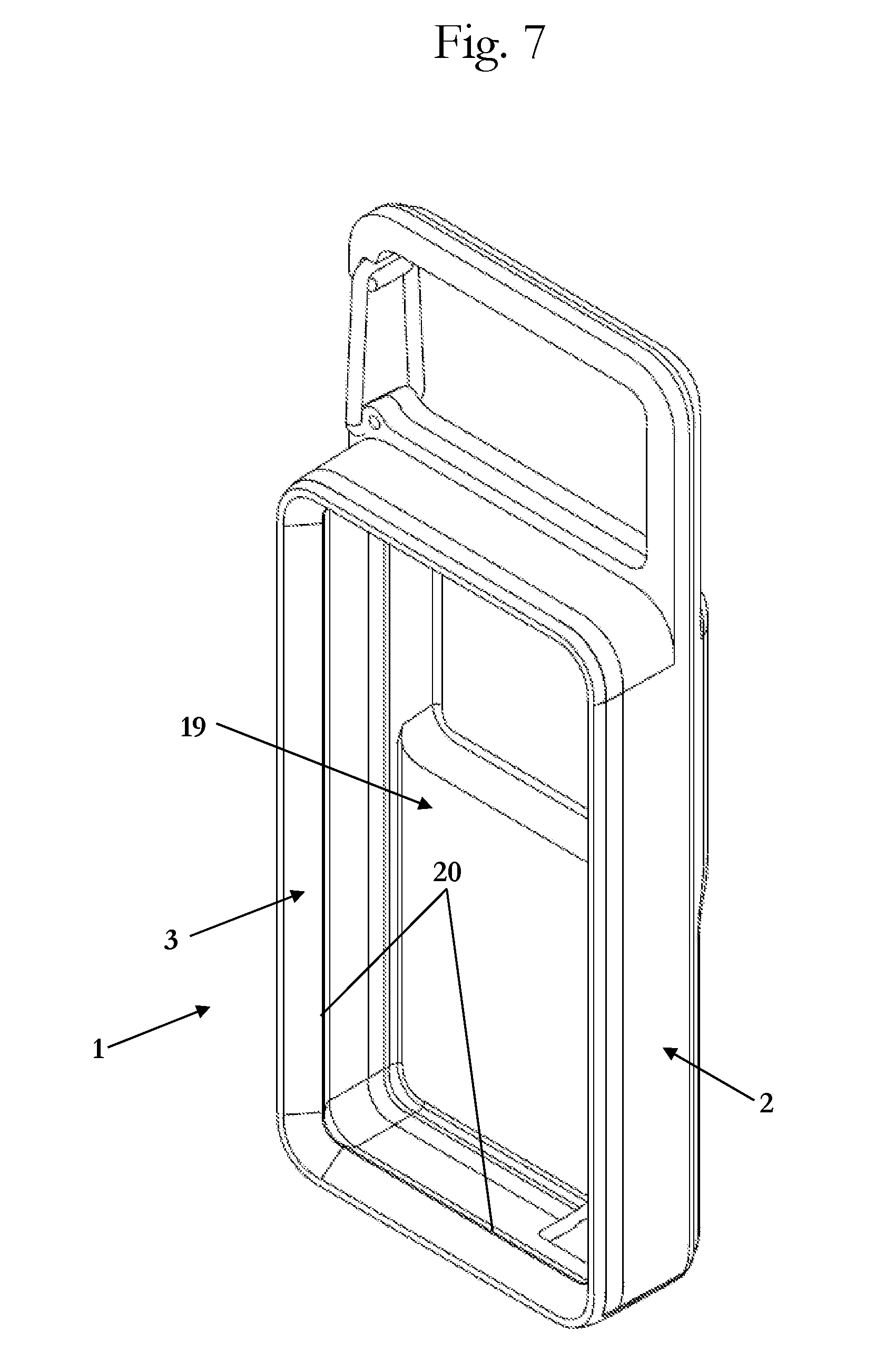
[0035] FIG. 7 is a front-right perspective view of the case in accordance with an embodiment of the invention.
[0036] FIG. 8 is a front-right expanded view of the case in accordance with an embodiment of the invention.
DETAILED DESCRIPTION OF EMBODIMENTS
[0037] It is to be understood that the figures and descriptions of the present invention have been simplified to illustrate elements that are relevant for a clear understanding of the present invention, while eliminating, for purposes of clarity, many other elements which are conventional in this art. Those of ordinary skill in the art will recognize that other elements are desirable for implementing the present invention. However, because such elements are well known in the art, and because they do not facilitate a better understanding of the present invention, a discussion of such elements is not provided herein.
[0038] The present invention will now be described in detail on the basis of exemplary embodiments. It is noted that any numerical ranges disclosed herein are included to individually disclose every sub-range and number, both whole integer and partial fraction, within the disclosed range. For example, a disclosed range of 1-100 is intended to individually disclose 20-90, 40-80, 30.5-50.2, 20, 67.3, 84.512924, and every other range and number that falls within the recited range.
[0039] A case according to an embodiment of the invention can be arrived at by providing shock-absorbing impact geometry to the interior of the case in the form of triangular ridges that protrude from the inner surface of the sides of the case. The narrow tops of the ridges contact the surface of the device. When force is applied between the outside of the case and the device, such as during an impact event, the force causes the triangular ridges to deform against the surface of the device. As force increase, further deformation of the ridges increases the volume of deformed material. This configuration allows the case to absorb impact and reduce the forces communicated to a device within the case in the event the device and case are dropped on a hard surface.
[0040] FIGS. 1-8 show an upper side view, a rear view, a right side, a left side view, a lower side view, a front view, a front view, a front-right perspective view, and a front-right expanded view, respectively, of the case in accordance with an embodiment of the invention. The case 1 includes a first layer or shell 2 and a second layer 3. The first layer or shell 2 includes a rear side having an inside surface 4 and an outside surface 6 opposite to the inside surface. An upper side 7, a lower side 8, a left side 9, and a right side 10 extend from the outside surface 6 of the rear side toward a front of the case 1 so as to form a pocket or recess in which the second layer 3 will be--and eventually a mobile device can be--arranged. The second layer 3 also includes a corresponding rear side having an inside surface 21, as well as one or more of corresponding upper, lower, left, and right sides. A pocket or recess 19 may be formed in second layer 3 for receiving the mobile device.
[0041] In one embodiment, the rear sides of the first layer 2 and second layer 3 overlay each other. The rear sides of the first layer or shell 2 and second layer 3 are also preferably substantially coextensive with each other so that the rear side of each layer covers at least 50% of the surface area of the rear side of the other layer. It is also preferable that the respective upper sides, lower sides, left sides, and right sides of the first layer 2 and second layer 3 are substantially coextensive with each other so that the respective upper sides, lower sides, left sides, and right sides of each layer covers at least 50% of the surface area of the corresponding side of the other layer. Additionally, it is preferable that the rear of the case (formed by the rear sides of the first layer 2 and second layer 3) is configured to cover at least 90%, if not all, of the rear of a mobile device when the mobile device is arranged within the case.
[0042] According to another embodiment, the respective upper sides, lower sides, left sides, and right sides of the first layer 2 and second layer 3 are only partially coextensive with each other so that the respective upper sides, lower sides, left sides, and right sides of the first layer 2 cover only a portion of the respective sides of the second layer 3.
[0043] The first layer or shell 2 is preferably formed from a rigid or hard nonmetallic material that is RF-transparent to create a rigid/hard outer shell which provides at least some impact protection as well as protection from being punctured by impacts with sharp objects. Examples of suitable nonmetallic RF-transparent hard/rigid materials include hardened plastic material, a rigid or semi-rigid plastic material, a rigid/hard rubber material, a polycarbonate material, a para-aramid material, wood, glass, quartz, and any combination thereof, and may be any color or texture. Preferred materials include thermosetting plastics with a hard durometer having shore 30D to shore 100D, polycarbonate, poly(methyl methacrylate) ("PMMA"), acrylonitrile butadiene styrene ("ABS"), PMMA, polyethylene terephthalate ("PET"), high durometer thermoplastic elastomers ("TPEs") and thermoplastic polyurethanes ("TPUs") having shore 30D to shore 100D, and any combination thereof. The hard protective exterior shell may be designed to mimic the finish of existing mobile devices, such as phones, MP3/4 players, tablets, laptops, electronic safety devices, and other mobile electronic devices. Many users like the feel of the original electronic device and would like to maintain that feel but still want protection for their device. The hard protective exterior shell of the present invention has a low coefficient of friction. This allows the device to be slipped in and out of pockets easily with little resistance and without gripping to clothing materials--a major complaint from users when an elastomeric material is used for the outside of cases.
[0044] The outside surface of the first layer or shell 2 is may be provided with a scratch resistant UV hardcoat, which resists scratches and prevents discoloration of the case due to UV exposure.
[0045] The second layer 3 is preferably formed from a nonmetallic RF-transparent soft elastomeric material which provides at least some shock protection from impact events such as drops or falls. Examples of suitable materials include thermoplastic elastomers ("TPEs"), thermoplastic polyurethane ("TPU"), polyolefins, silicone, rubber, and any combination thereof. The second layer 3 may also be designed so that there are no gaps between the rear of the mobile device and the inside surface 21 of the rear side of the case. This enables the case to have a very solid connection to the mobile electronic device. The second layer 3 may additionally be formed with a lip or rim 20 so as to secure and retain the mobile device within the case 1. The elastomeric layer 3 also can be formed to have portions designed to cover buttons on a mobile device. This allows a user to simply press the exposed portion of the inner elastomeric layer corresponding to the desired input of the mobile device.
[0046] The second layer 3 may also, or alternatively, be formed from a nonmetallic RF-transparent non-Newtonian dilatant material. The dilatant material is soft and flexible when at rest, but stiffens and/or hardens upon impact. In this way, the dilatant material is able to provide both impact protection by dispersing the force of an impact event along the surface of the second layer 3, and shock protection by absorbing some of the shock force of the impact event. This dual quality (i.e., absorbing and diffusing impact or impact forces) of the dilatant material allows for less material to be used to make the case--allowing for a thinner, lighter, and less bulky case which increases the portability of the protected mobile device--while still providing increased impact and shock protection to the mobile device encased therein.
[0047] Examples of suitable dilatant materials for the second layer 3 include materials made by D3O.RTM. (such as D3O.RTM. ST, D3O.RTM. XT, D3O.RTM. Shock+, and D3O.RTM. Aero), PORON.RTM. XRD.TM. made by Rogers Corporation, and ARTi-LAGE.TM. artificial cartilage foam made by ARTiLAGE.TM.. Impact absorbing materials (such as foams) which have dilatant properties are especially preferred.
[0048] The dilatant material may have a hardness of at least 20 Shore OO, or may have a hardness of at least 5 Shore O. Preferably the hardness is at least 30 Shore OO, at least 50 Shore OO, at least 60 Shore OO, or at least 70 Shore OO. More preferably the hardness is in a range of 20-90 Shore OO, or in a range of 5-61 Shore O. More preferably still, the hardness is in a range of 30-80 Shore OO, or in a range of 5-40 Shore O. Even more preferably, the hardness is in a range of 40-70 Shore OO.
[0049] Preferably the second layer 3 has a hardness in the range of from 60-85 Shore A. If the second layer 3 is clear, its preferred hardness is 75-85 Shore A. If the second layer 3 is opaque, its preferred hardness is 60-75 Shore A.
[0050] Certain additives can cause an otherwise non-metallic RF-transparent material to materially interfere with the transmission of radio frequencies. Examples include carbon, which may be added to color some plastics materials black. In a preferred embodiment, the non-metallic RF-transparent material is non-black so as to avoid this issue. Other examples of RF-interfering additives include metallic flakes and other reflective glitter flakes, which are also preferably not included in or added to the current protective case.
[0051] Each of the first layer 2 and rear side of the second layer 3 is 0.5-4.0 mm thick. Preferably one or more of the layers is 0.6-3.0 mm thick. More preferably, one or more of the layers is 0.8-2.0 mm thick. Even more preferably, one or more of the layers is 0.9-1.3 mm thick.
[0052] The first layer 2 and second layer 3 may be co-molded/co-casted together or otherwise permanently affixed to each other, such as with an adhesive.
[0053] Alternatively, the first layer 2 and second layer 3 may be separable from one another as two distinct pieces. In such an instance, the two layers can be configured so that they mechanically engage with each other to form a unitary case. For example, the first layer 2 may be designed with slots or cutouts 14 into which corresponding ridges or ribs 15 of the second layer 3 engage (e.g., by snapping, pressure fitting, or any other suitable mechanical engagement). As another example opposite sides of the first layer 2 (e.g., upper side 7 and lower side 8, left side 9 and right side 10, or both) may be designed to snap onto and hold the second layer 3.
[0054] For example, one process for producing the case may be: [0055] 1. Mold the first layer 2; and [0056] 2. Place the first layer 2 into the overmold tool, and mold the second layer 3 onto the first layer 2.
[0057] Another example of a process for producing the case may be: [0058] 1. Mold the second layer 3; and [0059] 2. Place the second layer 3 into the overmold tool, and mold the first layer 2 onto the second layer 3.
[0060] Yet another example of a process for producing the case may be: [0061] 1. Mold the first layer 2; [0062] 2. Mold the second layer 3 (separately from, and before, after, or simultaneously with, the first layer 2); and [0063] 3. Join together the first layer 2 and the second layer 3.
[0064] It is noted that additional openings or cutouts 17 may be provided in at least a part of the case 1 so as to allow various buttons, ports, or features of a protected mobile device to be accessed without having to remove the mobile device from the case 1. For example openings or cutouts 17 may be provided to allow a user to engage a button of the protected mobile device either directly or via the cover portion 11 of the layer 3. As another example, cutouts 17 may be provided to create an opening in the case 1 though which a charging port, audio port, data port, or other electrical port of the mobile device may be accessed, either directly or via a pass-through connection. As yet another example, cutouts 17 may be provided to create an opening to expose a camera lens, audio speaker, microphone, or other feature of the device to be accessed or employed without removing the mobile device from the case 1.
[0065] In one embodiment, at least a portion of each of the first layer 2 and the second layer 3, corresponding to the rear of the case 1, is translucent, transparent, or clear, with a visible light transmittance (VLT) of at least 20%, so that the rear of a mobile device arranged in the case can be seen by a user through the first layer 2 and the second layer 3. Preferably, the portions of the first layer 2 and the second layer 3, corresponding to the rear of the mobile device, are translucent or clear. For example, at least a portion, if not all, of the first layer 2 may have a VLT of at least 20%, preferably at least 50%, more preferably at least 80%, more preferably still at least 90%, and most preferably 100%. Similarly, at least a portion, if not all, of the second layer 3 may have a VLT of at least 20%, preferably at least 50%, more preferably at least 80%, more preferably still at least 90%, and most preferably 100%.
[0066] The first layer 2 may also include relief slots or cutouts 14 in the hard material that allow the case to flex during installation and removal. Corresponding ridges or ribs 15 of the second layer 3 engage into the slots or cutouts 14. The second layer 3 includes the shock-absorbing impact geometry in the form of triangular ridges 4, as described above.
[0067] The case 1 includes a clip portion 30 that is integral with the rest of the case, and which forms a ring. The clip portion 30 is formed by an external clip portion 31, an internal clip portion 32, and a hinged gate 33. The external clip portion 31 extends from the upper side 7 of the first layer or shell 2 and is formed from a rigid or hard nonmetallic material that is RF-transparent, such as those materials mentioned above. Preferably the external clip portion 31 is formed by the first layer 2 itself. The internal clip portion 32 is arranged inside the external clip portion 31, and is also formed from one of the rigid or hard nonmetallic RF-transparent materials mentioned above. The internal clip portion 32 may be formed from the same type of material as the external clip portion 31, or may be formed from a different type of material. Preferably, the internal clip portion 32 is permanently attached to the external clip portion 31.
[0068] Preferably, a thickness of the internal clip portion 32 in a radial direction of the ring formed by the clip portion 30 is greater than a thickness of the external clip portion 31 in the radial direction of the ring. In one such embodiment, the thickness of the external clip portion 32 is 1.5 mm or less, preferably 0.50 mm to 1.50 mm, more preferably 1.00 mm to 1.30 mm, most preferably around 1.20 mm. In this embodiment, the thickness of the internal clip portion is 1.2 mm or more, preferably 1.20 mm to 10.00 mm, more preferably 1.20 mm to 5.00 mm, most preferably 1.30 mm to 3.00 mm.
[0069] This two-piece design with the internal clip portion 32 being thicker than the external clip portion 31 avoids certain problems that might arise compared to a single-piece design with an external clip portion 31 that is significantly thicker than the other portions of the first layer 2. In particular, molding a single piece that varies in wall thickness significantly may result in a variety of defects in the molded piece, such as shrinking, bubbles, brittleness, and stress concentration. These defects can weaken the integrity of the case, cause cosmetic imperfections, cause structural failures, or deform the shape of the case. By forming the internal clip portion 32 separately from and thicker than the external clip portion 31, the strength and integrity of the clip portion 30 can be maintained and even increased compared to a single piece of material of the same thickness as the external and internal clip portions 31,32 combined. In addition, this configuration allows the external clip portion 31 to be formed from the first layer 2 at a comparable thickness to the rear side 4,6, upper side 7, lower side 8, left side 9, and right side 10, thereby avoiding the above-mentioned problems.
[0070] In one embodiment, the internal clip portion 32 has a protrusion or ridge 36 that extends from periphery of the internal clip portion 32. The external clip portion 31 has a corresponding indentation or groove 37 into which the protrusion or ridge 36 extends when the internal clip portion 32 is arranged inside the external clip portion 31. This further secures the internal clip portion 32 inside the external clip portion 31 and strengthens the clip portion 30.
[0071] The hinged gate 33 may be formed from one of the rigid or hard materials mentioned above. Additionally, the hinged gate 33 may be formed from a metal or alloy. Preferably, no part of the case 1 is formed from a metallic or RF-blocking material other than the hinged gate 33, which may or may not be formed from a metal or alloy. The hinged gate 33 connects to the rest of the case 1 via a hinge portion 34, around which the hinged gate 33 is rotatable between a closed position in which part of the hinged gate 33 rests against a recess 35 formed in the external clip portion 31 or the internal clip portion 32 so that the clip portion 30 forms a closed ring with the rest of the case, and an open position in which the clip does not rest in the recess 35 so that the clip portion 30 forms an open ring with the rest of the case.
[0072] In one embodiment, the hinged gate 33 includes two legs 33a,33b which are offset from each other. In this embodiment, the hinge portion 34 includes two holes or indentations 34a,34b that are similarly offset from each other. The end of leg 33a extends into the hole 34a and the end of the leg 33b extends into the hole 34b. This creates a spring force that biases the hinged gate 33 in the closed position.
[0073] By forming the first layer 2, second layer 3, the external clip portion 31, and the internal clip portion 32 from nonmetallic RF-transparent materials, the case 1, as a whole, can be made RF-transparent so that RF signals can be sent and received by a mobile device arranged in the case 1.
[0074] In a preferred embodiment, the second layer forms the external clip portion 31, and the first layer 2, second layer 3, and internal clip portion 32 are injection molded as three separate parts that are then co-molded together as a visually singular part that is both transparent and durable. The metal swinging gate 33 is than attached to the case 1. This design not only protects the device and allows it to be worn on many different areas of the user, but also makes the electronic device visible to the use through the transparent case 1.
[0075] While the embodiments of the case 1 shown in the drawing have separate layers 2,3 forming the interior and exterior of the case 1, the interior and exterior of the case 1--including the external clip portion 31--can alternatively be made of a single layer 3, into which the internal clip portion 32 is placed.
[0076] While the embodiments of the case 1 shown in the drawing are made from the two layers 2, 3, it can also be made of a single layer 2 or 3 that forms both the interior and exterior of the case 1.
[0077] It is noted that the terminology used above is for the purpose of reference only, and is not intended to be limiting. For example, terms such as "upper", "lower", "above", "below", "rightward", "leftward", "clockwise", and "counterclockwise" refer to directions in the drawings to which reference is made. As another example, terms such as "inward" and "outward" may refer to directions toward and away from, respectively, the geometric center of the component described. As a further example, terms such as "front", "rear", "side", "left side", "right side", "top", "bottom", "horizontal", and "vertical" describe the orientation of portions of the component within a consistent but arbitrary frame of reference which is made clear by reference to the text and the associated drawings describing the component under discussion. Such terminology will include the words specifically mentioned above, derivatives thereof, and words of similar import.
[0078] While this invention has been described in conjunction with the specific embodiments outlined above, it is evident that many alternatives, modifications, and variations will be apparent to those skilled in the art. Accordingly, the preferred embodiments of the invention as set forth above are intended to be illustrative, not limiting. Various changes may be made without departing from the spirit and scope of the inventions as defined in the following claims.
[0079] In addition, it is noted that citation or identification of any document in this application is not an admission that such document is available as prior art to the present invention.
* * * * *
D00000
D00001
D00002
D00003
D00004
D00005
XML
uspto.report is an independent third-party trademark research tool that is not affiliated, endorsed, or sponsored by the United States Patent and Trademark Office (USPTO) or any other governmental organization. The information provided by uspto.report is based on publicly available data at the time of writing and is intended for informational purposes only.
While we strive to provide accurate and up-to-date information, we do not guarantee the accuracy, completeness, reliability, or suitability of the information displayed on this site. The use of this site is at your own risk. Any reliance you place on such information is therefore strictly at your own risk.
All official trademark data, including owner information, should be verified by visiting the official USPTO website at www.uspto.gov. This site is not intended to replace professional legal advice and should not be used as a substitute for consulting with a legal professional who is knowledgeable about trademark law.