Ultra-low Thermal Conductivity Diving Suit Material For Enhanced Persistence In Cold Water Dives
Buongiorno; Jacopo ; et al.
U.S. patent application number 16/462470 was filed with the patent office on 2019-09-05 for ultra-low thermal conductivity diving suit material for enhanced persistence in cold water dives. The applicant listed for this patent is Massachusetts Institute of Technology. Invention is credited to Matteo Brucci, Jacopo Buongiorno, Anton Cottrill, Jeffrey Moran, Michael Strano.
| Application Number | 20190269187 16/462470 |
| Document ID | / |
| Family ID | 62145878 |
| Filed Date | 2019-09-05 |


| United States Patent Application | 20190269187 |
| Kind Code | A1 |
| Buongiorno; Jacopo ; et al. | September 5, 2019 |
ULTRA-LOW THERMAL CONDUCTIVITY DIVING SUIT MATERIAL FOR ENHANCED PERSISTENCE IN COLD WATER DIVES
Abstract
Disclosed are ultra-low thermal conductivity fabrics, methods for preparing them and methods of using them, in particular as diving suit materials for enhanced persistence in cold-water dives.
| Inventors: | Buongiorno; Jacopo; (Burlington, MA) ; Strano; Michael; (Lexington, MA) ; Moran; Jeffrey; (Jamaica Plain, MA) ; Brucci; Matteo; (Boston, MA) ; Cottrill; Anton; (Cambridge, MA) | ||||||||||
| Applicant: |
|
||||||||||
|---|---|---|---|---|---|---|---|---|---|---|---|
| Family ID: | 62145878 | ||||||||||
| Appl. No.: | 16/462470 | ||||||||||
| Filed: | November 21, 2017 | ||||||||||
| PCT Filed: | November 21, 2017 | ||||||||||
| PCT NO: | PCT/US17/62775 | ||||||||||
| 371 Date: | May 20, 2019 |
Related U.S. Patent Documents
| Application Number | Filing Date | Patent Number | ||
|---|---|---|---|---|
| 62424828 | Nov 21, 2016 | |||
| Current U.S. Class: | 1/1 |
| Current CPC Class: | B63C 11/04 20130101; A41D 13/012 20130101; A41D 31/06 20190201; A41D 13/002 20130101 |
| International Class: | A41D 31/06 20060101 A41D031/06; A41D 13/012 20060101 A41D013/012; A41D 13/002 20060101 A41D013/002; B63C 11/04 20060101 B63C011/04 |
Goverment Interests
GOVERNMENT SUPPORT
[0002] This invention was made with government support under Grant No. N00014-16-1-2144, awarded by the Office of Naval Research. The government has certain rights in the invention.
Claims
1. A thermally insulating fabric comprising a polymeric material infused with a high molecular weight gas.
2. The thermally insulating fabric of claim 1, wherein the fabric is water compatible.
3. The thermally insulating fabric of claim 1, wherein the fabric is substantially water resistant or waterproof
4. The thermally insulating fabric of claim 1, wherein the polymeric material comprises neoprene foam, polystyrene, or nitrile butadiene rubber.
5. The thermally insulating fabric of claim 1, wherein the high molecular weight gas is a noble gas.
6. The thermally insulating fabric of claim 5, wherein the high molecular weight gas is selected from the group consisting of xenon, krypton, and argon.
7. The thermally insulating fabric of claim 6, wherein the high molecular weight gas is xenon.
8. The thermally insulating fabric of claim 6, wherein the high molecular weight gas is argon.
9. The thermally insulating fabric of claim 1, wherein the thermally insulting fabric has a thermal conductivity of about 0.031 W/m-K.
10. The thermally insulating fabric of claim 1, wherein the thermally insulting fabric provides thermal protection in harsh environments.
11. The thermally insulating fabric of claim 1, wherein the polymeric material comprises neoprene foam.
12. (canceled)
13. A flexible garment comprising the thermally insulating fabric of claim 1.
14.-25. (canceled)
26. A dive suit comprising the thermally insulating fabric of claim 1.
27.-36. (canceled)
37. A method of preparing a thermally insulating fabric of claim 1, comprising: placing a fabric in a sealed container; and filling the sealed container with an insulating gas; thereby forming the thermally insulating fabric of claim 1.
38.-45. (canceled)
46. The method of claim 37, wherein the container is filled with the insulating gas to a pressure of about 10-50 psi or about 20 psi.
47. The method of claim 37, wherein the method further comprises maintaining the pressure of the container from about 1 hour to about 100 hours.
48.-52. (canceled)
53. A method for protecting a diver in a cold-water environment, comprising clothing a diver in the dive suit of claim 26.
54.-56. (canceled)
57. The method of claim 53, wherein the method reduces the diver's risk for hyperthermia.
58. The method of claim 53, wherein the method allows the diver to stay in the cold water environment for at least about two hours, or about two hours to about three hours.
59. The method of claim 58, wherein the cold water has a temperature of 10.degree. C. or less.
Description
RELATED APPLICATIONS
[0001] This application claims the benefit of priority to U.S. Provisional Patent Application Ser. No. 62/424,828, filed Nov. 21, 2016.
BACKGROUND
[0003] Underwater diving, as a human activity, is the practice of descending below the water's surface to interact with the environment. Immersion in water and exposure to high ambient pressure have physiological effects that limit the depths and duration possible in ambient pressure diving. This is because humans are not physiologically and anatomically well adapted to the environmental conditions of diving. In particular, in cold-water environments (e.g., water at less than 10.degree. C.) a diver is at risk of developing hypothermia. Current diving garments only allow a diver to stay in the water for less than an hour. In some cases, however, divers need to stay in the water for more than an hour, such as for deep-sea exploration or for military recognizance missions. Accordingly, there remains a need in the art for improved diving garments that reduce a diver's risk of hypothermia, especially during long dive times.
SUMMARY
[0004] Provided herein are thermally insulating fabrics comprising a polymer infused with a high molecular weight gas. Also provided herein is a flexible garment comprising a neoprene foam infused with a high molecular weight gas. In some embodiments, the flexible garment is a dive suit, such as a wetsuit, a variable volume drysuit, a hot water wetsuit, or an active diver thermal protection system.
[0005] Also provided herein is a method for preparing the thermally insulating fabrics described herein comprising placing fabric in a sealed container; and filling the container with an insulating gas. In some embodiments, the fabric comprises a polymeric material (e.g., neoprene, polystyrene, or nitrile butadiene rubber). In some embodiments, the insulating gas is a high molecular weight gas, such as a noble gas (e.g., xenon, krypton, or argon).
[0006] Also provided herein are methods for protecting a diver in cold water environments, comprising providing a diver with a thermally insulating fabric (e.g., such as those used in dive suits) described herein. In some embodiments, the method further comprises reducing the diver's risk for hyperthermia. In other embodiments, the method further comprises allowing the diver to stay in the cold-water environment from about two hours to about three hours.
BRIEF DESCRIPTION OF THE DRAWINGS
[0007] FIG. 1A is an SEM image of unaltered neoprene foam. A magnified SEM is shown in the inset.
[0008] FIG. 1B shows an exemplary process flow for infusing insulating gases into neoprene foam.
[0009] FIG. 1C is a bar graph depicting thermal conductivities of neoprene foams when infused with the indicated gases. The experimental measurements are compared with those of the Maxwell's model, equation (1). Thermal conductivities for the gases considered in this work.sup.14: air (0.026 W/m-K), argon (0.018 W/m-K), krypton (0.0095 W/m-K), and xenon (0.0055 W/m-K). For experiments, the plotted data represent the average of at least 3 measurements and error bars represent one standard deviation in each direction. For the Maxwell data, error bars reflect uncertainty in the estimate due to uncertainty in the estimate of porosity from SEM images.
[0010] FIG. 1D is a line graph depicting the measured thermal conductivity of neoprene versus time for the indicated filling gases, as compared to the control (air). Gas discharge takes place over a time scale that depends mainly on the insulating gas. All measurements are estimated to be within 7% of the actual values.
[0011] FIG. 2A is a schematic showing discharging simulations, wherein the neoprene is filled with argon at 243 kPa at t=0.
[0012] FIG. 2B is a schematic showing a charging simulation, wherein the neoprene is initially filled with nitrogen (to approximate air) at atmospheric pressure and is placed in a pure atmosphere of argon at t=0.
[0013] FIG. 3A is a photograph of a thermal conductivity measurement apparatus, making use of the hot disk transient method. A nickel wire protected by a kapton covering ("Sensor/Source"), which acts as both the heat source and temperature sensor, is sandwiched between neoprene samples. They are held in place by a mild steel weight that provides light compressive stress (.about.0.01 bar), which keeps air cavities from forming between the sample and sensor (which would corrupt the measurement). The neoprene coupons are cut to have the same diameter as the weight so that the compressive stress is uniform on the sample surface.
[0014] FIG. 3B is a plot showing the thickness of argon-infused neoprene coupon as a function of time during gas discharge, as measured optically using a high-resolution USB camera. The solid black curve is a fit of the form ae.sup.-bt+c, where a=0.2092 cm, b=-0.058 hr.sup.-1, and c=0.4842 cm. In the simulations, the thickness varies in time according to this exponential fit curve. Each thickness measurement is the average of five individual measurements performed using ImageJ, and error bars represent one standard deviation in each direction.
[0015] FIG. 3C is a plot showing the thermal conductivity of argon-infused neoprene as a function of time for the discharging process compared with the predicted range from the finite-element simulation, showing good agreement.
[0016] FIG. 3D is s graph showing simulation predictions (curve) compared with experimental measurements of thermal conductivity as a function of charging time for argon-infused neoprene. Experimental data points represent the average of at least 3 measurements and error bars indicate one standard deviation in each direction.
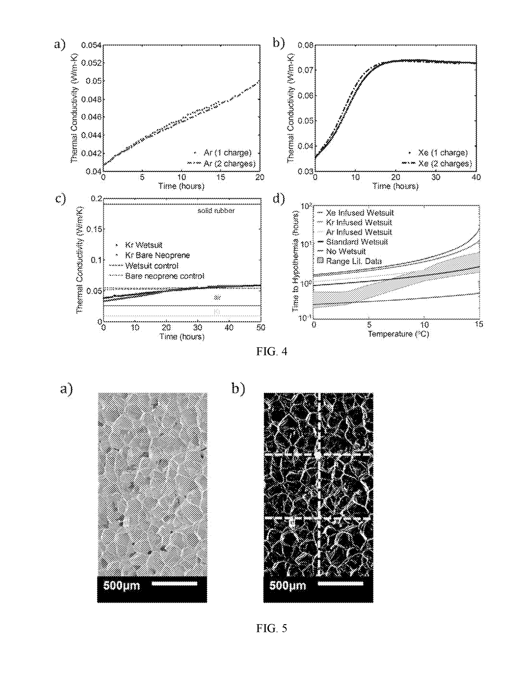
[0017] FIG. 4A is a graph showing reproducibility of Ar charging. The two data sets show the thermal conductivity vs time for one set of neoprene coupons, charged and then recharged with the gas.
[0018] FIG. 4B is a graph showing reproducibility of Xe charging. The two data sets show the thermal conductivity vs time for one set of neoprene coupons, charged and then recharged with the gas.
[0019] FIG. 4C is a plot showing thermal conductivity versus time for bare neoprene charged with krypton compared with data for a full wetsuit, also charged with krypton.
[0020] FIG. 4D is a graph showing predictions of equation (1) for the time to hypothermia (i.e., time required for core body temperature T.sub.core to decrease from the initial value, 37.degree. C., to T.sub.h=35.degree. C.) as a function of water temperature for no wetsuit and for wetsuits with the indicated gases. These data are compared to experimental data (shaded grey region) reported by Aguilella-Arzo et al. (Am. J. Phys., 2003, 71, 333-337).
[0021] FIG. 5A shows a scanning electron micrograph (SEM) image of unmodified neoprene.
[0022] FIG. 5B shows the SEM image from FIG. 5A converted to binary in ImageJ in order to estimate the porosity of the neoprene foam. The dashed lines indicate the six regions of interest used to calculate six values of porosity for the foam.
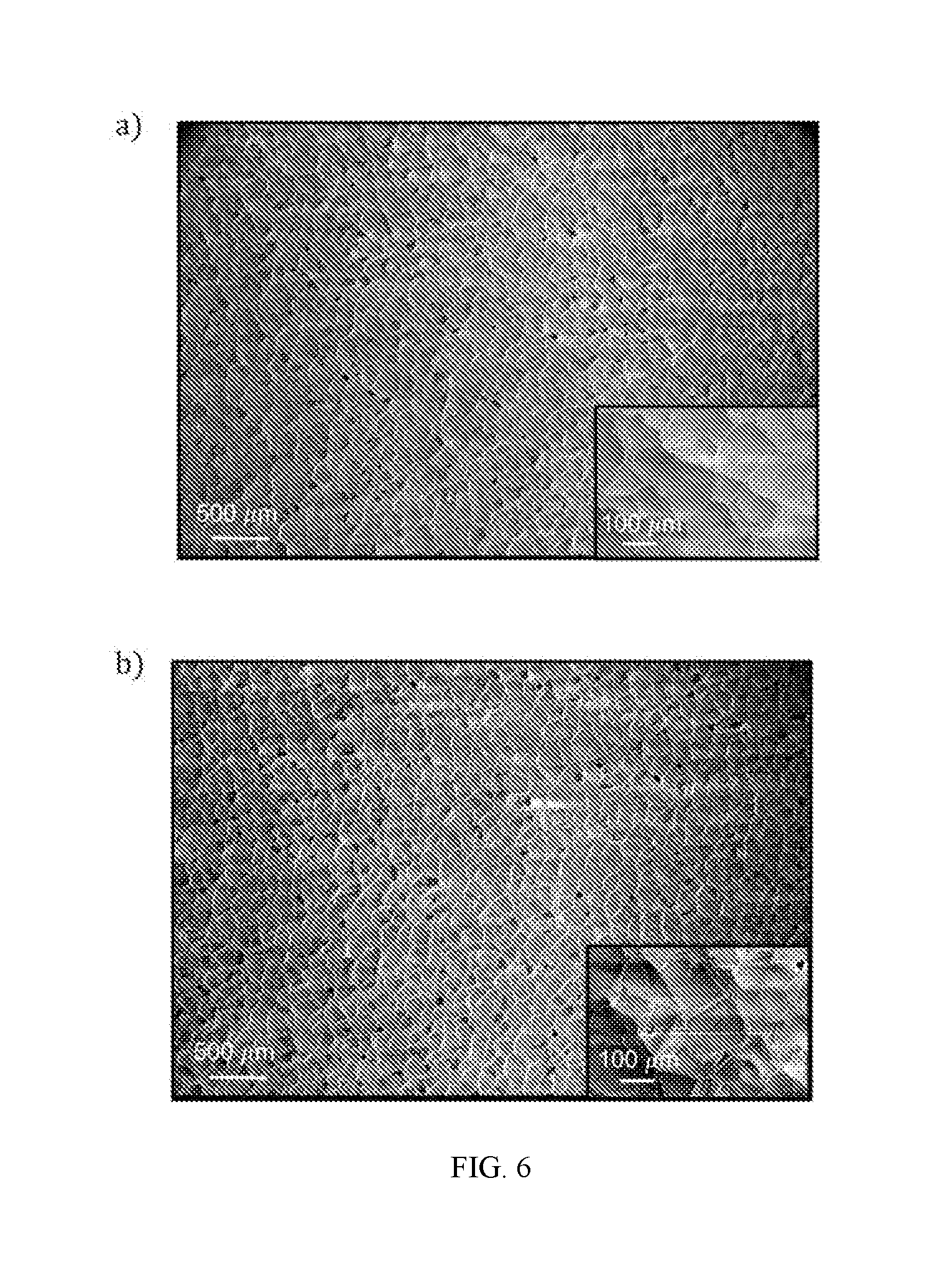
[0023] FIG. 6A shows an SEM image of a neoprene foam sample following charging with argon gas.
[0024] FIG. 6B shows an SEM image of a neoprene foam sample following charging with xenon gas.
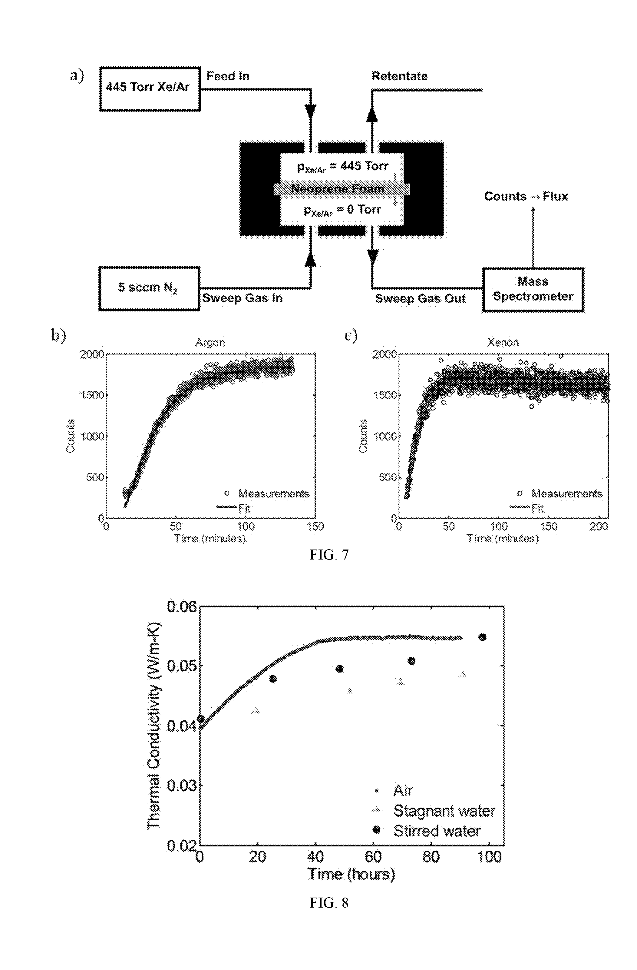
[0025] FIG. 7A shows an apparatus for measuring gas permeation through neoprene foam. Active area of the neoprene membrane is 6 cm.sup.2 and the thickness of the neoprene membrane is 1.6 mm.
[0026] FIG. 7B is a graph showing the experimentally measured mass spectrometer counts for argon as a function of time (symbols), along with a best-fit of equation (S8). From this curve fitting, an effective diffusivity of 1.9.times.10.sup.-10 m.sup.2/s is extracted for argon in neoprene foam.
[0027] FIG. 7D is a graph showing the mass spectrometer counts for xenon as a function of time (symbols). From this analysis, the effective diffusivity for xenon in neoprene foam is determined to be 3.967.times.10.sup.-10 m.sup.2/s.
[0028] FIG. 8 is a graph showing the thermal conductivity versus time for bare neoprene charged with argon and stored in air (points) and neoprene samples charged with argon and stored in stagnant (triangles) and stirred water (circles) in between measurements. This figure indicates that leakage of the insulating gas from the neoprene occurs more slowly in stirred water (simulating a swimming diver) than in air and is slowest in stagnant water.
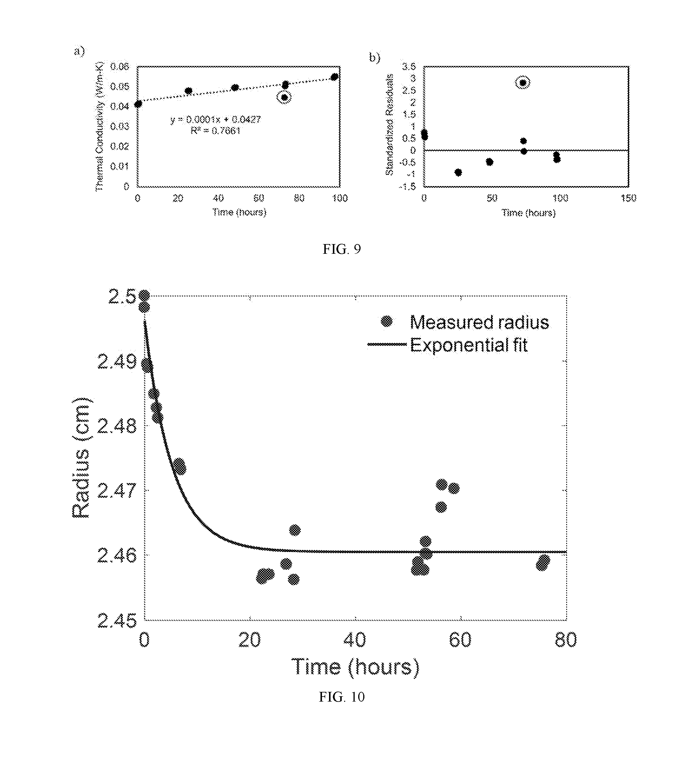
[0029] FIG. 9A is a graph showing the measured thermal conductivity as a function of time for argon-charged neoprene samples stored in stirred deionized water. The data are fitted to a linear regression, and the linear fit for the data is shown in the plot. The suspected outlier is circled.
[0030] FIG. 9B shows the standardized residuals for the linear fit in FIG. 9A. The suspected outlier is circled, and occurs almost three standard deviations from the fit.
[0031] FIG. 10 shows the radius of argon-infused neoprene disc (measured using optical images captured with USB camera and image analysis using ImageJ software) as a function of time after removal from the gas environment. Circles are experimental measurements and curve is a fit of the form r.sub.fit=ae.sup.-bt+c. Here the constants a, b, and c are 0.0357 cm, -0.1897 hr.sup.-1, and 2.4605 cm, respectively.
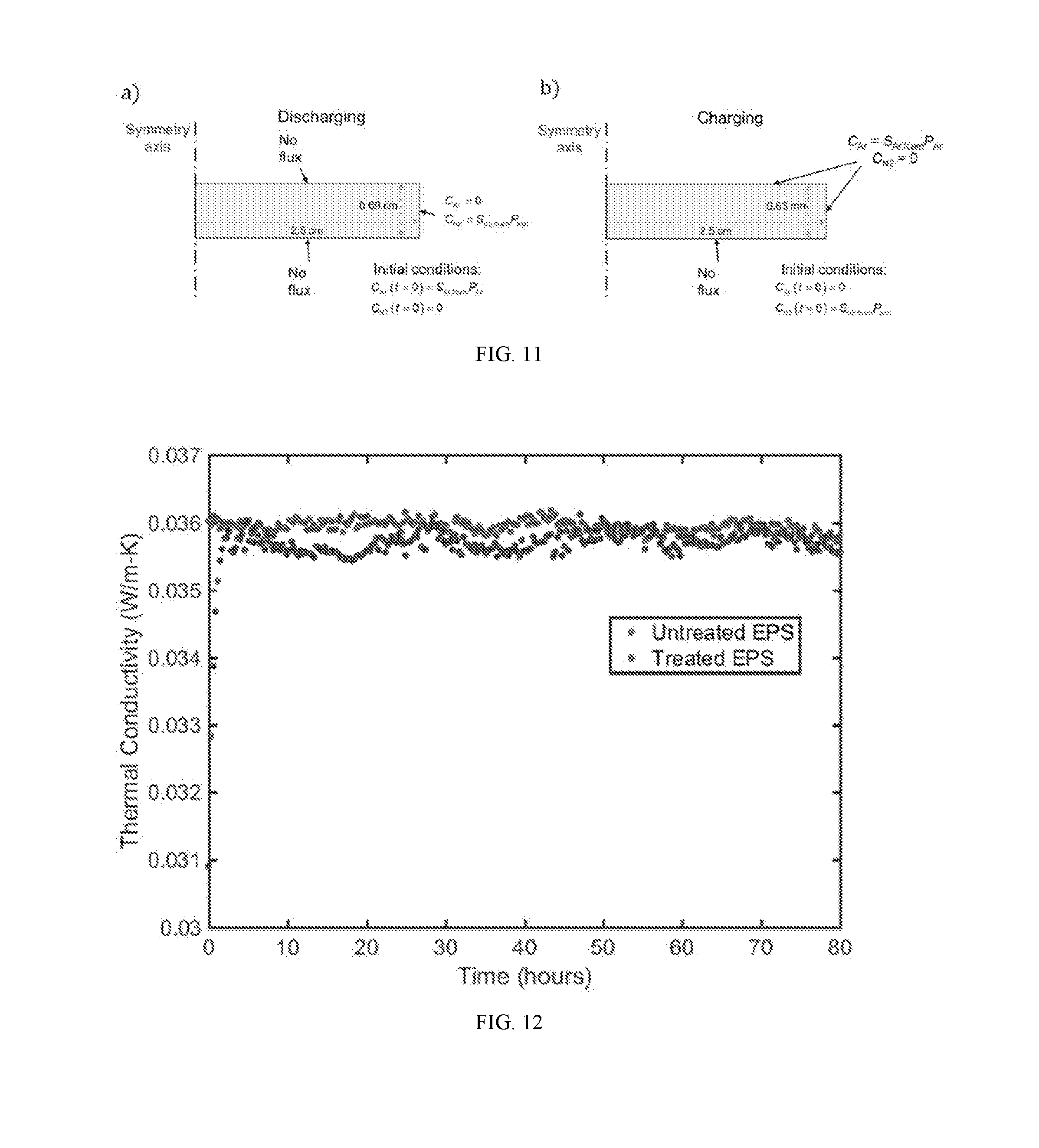
[0032] FIG. 11A shows a schematic of simulation domain showing dimensions, initial conditions, and boundary conditions assumed in the simulation.
[0033] FIG. 11B shows a schematic of charging simulations showing boundary and initial conditions. Gas flux through the bottom surface is ignored because the neoprene disc is assumed to sit flat on the bottom of the charging container.
[0034] FIG. 12 is a graph showing the thermal conductivity versus time for argon-infused expanded polystyrene (EPS) (black) and unmodified EPS (gray).
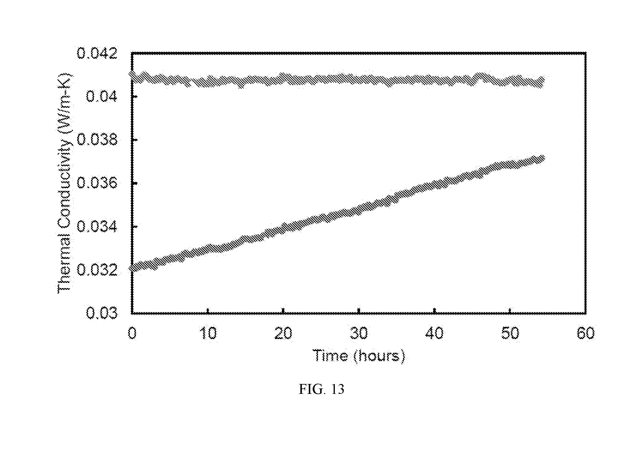
[0035] FIG. 13 is a graph showing the thermal conductivity versus time for argon-infused nitrile butadiene rubber, and air-infused nitrile butadiene rubber. (Control)
DETAILED DESCRIPTION
[0036] Thermally insulating fabrics are critical for human survival at low temperatures. This is especially true in water, where heat loss to the surroundings is much higher than in air, even at smaller temperature differences. High-performance thermally insulating garments (whose performance does not degrade in water) are becoming essential components for military divers, shipyard and underwater workers, and recreational open-water swimmers and triathletes. In general, foam insulation typically contains a low-thermal conductivity gas dispersed in a relatively low thermal conductivity matrix in an open or closed cell structure. The thermal conductivity of the composite is highly influenced by the thermal conductivities of the gas and matrix material; in addition, the cell size and type affect the effective thermal conductivity. (B. P. Jelle, Energy Build., 2011, 43, 2549-2563.)
[0037] Traditional thermal insulation materials comprise biopolymer-based materials, such as cork (thermal conductivity between 0.040-0.050 W/m-K) and cellulose (0.040-0.050 W/m-K), or fossil-fuel-derived polymeric foams, such as expanded polystyrene (0.030-0.040 W/m-K), extruded polystyrene (0.030-0.040 W/m-K), polyurethane (0.020-0.030 W/m-K), neoprene (0.050-0.060 W/m-K), and the like. Neoprene foams offer flexibility (capability of being shaped into a garment) and a closed cell nature (giving the material water resistance). (E. Bardy, J. Mollendorf and D. Pendergast, J. Phys. Appl. Phys., 2006, 39, 1908.)
[0038] In some embodiments, provided herein is a process for the non-destructive, repeatable fabrication of transient gas insulating materials (GIMs) from commercial closed-cell neoprene (also referred to as polychloroprene) foams.
[0039] In some embodiments, the methods disclosed herein are used to modify commercial neoprene in the form of a wetsuit. In some such embodiments, the methods disclosed herein reduce the thermal conductivity of the neoprene by up to about 40% (0.031 W/m-K), thereby achieving the lowest value for a flexible, water-resistant insulating material. As used herein, the term "flexible" refers to a material that can easily be used to form a garment that allows the user to move satisfactorily while underwater. In some embodiments, the thermal conductivity of the altered neoprene remains below the control value for more than 12 hours. Accordingly, the materials provided by the methods disclosed herein enhance insulation performance of foam neoprene-based garments, such as wetsuits.
[0040] The thermal conductivity of a gas scales linearly with its specific heat and inversely with the square root of its molecular weight. (G. Chen, Nanoscale Energy Transport and Conversion: A Parallel Treatment of Electrons, Molecules, Phonons, and Photons, Oxford University Press, 2005.) To this end, the insulating gas used in the methods disclosed herein must be a monatomic (low specific heat) and high-molecular-weight gas.
[0041] Earlier studies used krypton-xenon mixtures and argon as blowing agents for foam insulation. (See, e.g., U.S. Pat. No. 5,266,251A; K. Dey, C. Jacob and M. Xanthos, J. Vinyl Addit. Technol., 1996, 2, 48-52). These techniques were not widely adopted as a result of the significant leakage rate and replacement by ambient air that the foams experience following manufacturing. The methods disclosed herein overcome these issues. Indeed, the methods disclosed herein demonstrate that commercial, closed-cell foams can be infused with the high molecular weight, noble gases in a non-destructive and repeatable fashion at any point post-fabrication. In some embodiments, the methods disclosed herein are used with fabrics comprising neoprene foams. Such fabrics are critical for extending dive persistence in near 0.degree. C. water.
[0042] Neoprene foam conducts thermal energy such that a wetsuit wearer can only spend less than one hour in near-freezing water before becoming susceptible to hypothermia. The ultra-low thermal conductivity garments produced by the methods disclosed herein are capable of drastically extending dive times by reducing the rate of heat loss of the wearer. Taken together, the methods disclosed herein provide a simple technique enhancing the insulating performance of foam composite materials. Further, the methods provided herein extend the possible duration of recreational, industrial and military activities in water.
Material Synthesis
[0043] Foam neoprene is a closed-cell elastomeric foam consisting of gaseous cells dispersed within a solid neoprene rubber (polychloroprene) matrix (FIG. 1A). The gaseous phase of neoprene foam typically contains nitrogen or air, with thermal conductivity k.sub.g=0.026 W/m-K (at 25.degree. C.). Due to the high volume fraction of the gas (typically >70%) and heat partitioning between the gas and rubber phases, the inclusion of the gas phase leads to a reduction in the overall thermal conductivity of the material. However, air is not the most effective insulator among gases at room temperature.
[0044] Xenon (Xe), krypton (Kr) and argon (Ar) all possess lower thermal conductivities than air and are chemically inert, making them attractive candidates to replace air and enhance the insulating capabilities of neoprene foam. Accordingly, in some embodiments, the methods disclosed herein use Xe as an insulating gas. In other embodiments, the methods disclosed herein use Kr as an insulating gas. In still other embodiments, the methods disclosed herein use Ar as an insulating gas.
[0045] FIG. 1A shows a scanning electron micrograph (SEM) of a standard, commercial neoprene foam, which is characterized by approximately spherical pores with diameters in the range of 100-200 .mu.m. The pores contain a mixture of nitrogen and oxygen (air) as the filling gas, and the pores are dispersed within a neoprene rubber matrix. The porosity (gas volume fraction) of the neoprene foam was calculated at 83.+-.2% from image analysis of SEMs of the neoprene foam. The thermal conductivities of the gases were also considered, and measured at room temperature, at 0.026 W/m-K (air), 0.018 W/m-K (argon), 0.0095 W/m-K (krypton), and 0.0055 W/m-K (xenon). The effect of replacing the standard neoprene filling gas with a lower-thermal-conductivity gas can be predicted using Maxwell's homogeneous medium model, which has been shown to capture the effective thermal conductivity of neoprene foams, k.sub.f, reasonably well:
k f = k r k g + 2 k r + 2 ( k g - k r ) .phi. k g + 2 k r - ( k g - k r ) .phi. . ( 1 ) ##EQU00001##
Here k.sub.r is the thermal conductivity of the rubber (which was estimated to be 0.228 W/m-K, see Supplemental Information), k.sub.g is the thermal conductivity of the gas (or gas mixture) in the cells, and .PHI. is the porosity. Equation (1) assumes that the pores with volume fraction .PHI. are roughly spherical and that there is no Kapitza resistance at the interface between gas and rubber. The absolute lower bound on the foam thermal conductivity is determined from setting k.sub.g=0 in equation (1) above to find k.sub.f,kg=0=0.0274 W/m-K. When air is present in the pores, the thermal conductivity roughly doubles, suggesting a 50% heat partitioning between air and rubber. The predicted effective thermal conductivities for neoprene foam filled with air, argon, xenon, and krypton are provided in FIG. 1C. A reduction in thermal conductivity of up to .about.40% is predicted for neoprene foam infused with xenon as compared with standard neoprene foam infused with air.
[0046] FIG. 1B illustrates the process flow for fabricating neoprene foams infused with high-molecular-weight, noble gases: starting with standard neoprene consisting of gas cells containing air (black), the neoprene is immersed in an atmosphere of the insulating gas to be infused (gray) at an absolute pressure of 243 kPa (20 psi gauge). The process of gas infusion into a closed-cell foam consists of multiple steps: the insulating gas adsorbs to the outer surface of the neoprene and dissolves in the solid rubber, the gas molecules diffuse through the solid rubber, and the gas desorbs at the inner walls of the gas cells. Herein, this process is referred to as "charging." With the gas infused at room temperature and 243 kPa of pressure, significant reductions in thermal conductivity can be seen in as little as 2 hours, and the maximum possible reduction is attained after approximately 5 days. Accordingly, in some embodiments, the methods disclosed herein maintain pressure in the container from about 1 hour to about 100 hours, e.g., from about 2 hours to about 72 hours, e.g., from about 24 hours to about 72 hours. In certain embodiments, the pressure is maintained in the container for about 2 hours, about 4 hours, about 6 hours, about 8 hours, about 10 hours, about 12 hours, about 14 hours, about 16 hours, about 18 hours, about 20 hours, about 24 hours, about 36 hours, about 48 hours, about 60 hours, or about 72 hours.
[0047] Eventually, equilibrium was attained such that the pressure of the insulating gas inside the cells was equal to the ambient gas pressure. Accordingly, in some embodiments, provided herein is a method for fabricating foamed neoprene samples with argon, xenon, and krypton filling gases by placing a bare neoprene sample in a sealed container; and filling the container with an insulating gas.
[0048] The thermal conductivities of charged and unmodified neoprene foams were measured using the Hot Disk method, which is an established ISO standard transient method for measuring the thermal conductivity of polymeric samples. The accuracy of the Hot Disk instrument is estimated to be approximately 7%, as quantified by measurements conducted on a NIST thermal conductivity standard material, specifically SRM 1453 (Expanded Polystyrene Board). The thermal conductivity measured immediately after removal from the pure-gas environment for argon-, krypton-, and xenon-infused neoprene foams, is shown in FIG. 1C. A measurement of the thermal conductivity of standard, unmodified neoprene was provided as a control. A significant reduction in thermal conductivity of neoprene foam, ranging from .about.25% with Ar to 40% with Xe, was observed. Error bars indicate the standard deviation of at least three individual measurements in each direction. Immediately after removal, only the noble gas inhabits the pores of the neoprene foam, i.e., the infused gas completely replaces the air in the pores.
[0049] The reduction in thermal conductivity due to infusion of a highly insulating gas is transient in nature, as the thermal conductivity returns to and/or surpasses the control value within approximately 12 hours or more (FIG. 1D), reaches a local maximum, and eventually decays back to the control value as the air returns to the pores. Herein, this process is referred to as "discharging." Without being bound by any one particular theory, the increase in thermal conductivity with time after the neoprene samples are removed from the gas environment may be attributed to (i) gas exchange between the neoprene sample and the ambient air, and/or (ii) an associated pore shrinkage within the foam, which reduces its porosity. The pore contraction may, in turn, reduce sample thickness (FIG. 3B) and hence thermal resistance, since neoprene rubber is incompressible to a good approximation.
[0050] The methods disclosed herein afford a thermally insulating fabric or flexible garment comprising a polymeric material infused with a high molecular weight gas. In some embodiments, the fabric is water compatible. In other embodiments, the fabric is substantially water resistant or waterproof. In some embodiments, the polymeric material comprises neoprene or polystyrene. In certain embodiments, the flexible garment is a dive suit. Exemplary dive suits include a wetsuit, a variable volume drysuit, a hot water wetsuit, and an active diver thermal protection system.
Material Performance as a Low Temperature Wetsuit
[0051] In certain embodiments, the ultra-low thermal conductivity materials produced by the methods disclosed herein are useful for the production of a new class of low temperature dive suits. To determine whether the charging process is repeatable, two sets of samples were subjected to multiple charging steps, one set each in argon and xenon. FIGS. 3A and 3B show the results of these recharging experiments for argon and xenon, respectively. In each case, a set of four neoprene discs was charged with the indicated gas (over 7 days) and their thermal conductivity was measured ("one charge") using the apparatus shown in FIG. 3A. The same samples were then placed in the same insulating gas a second time (again for 7 days) and their thermal conductivities are measured again. Each panel shows strong evidence that the gas charging process is repeatable using either Ar or Xe as the charging gas. This suggests that garments made from foam neoprene, such as wetsuits, are able to be charged and recharged multiple times without any reduction in insulation performance.
[0052] Further, modification of foamed neoprene in the form of a commercial wetsuit was investigated. To this end, three wetsuits were analyzed: a control, a krypton-infused wetsuit, and an argon-infused wetsuit. FIG. 4C shows the thermal conductivities of the modified (krypton) and unmodified wetsuits stored in air as a function of time. The results for the wetsuit were also compared with the results for the krypton-infused "bare" neoprene samples.
[0053] As shown in FIG. 4D, the thermally insulating materials provided herein enable dives lasting 2-3 hours in water below 10.degree. C., compared with <1 hour for the state-of-the-art. This advance introduces the prospect of effectively wearing a flexible air gap for thermal protection in harsh environments.
Exemplification
[0054] Materials: Foamed neoprene (thicknesses=1.6 mm & 6.4 mm) was purchased from Cleverbrand Inc. (Cheektowaga, N.Y., USA). Men's medium sized 4/3 mm neoprene wetsuits were purchased from O'Neill (Santa Cruz, Calif., USA). Xenon and Krypton gases were purchased from Concorde Specialty Gases (Eatontown, N.J., USA). Argon gas was obtained from Airgas.
[0055] Material Fabrication: The bare neoprene coupons and wetsuit were placed into a 1.9 L and 19 L sealed container, respectively, which was then filled with the insulating gas until the pressure inside the container reached 20 psi (gauge). The sealed tanks were attached to the appropriate gas cylinders via pressure regulators, which maintain the pressure for the desired number of days.
[0056] Thermal Characterization: Thermal conductivity was measured using the Hot Disk method, an ISO standard technique (ISO 22007-2:2015(en)). Thermal conductivity measurements were carried out using a Thermtest Hot Disk TPS 2500 S thermal conductivity meter (ThermTest Inc., Fredericton, NB, Canada). For all measurements, the HotDisk Kapton 5501 sensor (radius=6.4 mm) acted as both the heat source and temperature measurement sensor. The heating power for each experiment was 15 mW for a period of 80 seconds. Data points 40-200 were analyzed to determine the thermal conductivity. At least four neoprene or wetsuit samples were cut into circles (radius=2.5 cm) and stacked symmetrically on either side of the planar sensor for each measurement. A mild steel weight (0.3 kg; radius=2.5 cm; thickness=2 cm) was also placed on the top of the stacked neoprene samples to minimize the interfacial thermal resistance between samples and the sensor (FIG. 2A). All measurements were performed at ambient temperature (21.degree. C.).
[0057] FIG. 2A shows the experimental setup for measurement of thermal conductivity. As shown in FIG. 2A, a cylindrical metal weight (mild steel, mass M.sub.s=0.312 kg, diameter D.sub.s=5 cm, thickness H.sub.s=2 cm) was placed on top of the sample to ensure that no air gaps form between the Hot Disk sensor and the neoprene pieces it directly touches. If such gaps were present, heat transfer through the air within them would contaminate the thermal conductivity measurements. The weight imposed a compressive stress of 4M.sub.sg/.pi.D.sub.s.sup.2=1.56 kPa, or about 0.015 atm, on the neoprene. From a systematic study of neoprene's thermal conductivity as a function of ambient hydrostatic pressure by Bardy et al. (J. Phys. Appl. Phys., 2005, 38, 3832), the pressure imposed by the steel weight is not enough to significantly alter the thermal conductivity from its nominal value in the absence of compression. The neoprene coupons were cut into circular discs with diameters equal to that of the steel weight, so that the compressive stress was uniform over the neoprene surface, and was consistent for different experiments. A heating power of 15 mW was applied and measurements were collected for 80 s for all data.
[0058] Microscopic Characterization: Thickness and radius versus time measurements were taken using captured images (analyzed using ImageJ) from a Deluxe Handheld Digital Microscope from Celestron. A single Argon-infused neoprene sample (radius=2.5 cm) with the mild stainless steel weight (0.3 kg; radius=2.5 cm; thickness=2 cm) was imaged over time directly after removal from the pressurized argon gas environment. The morphology of the neoprene foams was investigated with SEM 6010LA JEOL under high vacuum and operation voltage of 1 kV.
[0059] Permeation Experiments: The xenon and argon permeation test through neoprene was carried out in a homemade permeation cell, where the neoprene foam was clamped between two halves of stainless steel module. Pure xenon or argon gas at a gauge pressure of 445 Torr was fed to the neoprene foam. Nitrogen was used as the sweep gas to direct the permeated gas components to the mass spectrometer (MS, Agilent 5977A coupled with Diablo 5000A real-time gas analyzer). The MS was pre-calibrated with respect to the gas composition, yielding a proportional dependence of the MS signal versus the molar composition (mol %) of gas feed. The MS signal intensities were used to calculate the permeability of each gas species. The pressure on the permeate side was maintained near atmospheric pressure at 1.1 bar.
[0060] Simulations: Simulations were performed using the finite element software package COMSOL Multiphysics 5.1 (Burlington, Mass., USA) on a Sony VAIO personal computer.
[0061] Permeation Experiments to Measure Gas Diffusivity in Neoprene: To determine the effective gas diffusivities in the neoprene foam, the rate of Ar and Xe permeation through the neoprene using a custom-built gas permeation module was measured, as illustrated in FIG. 7A. After the neoprene foam was sealed inside the membrane module, a feed of pure Ar or Xe was flowed over the upstream side of the membrane at a gauge pressure of 445 Torr, while the downstream side of the membrane was continually swept with N.sub.2 gas at near atmospheric pressure. Due to the pressure differential across the neoprene, over time, the Ar and Xe gas permeated through the foam, and the permeate gas was carried by the N.sub.2 sweep gas into an on-line mass spectrometer configured for real-time gas analysis.
[0062] The results of these permeation experiments are shown in FIGS. 7B and 7C. The counts detected by the mass spectrometer are directly proportional to the instantaneous flux of the Ar or Xe through the neoprene. At the beginning of each measurement, the flux is low and increasing as the Ar and Xe diffuse into the foam and build up a concentration gradient. Eventually the flux reaches a steady state value, as expected. The time required to reach the steady state flux depends on the effective diffusivity of the gas in the neoprene.
[0063] Radius of Neoprene Foams versus Time: FIG. 10 shows the evolution of the radius of an argon-infused disc of neoprene foam as a function of time after removal from the argon environment. The radius was observed to decay slightly, from 2.50 to approximately 2.46 cm. The dynamics of gas leakage from the neoprene were not affected significantly by the change in volume induced by the change in radius. However, even a slight change in volume did produce a noticeable change in the porosity of the neoprene, to which the overall thermal conductivity is rather sensitive.
[0064] Polystyrene: The thermal conductivity for unmodified expanded polystyrene was monitored with the Hot Disk device (P.sub.0=15 mW; t=80 seconds; 5501 sensor) for approximately three days (FIG. 12; gray). Two cylinders (diameter=3.5 cm; height=2 cm) of EPS were exposed to argon in a 1.9 L tank at 20 psig for seven days, and the thermal conductivity of the samples with respect to time (FIG. 12; black) was monitored using the Hot Disk device directly after removal from the tank (P.sub.0=10 mW; t=80 seconds; 5501 sensor). The thermal conductivity initially decreased by approximately 15%; however, the thermal conductivity quickly returned to the control value in approximately one hour, suggesting a high diffusivity of argon with the expanded polystyrene.
INCORPORATION OF REFERENCE
[0065] All patents and published patent applications mentioned in the description above are incorporated by reference herein in their entirety.
EQUIVALENTS
[0066] Having now fully described the present invention in some detail by way of illustration and example for purposes of clarity of understanding, it will be obvious to one of ordinary skill in the art that the same can be performed by modifying or changing the invention within a wide and equivalent range of conditions, formulations and other parameters without affecting the scope of the invention or any specific embodiment thereof, and that such modifications or changes are intended to be encompassed within the scope of the appended claims.
* * * * *
D00000
D00001
D00002
D00003
D00004
D00005
D00006
D00007
D00008
XML
uspto.report is an independent third-party trademark research tool that is not affiliated, endorsed, or sponsored by the United States Patent and Trademark Office (USPTO) or any other governmental organization. The information provided by uspto.report is based on publicly available data at the time of writing and is intended for informational purposes only.
While we strive to provide accurate and up-to-date information, we do not guarantee the accuracy, completeness, reliability, or suitability of the information displayed on this site. The use of this site is at your own risk. Any reliance you place on such information is therefore strictly at your own risk.
All official trademark data, including owner information, should be verified by visiting the official USPTO website at www.uspto.gov. This site is not intended to replace professional legal advice and should not be used as a substitute for consulting with a legal professional who is knowledgeable about trademark law.