Charging And Discharging Apparatus
HE; Wentao ; et al.
U.S. patent application number 16/411635 was filed with the patent office on 2019-08-29 for charging and discharging apparatus. This patent application is currently assigned to HUAWEI TECHNOLOGIES CO., LTD.. The applicant listed for this patent is HUAWEI TECHNOLOGIES CO., LTD.. Invention is credited to Wentao HE, Haoren SHAN, Kui ZHOU.
| Application Number | 20190267827 16/411635 |
| Document ID | / |
| Family ID | 62145932 |
| Filed Date | 2019-08-29 |


| United States Patent Application | 20190267827 |
| Kind Code | A1 |
| HE; Wentao ; et al. | August 29, 2019 |
CHARGING AND DISCHARGING APPARATUS
Abstract
The present invention provides a charging and discharging apparatus, including an alternating current charging and discharging unit, a bidirectional alternating current/direct current conversion unit, a bidirectional direct current/direct current isolated conversion unit, and a first energy storage unit that are sequentially connected in series, and further including at least one switch unit, a direct current/direct current isolated conversion unit, and a second energy storage unit. A first end of each switch unit is connected to the bidirectional direct current/direct current isolated conversion unit, a second end of each switch unit is connected to a first end of the direct current/direct current isolated conversion unit, and a second end of the direct current/direct current isolated conversion unit is connected to the second energy storage unit.
| Inventors: | HE; Wentao; (Shenzhen, CN) ; ZHOU; Kui; (Dongguan, CN) ; SHAN; Haoren; (Shenzhen, CN) | ||||||||||
| Applicant: |
|
||||||||||
|---|---|---|---|---|---|---|---|---|---|---|---|
| Assignee: | HUAWEI TECHNOLOGIES CO.,
LTD. Shenzhen CN |
||||||||||
| Family ID: | 62145932 | ||||||||||
| Appl. No.: | 16/411635 | ||||||||||
| Filed: | May 14, 2019 |
Related U.S. Patent Documents
| Application Number | Filing Date | Patent Number | ||
|---|---|---|---|---|
| PCT/CN2017/105825 | Oct 12, 2017 | |||
| 16411635 | ||||
| Current U.S. Class: | 1/1 |
| Current CPC Class: | H02J 7/342 20200101; H02J 7/34 20130101; H02J 7/0018 20130101; H02M 2001/0074 20130101; Y02T 10/70 20130101; H02J 7/00 20130101; H02M 7/12 20130101; H02J 7/02 20130101; H02M 1/4208 20130101; H02M 7/48 20130101; H02M 3/158 20130101; H02J 2207/20 20200101; H02J 7/022 20130101 |
| International Class: | H02J 7/02 20060101 H02J007/02; H02M 1/42 20060101 H02M001/42; H02M 3/158 20060101 H02M003/158; H02M 7/12 20060101 H02M007/12; H02M 7/48 20060101 H02M007/48 |
Foreign Application Data
| Date | Code | Application Number |
|---|---|---|
| Nov 15, 2016 | CN | 201611026863.1 |
Claims
1. A charging and discharging apparatus, comprising an alternating current charging and discharging unit, a bidirectional alternating current/direct current conversion unit, a bidirectional direct current/direct current isolated conversion unit, and a first energy storage unit that are sequentially connected in series, wherein the apparatus further comprises at least one switch unit, a direct current/direct current isolated conversion unit, and a second energy storage unit, wherein a first end of each switch unit is connected to the bidirectional direct current/direct current isolated conversion unit, a second end of each switch unit is connected to a first end of the direct current/direct current isolated conversion unit, and a second end of the direct current/direct current isolated conversion unit is connected to the second energy storage unit; and each switch unit is in an off state when the first energy storage unit is charged by using the alternating current charging and discharging unit or the first energy storage unit charges a to-be-charged device by using the alternating current charging and discharging unit, and one of the at least one switch unit is in an on state when the first energy storage unit charges the second energy storage unit.
2. The charging and discharging apparatus according to claim 1, wherein the at least one switch unit is a first switch unit, a first end of the first switch unit is connected to a first end of the bidirectional direct current/direct current isolated conversion unit, a second end of the first switch unit is connected to the first end of the direct current/direct current isolated conversion unit, and the first end of the bidirectional direct current/direct current isolated conversion unit is an end connected to the bidirectional alternating current/direct current conversion unit; and the first switch unit is in an on state when a voltage value of the first energy storage unit is less than a voltage threshold, to enable the first energy storage unit to charge the second energy storage unit.
3. The charging and discharging apparatus according to claim 1, wherein the at least one switch unit is a second switch unit, a first end of the second switch unit is connected to a second end of the bidirectional direct current/direct current isolated conversion unit, a second end of the second switch unit is connected to the first end of the direct current/direct current isolated conversion unit, and the second end of the bidirectional direct current/direct current isolated conversion unit is an end connected to the first energy storage unit; and the second switch unit is in an on state when a voltage value of the first energy storage unit is greater than or equal to a voltage threshold, to enable the first energy storage unit to charge the second energy storage unit.
4. The charging and discharging apparatus according to claim 1, wherein the at least one switch unit is a first switch unit and a second switch unit, a first end of the first switch unit is connected to a first end of the bidirectional direct current/direct current isolated conversion unit, a second end of the first switch unit is connected to the first end of the direct current/direct current isolated conversion unit, the first end of the bidirectional direct current/direct current isolated conversion unit is an end connected to the bidirectional alternating current/direct current conversion unit, a first end of the second switch unit is connected to a second end of the bidirectional direct current/direct current isolated conversion unit, and a second end of the second switch unit is connected to the first end of the direct current/direct current isolated conversion unit; and the first switch unit is in an on state and the second switch unit is in an off state when a voltage value of the first energy storage unit is less than a voltage threshold, to enable the first energy storage unit to charge the second energy storage unit; or the first switch unit is in an off state and the second switch unit is in an on state when the voltage value of the first energy storage unit is greater than or equal to the voltage threshold, to enable the first energy storage unit to charge the second energy storage unit.
5. The charging and discharging apparatus according to claim 1, wherein the bidirectional alternating current/direct current conversion unit is a bridgeless power factor correction (PFC) circuit.
6. The charging and discharging apparatus according to claim 1, wherein the bidirectional direct current/direct current isolated conversion unit is a bidirectional resonant conversion circuit.
7. The charging and discharging apparatus according to claim 1, wherein the direct current/direct current isolated conversion unit is an LLC circuit.
Description
CROSS-REFERENCE TO RELATED APPLICATIONS
[0001] This application is a continuation of International Application No. PCT/CN2017/105825, filed on Oct. 12, 2017, which claims priority to Chinese Patent Application 201611026863.1, filed on Nov. 15, 2016, The disclosures of the aforementioned applications are hereby incorporated by reference in their entireties.
TECHNICAL FIELD
[0002] Embodiments of the present invention relate to electronic circuit technologies, and in particular, to a charging and discharging apparatus.
BACKGROUND
[0003] Charging and discharging apparatuses are widely applied to the fields such as vehicles and communications. For example, in the field of vehicles, current charging and discharging apparatuses in many high-end electric vehicles include an alternating current charging and discharging socket, a high-voltage power battery, a low-voltage lead-acid battery, and three power conversion modules, namely, an on-board charger, an on-board DC/DC, and an on-board inverter.
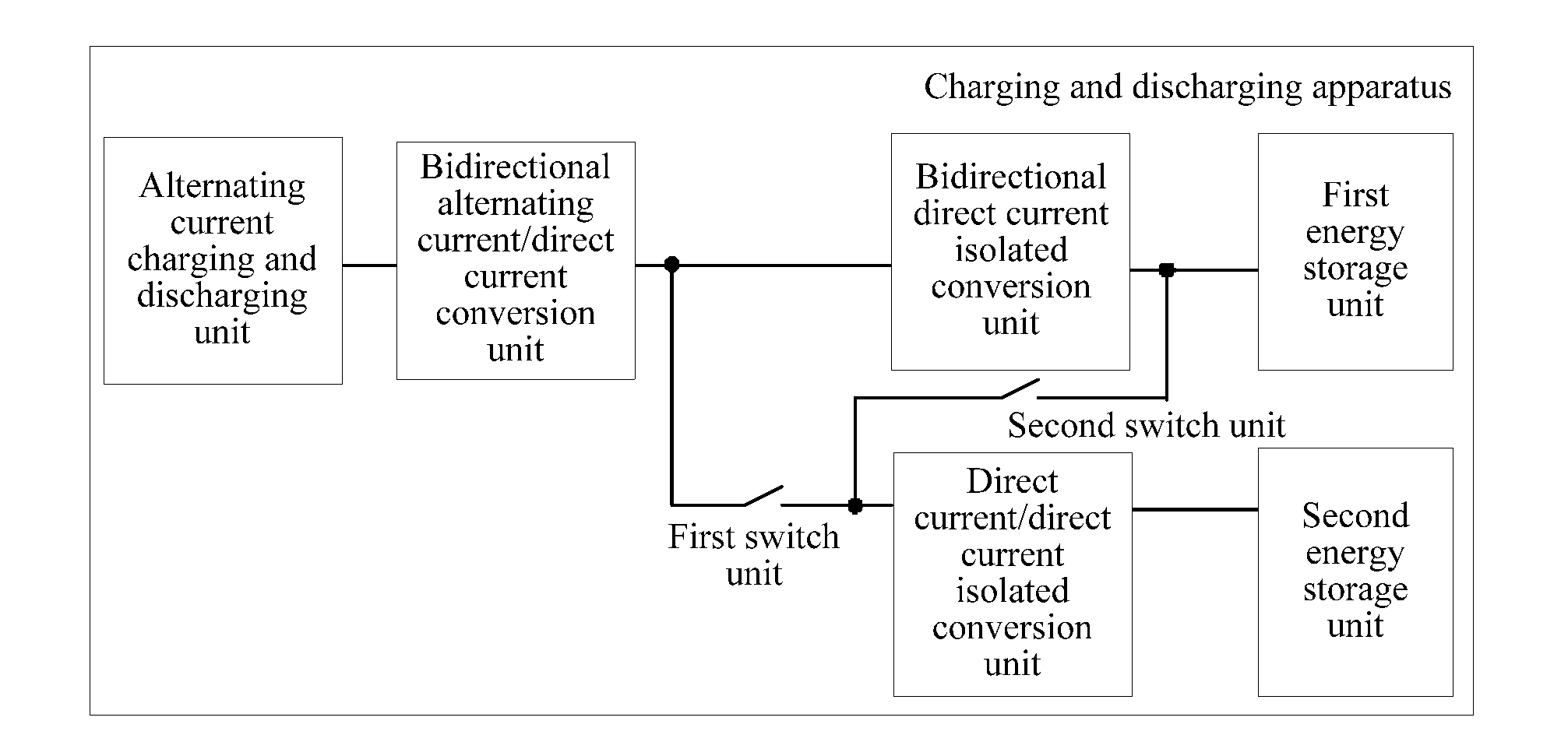
[0004] FIG. 1 is a schematic structural diagram of a charging and discharging apparatus in the prior art. As shown in FIG. 1, an on-board inverter includes an alternating current/direct current conversion unit and a direct current/direct current isolated conversion unit. A first end of the alternating current/direct current conversion unit is connected to an alternating current charging and discharging socket, a second end of the alternating current/direct current conversion unit is connected to a first end of the direct current/direct current isolated conversion unit, and a second end of the direct current/direct current isolated conversion unit is connected to a high-voltage power battery. An on-board charger includes an alternating current/direct current conversion unit and a direct current/direct current isolated conversion unit. Similarly, a first end of the alternating current/direct current conversion unit is connected to the alternating current charging and discharging socket, a second end of the alternating current/direct current conversion unit is connected to a first end of the direct current/direct current isolated conversion unit, and a second end of the direct current/direct current isolated conversion unit is connected to the high-voltage power battery. An on-board DC/DC includes a direct current/direct current boost conversion unit and a direct current/direct current isolated conversion unit. A first end of the direct current/direct current boost conversion unit is connected to the high-voltage power battery, the second end of the direct current/direct current boost conversion unit is connected to a first end of the direct current/direct current isolated conversion unit, and a second end of the direct current/direct current isolated conversion unit is connected to a low-voltage lead-acid battery.
[0005] However, in the prior art, a charging and discharging apparatus includes a relatively large quantity of units, causing a problem that the charging and discharging apparatus and a device such as an electric vehicle in which the apparatus is located are relatively heavy in weight.
SUMMARY
[0006] Embodiments of the present invention provide a charging and discharging apparatus, to reduce a weight of the charging and discharging apparatus and a weight of a device in which the charging and discharging apparatus is located.
[0007] An embodiment of the present invention provides a charging and discharging apparatus, including an alternating current charging and discharging unit, a bidirectional alternating current/direct current conversion unit, a bidirectional direct current/direct current isolated conversion unit, and a first energy storage unit that are sequentially connected in series. The charging and discharging apparatus further includes at least one switch unit, a direct current/direct current isolated conversion unit, and a second energy storage unit. A first end of each switch unit is connected to the bidirectional direct current/direct current isolated conversion unit, a second end of each switch unit is connected to a first end of the direct current/direct current isolated conversion unit, and a second end of the direct current/direct current isolated conversion unit is connected to the second energy storage unit.
[0008] Each switch unit is in an off state when the first energy storage unit is charged by using the alternating current charging and discharging unit or the first energy storage unit charges a to-be-charged device by using the alternating current charging and discharging unit, and one of the at least one switch unit is in an on state when the first energy storage unit charges the second energy storage unit.
[0009] The bidirectional alternating current/direct current conversion unit, the bidirectional direct current/direct current isolated conversion unit, and the direct current/direct current isolated conversion unit in the charging and discharging apparatus replace an alternating current/direct current conversion unit and a direct current/direct current isolated conversion unit included in an on-board inverter, an alternating current/direct current conversion unit and a direct current/direct current isolated conversion unit included in an on-board charger and a direct current/direct current boost conversion unit and a direct current/direct current isolated conversion unit included in an on-board DC/DC in the prior art. Therefore, the charging and discharging apparatus implements functions of the on-board inverter, the on-board charger, and the on-board DC/DC in the prior art, and compared with the prior art, the charging and discharging apparatus includes fewer units, thereby reducing a weight of the charging and discharging apparatus and a weight of a device in which the apparatus is located.
[0010] Optionally, the at least one switch unit is a first switch unit, a first end of the first switch unit is connected to a first end of the bidirectional direct current/direct current isolated conversion unit, a second end of the first switch unit is connected to the first end of the direct current/direct current isolated conversion unit, and the first end of the bidirectional direct current/direct current isolated conversion unit is an end connected to the bidirectional alternating current/direct current conversion unit.
[0011] The first switch unit is in an on state when a voltage value of the first energy storage unit is less than a voltage threshold, to enable the first energy storage unit to charge the second energy storage unit.
[0012] In this case, the first energy storage unit outputs a high-voltage direct current, and the high-voltage direct current flows to the bidirectional direct current/direct current isolated conversion unit. The bidirectional direct current/direct current isolated conversion unit may perform voltage conversion on the high-voltage direct current and output the converted direct current to the direct current/direct current isolated conversion unit. Further, the direct current/direct current isolated conversion unit may implement voltage step down and output the direct current on which voltage adjustment has been performed to the second energy storage unit.
[0013] Optionally, the at least one switch unit is a second switch unit, a first end of the second switch unit is connected to a second end of the bidirectional direct current/direct current isolated conversion unit, a second end of the second switch unit is connected to the first end of the direct current/direct current isolated conversion unit, and the second end of the bidirectional direct current/direct current isolated conversion unit is an end connected to the first energy storage unit.
[0014] The second switch unit is in an on state when a voltage value of the first energy storage unit is greater than or equal to a voltage threshold, to enable the first energy storage unit to charge the second energy storage unit.
[0015] In this case, the first energy storage unit outputs a high-voltage direct current, and the high-voltage direct current flows to the direct current/direct current isolated conversion unit. The direct current/direct current isolated conversion unit may implement voltage step down and output the direct current on which voltage adjustment has been performed to the second energy storage unit.
[0016] Optionally, the at least one switch unit is a first switch unit and a second switch unit, a first end of the first switch unit is connected to a first end of the bidirectional direct current/direct current isolated conversion unit, a second end of the first switch unit is connected to the first end of the direct current/direct current isolated conversion unit, and the first end of the bidirectional direct current/direct current isolated conversion unit is an end connected to the bidirectional alternating current/direct current conversion unit. A first end of the second switch unit is connected to a second end of the bidirectional direct current/direct current isolated conversion unit, and a second end of the second switch unit is connected to the first end of the direct current/direct current isolated conversion unit.
[0017] The first switch unit is in an on state and the second switch unit is in an off state when a voltage value of the first energy storage unit is less than a voltage threshold, to enable the first energy storage unit to charge the second energy storage unit.
[0018] The first switch unit is in an off state and the second switch unit is in an on state when the voltage value of the first energy storage unit is greater than or equal to the voltage threshold, to enable the first energy storage unit to charge the second energy storage unit.
[0019] When the first switch unit is in an on state and the second switch unit is in an off state, refer to the first optional manner, and details are not described herein again. When the first switch unit is in an off state and the second switch unit is in an on state, refer to the second optional manner, and details are not described herein again.
[0020] Optionally, the bidirectional alternating current/direct current conversion unit is a bridgeless power factor correction PFC circuit.
[0021] Optionally, the bidirectional direct current/direct current isolated conversion unit is a bidirectional resonant conversion circuit.
[0022] Optionally, the direct current/direct current isolated conversion unit is an LLC circuit.
[0023] The embodiments of the present invention provide the charging and discharging apparatus, including the alternating current charging and discharging unit, the bidirectional alternating current/direct current conversion unit, the bidirectional direct current/direct current isolated conversion unit, and the first energy storage unit that are sequentially connected in series. The charging and discharging apparatus further includes the at least one switch unit, the direct current/direct current isolated conversion unit, and the second energy storage unit. The first end of each switch unit is connected to the bidirectional direct current/direct current isolated conversion unit, the second end of each switch unit is connected to the first end of the direct current/direct current isolated conversion unit, and the second end of the direct current/direct current isolated conversion unit is connected to the second energy storage unit. Each switch unit is in an off state when the first energy storage unit is charged by using the alternating current charging and discharging unit or the first energy storage unit charges the to-be-charged device by using the alternating current charging and discharging unit, and one of the at least one switch unit is in an on state when the first energy storage unit charges the second energy storage unit. The charging and discharging apparatus implements the functions of the on-board inverter, the on-board charger, and the on-board DC/DC in the prior art, and compared with the prior art, the charging and discharging apparatus includes fewer units, thereby reducing the weight of the charging and discharging apparatus and the weight of the device in which the apparatus is located.
BRIEF DESCRIPTION OF DRAWINGS
[0024] FIG. 1 is a schematic structural diagram of a charging and discharging apparatus in the prior art;
[0025] FIG. 2 is a schematic structural diagram of a charging and discharging apparatus according to an embodiment of the present invention;
[0026] FIG. 3 is a first schematic diagram of a flow direction of a current according to an embodiment of the present invention;
[0027] FIG. 4 is a second schematic diagram of a flow direction of a current according to an embodiment of the present invention;
[0028] FIG. 5 is a third schematic diagram of a flow direction of a current according to an embodiment of the present invention;
[0029] FIG. 6 is a fourth schematic diagram of a flow direction of a current according to an embodiment of the present invention;
[0030] FIG. 7 is a schematic structural diagram of a charging and discharging apparatus according to another embodiment of the present invention;
[0031] FIG. 8 is a schematic structural diagram of a charging and discharging apparatus according to still another embodiment of the present invention; and
[0032] FIG. 9 is a schematic structural diagram of a charging and discharging apparatus according to yet another embodiment of the present invention.
DESCRIPTION OF EMBODIMENTS
[0033] For a problem that a charging and discharging apparatus in the prior art and a device such as an electric vehicle in which the apparatus is located are relatively heavy in weight due to that the charging and discharging apparatus includes a relatively large quantity of units, embodiments of the present invention provide a charging and discharging apparatus.
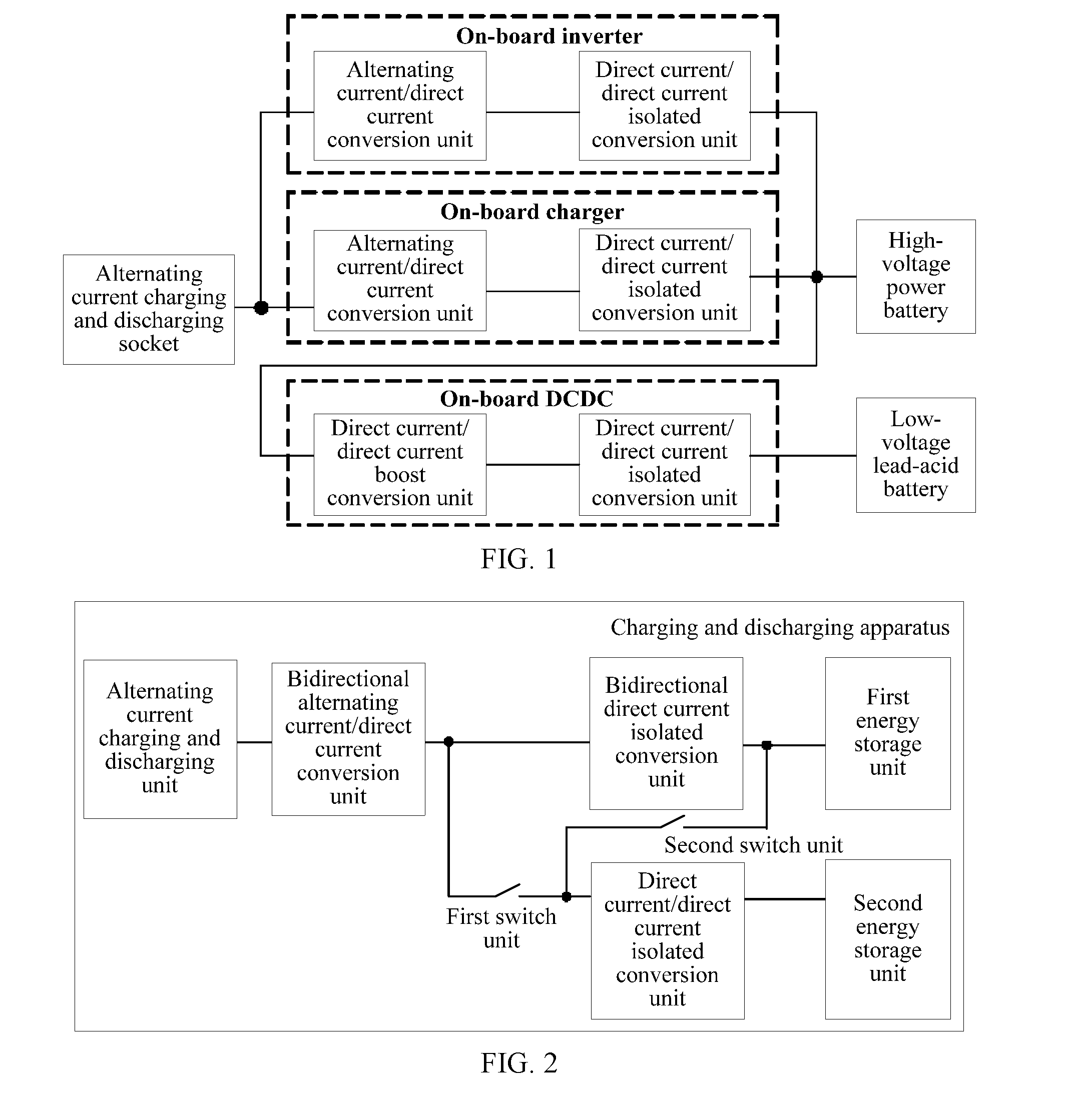
[0034] FIG. 2 is a schematic structural diagram of a charging and discharging apparatus according to an embodiment of the present invention. As shown in FIG. 2, the apparatus includes an alternating current charging and discharging unit, a bidirectional alternating current/direct current conversion unit, a bidirectional direct current/direct current isolated conversion unit, and a first energy storage unit that are sequentially connected in series, and the apparatus further includes at least one switch unit (where an example in which the at least one switch unit is a first switch unit and a second switch unit is used in FIG. 2), a direct current/direct current isolated conversion unit, and a second energy storage unit. A first end of each switch unit is connected to the bidirectional direct current/direct current isolated conversion unit, a second end of each switch unit is connected to a first end of the direct current/direct current isolated conversion unit, and a second end of the direct current/direct current isolated conversion unit is connected to the second energy storage unit.
[0035] Each switch unit is in an off state when the first energy storage unit is charged by using the alternating current charging and discharging unit or the first energy storage unit charges a to-be-charged device by using the alternating current charging and discharging unit, and one of the at least one switch unit is in an on state when the first energy storage unit charges the second energy storage unit.
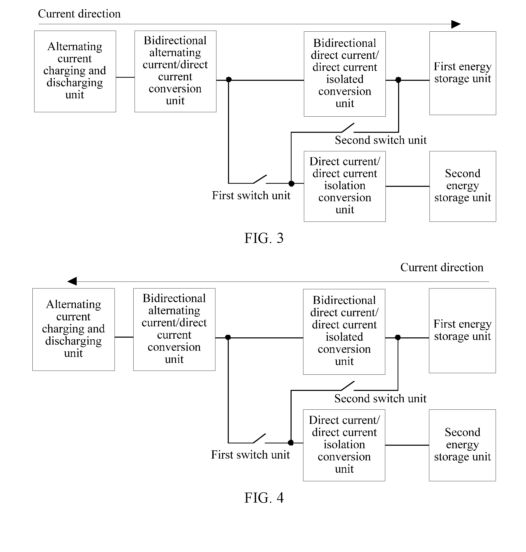
[0036] For example, when the charging and discharging apparatus is applied to an electric vehicle, FIG. 3 is a first schematic diagram of a flow direction of a current according to an embodiment of the present invention. As shown in FIG. 3, an external alternating current of the electric vehicle passes through the alternating current charging and discharging unit, the bidirectional alternating current/direct current conversion unit, and the bidirectional direct current/direct current isolated conversion unit, to charge the first energy storage unit. Optionally, the alternating current charging and discharging unit may be an alternating current charging and discharging socket, an alternating current charging and discharging interface, or the like. The bidirectional alternating current/direct current conversion unit is configured to convert the input alternating current into a direct current and output the direct current into the bidirectional direct current/direct current isolated conversion unit. The bidirectional direct current/direct current isolated conversion unit is configured to perform voltage conversion on the input direct current and output the converted direct current into the first energy storage unit, to charge the first energy storage unit. The first energy storage unit may be a battery, and for example, may be a high-voltage power battery. In conclusion, that the charging and discharging apparatus charges the first energy storage unit is equivalent to a process of charging a high-voltage power battery by using an on-board charger in the prior art.
[0037] A process of charging the to-be-charged device by the charging and discharging apparatus is as follows: FIG. 4 is a second schematic diagram of a flow direction of a current according to an embodiment of the present invention. As shown in FIG. 4, a high-voltage direct current of the first energy storage unit passes through the bidirectional direct current/direct current isolated conversion unit, the bidirectional alternating current/direct current conversion unit, and the alternating current charging and discharging unit, to charge the to-be-charged device connected to the alternating current charging and discharging unit. Optionally, the bidirectional direct current/direct current isolated conversion unit is configured to perform voltage conversion on the high-voltage direct current and output the converted direct current into the bidirectional alternating current/direct current conversion unit. The bidirectional alternating current/direct current conversion unit is configured to convert the input direct current into an alternating current and output the alternating current into the alternating current charging and discharging unit, to charge the to-be-charged device connected to the alternating current charging and discharging unit. In conclusion, that the charging and discharging apparatus charges the to-be-charged device is equivalent to a process of charging a to-be-charged device by using an on-board inverter in the prior art.
[0038] A process of charging the second energy storage unit by the first energy storage unit is as follows: FIG. 5 is a third schematic diagram of a flow direction of a current according to an embodiment of the present invention. As shown in FIG. 5, the first energy storage unit outputs a high-voltage direct current, and the high-voltage direct current flows through the first switch unit to the direct current/direct current isolated conversion unit. The direct current/direct current isolated conversion unit is configured to convert the high-voltage direct current into a low-voltage direct current and output the low-voltage direct current into the second energy storage unit. FIG. 6 a fourth schematic diagram of a flow direction of a current according to an embodiment of the present invention. As shown in FIG. 6, the first energy storage unit outputs a high-voltage direct current, and the high-voltage direct current flows through the second switch unit to the direct current/direct current isolated conversion unit. The direct current/direct current isolated conversion unit is configured to convert the high-voltage direct current into a low-voltage direct current and output the low-voltage direct current into the second energy storage unit. In conclusion, that the first energy storage unit charges the second energy storage unit is equivalent to a function of performing charging by using an on-board DC/DC in the prior art.
[0039] This embodiment of the present invention provides the charging and discharging apparatus. The bidirectional alternating current/direct current conversion unit, the bidirectional direct current/direct current isolated conversion unit, and the direct current/direct current isolated conversion unit in the charging and discharging apparatus replace an alternating current/direct current conversion unit and a direct current/direct current isolated conversion unit included in the on-board inverter, an alternating current/direct current conversion unit included in the on-board charger, and a direct current/direct current isolated conversion unit, a direct current/direct current boost conversion unit, and a direct current/direct current isolated conversion unit included in the on-board DC/DC in the prior art. Compared with the prior art, the charging and discharging apparatus includes fewer units, thereby reducing a weight of the charging and discharging apparatus and a weight of a device in which the apparatus is located.
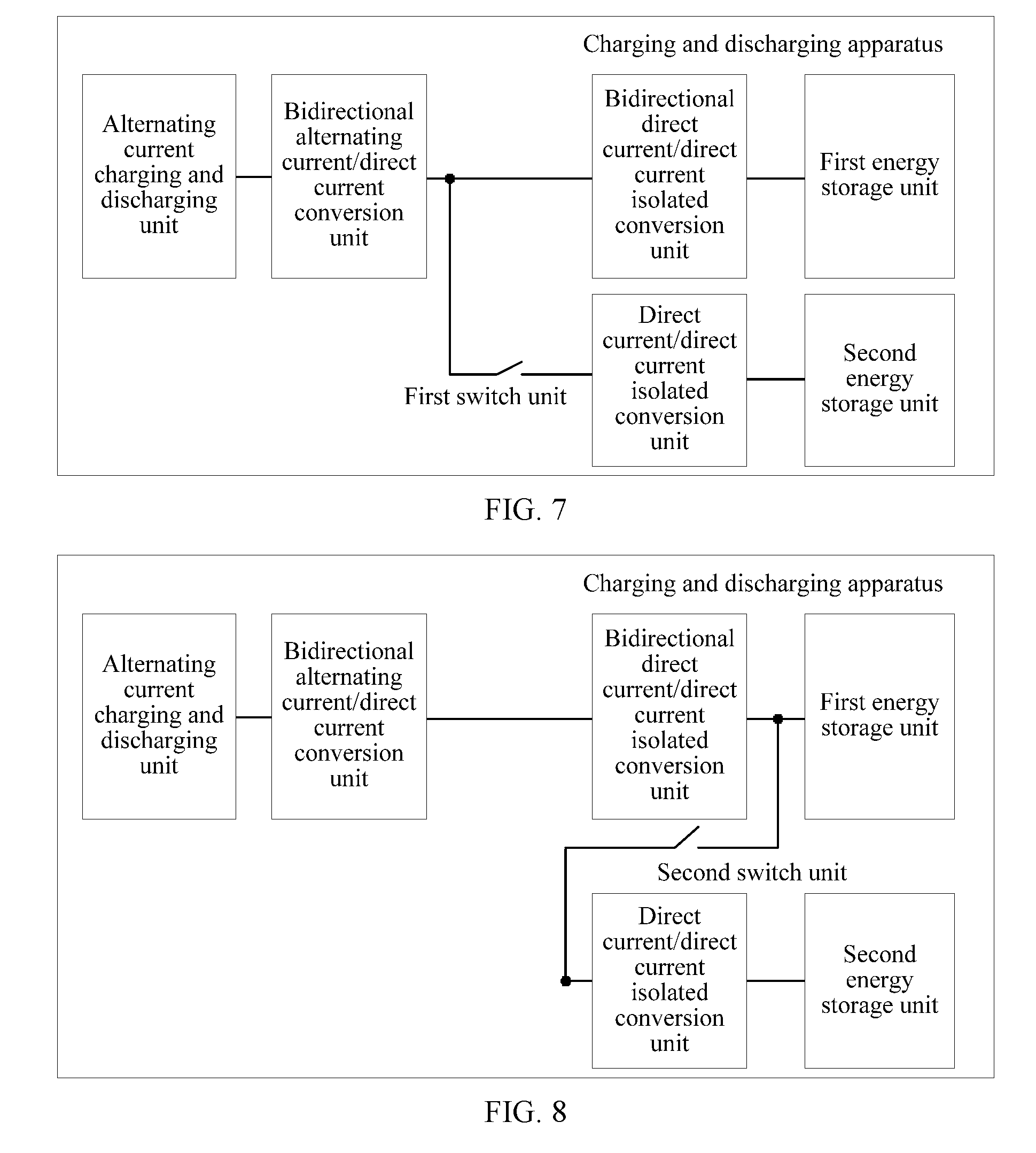
[0040] In a first optional manner, the at least one switch unit is a first switch unit. FIG. 7 is a schematic structural diagram of a charging and discharging apparatus according to another embodiment of the present invention. As shown in FIG. 7, a first end of the first switch unit is connected to a first end of the bidirectional direct current/direct current isolated conversion unit, and a second end of the first switch unit is connected to the first end of the direct current/direct current isolated conversion unit. The first end of the bidirectional direct current/direct current isolated conversion unit is an end connected to the bidirectional alternating current/direct current conversion unit. The first switch unit is in an on state when a voltage value of the first energy storage unit is less than a voltage threshold, to enable the first energy storage unit to charge the second energy storage unit. In this case, the first energy storage unit outputs a high-voltage direct current, and the high-voltage direct current flows to the bidirectional direct current/direct current isolated conversion unit. The bidirectional direct current/direct current isolated conversion unit may perform voltage conversion on the high-voltage direct current and output the converted direct current to the direct current/direct current isolated conversion unit. Further, the direct current/direct current isolated conversion unit may implement voltage step down and output the direct current on which voltage adjustment has been performed to the second energy storage unit. It should be noted that the voltage threshold may be set based on an actual case.
[0041] In a second optional manner, the at least one switch unit is a second switch unit. FIG. 8 is a schematic structural diagram of a charging and discharging apparatus according to still another embodiment of the present invention. As shown in FIG. 8, a first end of a second switch unit is connected to a second end of the bidirectional direct current/direct current isolated conversion unit, and a second end of the second switch unit is connected to the first end of the direct current/direct current isolated conversion unit. The second end of the bidirectional direct current/direct current isolated conversion unit is an end connected to the first energy storage unit. The second switch unit is in an on state when a voltage value of the first energy storage unit is greater than or equal to a voltage threshold, to enable the first energy storage unit to charge the second energy storage unit. In this case, the first energy storage unit outputs a high-voltage direct current, and the high-voltage direct current flows to the direct current/direct current isolated conversion unit. The direct current/direct current isolated conversion unit may implement voltage step down and output the direct current on which voltage adjustment has been performed to the second energy storage unit.
[0042] In a third optional manner, as shown in FIG. 2, the at least one switch unit is a first switch unit and a second switch unit. A first end of the first switch unit is connected to a first end of the bidirectional direct current/direct current isolated conversion unit, and a second end of the first switch unit is connected to the first end of the direct current/direct current isolated conversion unit. The first end of the bidirectional direct current/direct current isolated conversion unit is an end connected to the bidirectional alternating current/direct current conversion unit. A first end of the second switch unit is connected to a second end of the bidirectional direct current/direct current isolated conversion unit, and a second end of the second switch unit is connected to the first end of the direct current/direct current isolated conversion unit. The first switch unit is in an on state and the second switch unit is in an off state when a voltage value of the first energy storage unit is less than a voltage threshold, to enable the first energy storage unit to charge the second energy storage unit. The first switch unit is in an off state and the second switch unit is in an on state when the voltage value of the first energy storage unit is greater than or equal to the voltage threshold, to enable the first energy storage unit to charge the second energy storage unit. It should be noted that in this case, when the first switch unit is in an on state and the second switch unit is in an off state, refer to the first optional manner, and details are not described herein again. When the first switch unit is in an off state and the second switch unit is in an on state, refer to the second optional manner, and details are not described herein again.
[0043] In this embodiment of the present invention, the bidirectional direct current/direct current isolated conversion unit has a voltage adjustment function. Therefore, when the first energy storage unit charges the second energy storage unit, a voltage value of the generated direct current varies depending on whether the high-voltage direct current output by the first energy storage unit passes through or does not pass through the bidirectional direct current/direct current isolated conversion unit, so that a voltage provided for the second energy storage unit also varies.
[0044] Optionally, the bidirectional alternating current/direct current conversion unit is a bridgeless Power Factor Correction (PFC) circuit.
[0045] Optionally, the bidirectional direct current/direct current isolated conversion unit is a bidirectional resonant conversion circuit.
[0046] Optionally, the direct current/direct current isolated conversion unit is an LLC circuit.
[0047] For example, FIG. 9 is a schematic structural diagram of a charging and discharging apparatus according to yet another embodiment of the present invention. As shown in FIG. 9, the apparatus includes an alternating current charging and discharging unit, a bidirectional alternating current/direct current conversion unit, a bidirectional direct current/direct current isolated conversion unit, and a first energy storage unit that are sequentially connected in series, and further includes a first switch unit, a second switch unit, a direct current/direct current isolated conversion unit, and a second energy storage unit. A first end of the first switch unit is connected to a first end of the bidirectional direct current/direct current isolated conversion unit, and a second end of the first switch unit is connected to a first end of the direct current/direct current isolated conversion unit. The first end of the bidirectional direct current/direct current isolated conversion unit is an end connected to the bidirectional alternating current/direct current conversion unit. A first end of the second switch unit is connected to a second end of the bidirectional direct current/direct current isolated conversion unit, and a second end of the second switch unit is connected to the first end of the direct current/direct current isolated conversion unit. The first switch unit is in an on state and the second switch unit is in an off state when a voltage value of the first energy storage unit is less than a voltage threshold, to enable the first energy storage unit to charge the second energy storage unit. The first switch unit is in an off state and the second switch unit is in an on state when the voltage value of the first energy storage unit is greater than or equal to the voltage threshold, to enable the first energy storage unit to charge the second energy storage unit. A second end of the direct current/direct current isolated conversion unit is connected to the second energy storage unit.
[0048] The bidirectional alternating current/direct current conversion unit includes switch tubes S7, S8, S9, S10, S11, and S12, an alternating current power supply Vac, an inductor La, and an inductor Lb. S7 and S8 are connected in series, S9 and S10 are connected in series, and S11 and S12 are connected in series. A series circuit including S7 and S8, a series circuit including S9 and S10, and a series circuit including S11 and S12 are connected in parallel. One end of the alternating current power supply Vac is connected to S11 and the other end is connected to the inductor La. In addition, the alternating current power supply Vac is further connected to the alternating current charging and discharging unit, and the other end of La is connected to the series circuit including S7 and S8. One end of Lb is connected to La and the other end is connected to the series circuit including S9 and S10.
[0049] The bidirectional direct current/direct current isolated conversion unit includes switch tubes S1 to S6 that are connected in series and a capacitor Cp. One end of the capacitor Cp is connected to a positive electrode of a bus, and the other end is connected to a negative electrode of the bus. The bidirectional direct current/direct current isolated conversion unit further includes switch tubes Sr1 to Sr6 that are connected in series and a capacitor Cs1. One end of the capacitor Cs1 is connected to a positive electrode of the first energy storage unit and the other end is connected to a negative electrode of the first energy storage unit. The bidirectional direct current/direct current isolated conversion unit further includes three three-port multi-element resonant cavities and three transformers T1, T2, and T3. A first end of a multi-element resonant cavity 1 is connected between S1 and S2, a second end of the multi-element resonant cavity 1 is connected to the negative electrode of the bus, a third end of the multi-element resonant cavity 1 is connected to a primary-side winding of T1, and a secondary-side winding of T1 is connected between Sr1 and Sr2. Similarly, a first end of a multi-element resonant cavity 2 is connected between S3 and S4, a second end of the multi-element resonant cavity 2 is connected to the negative electrode of the bus, a third end of the multi-element resonant cavity 2 is connected to a primary-side winding of T2, and a secondary-side winding of T2 is connected between Sr3 and Sr4. A first end of a multi-element resonant cavity 3 is connected between S5 and S6, a second end of the multi-element resonant cavity 3 is connected to the negative electrode of the bus, a third end of the multi-element resonant cavity 3 is connected to a primary-side winding of T3, and a secondary-side winding of T3 is connected between Sr5 and Sr6.
[0050] The direct current/direct current isolated conversion unit includes switch tubes Sd1 to Sd4, an inductor Lr, a capacitor Cr, a capacitor Cs2, and a transformer T4. Sd1 and Sd2 are connected in series, one end of Lr is connected between Sd1 and Sd2 and the other end is connected to Cr, the other end of Cr is connected to one end of a primary-side winding of T4, and the other end of the primary-side winding of T4 is connected to Sd2. A first end of a secondary-side winding of T4 is connected to Sd3, a second end is connected to Sd4, and a third end is connected to Cs2.
[0051] The first switch unit includes two switch tubes, and the second switch unit also includes two switch tubes.
[0052] Optionally, the switch tube may be an insulated gate bipolar transistor (Insulated Gate Bipolar Transistor, IGBT for short), a Metal Oxide Semiconductor Field Effect Transistor (MOSFET), or the like.
[0053] This embodiment of the present invention provides the charging and discharging apparatus. The bidirectional alternating current/direct current conversion unit, the bidirectional direct current/direct current isolated conversion unit, and the direct current/direct current isolated conversion unit in the charging and discharging apparatus replace an alternating current/direct current conversion unit and a direct current/direct current isolated conversion unit included in an on-board inverter, an alternating current/direct current conversion unit and a direct current/direct current isolated conversion unit included in an on-board charger and a direct current/direct current boost conversion unit and a direct current/direct current isolated conversion unit included in an on-board DC/DC in the prior art. Compared with the prior art, the charging and discharging apparatus includes fewer units, thereby reducing a weight of the charging and discharging apparatus and a weight of a device in which the apparatus is located.
* * * * *
D00000
D00001
D00002
D00003
D00004
D00005
XML
uspto.report is an independent third-party trademark research tool that is not affiliated, endorsed, or sponsored by the United States Patent and Trademark Office (USPTO) or any other governmental organization. The information provided by uspto.report is based on publicly available data at the time of writing and is intended for informational purposes only.
While we strive to provide accurate and up-to-date information, we do not guarantee the accuracy, completeness, reliability, or suitability of the information displayed on this site. The use of this site is at your own risk. Any reliance you place on such information is therefore strictly at your own risk.
All official trademark data, including owner information, should be verified by visiting the official USPTO website at www.uspto.gov. This site is not intended to replace professional legal advice and should not be used as a substitute for consulting with a legal professional who is knowledgeable about trademark law.