Heat Dissipation Device
CHEN; CHIEN-AN ; et al.
U.S. patent application number 15/936544 was filed with the patent office on 2019-08-29 for heat dissipation device. The applicant listed for this patent is AURAS Technology Co., Ltd.. Invention is credited to CHIEN-AN CHEN, CHIEN-YU CHEN, MU-SHU FAN.
| Application Number | 20190264986 15/936544 |
| Document ID | / |
| Family ID | 65431737 |
| Filed Date | 2019-08-29 |


| United States Patent Application | 20190264986 |
| Kind Code | A1 |
| CHEN; CHIEN-AN ; et al. | August 29, 2019 |
HEAT DISSIPATION DEVICE
Abstract
A heat dissipation device includes a storage structure, plural pipes, plural heat sink fin groups and a vaporization-enhancing structure. The heat sink fin groups are disposed on outer surfaces of the pipes. The storage structure includes a chamber. The storage structure is in thermal contact with a heat source. Each pipe has a channel. A first end of the channel is in fluid communication with the chamber. A working medium is filled in the chamber and the channels of the pipes. The vaporization-enhancing structure is disposed within the chamber and in thermal contact with at least a portion of the working medium. After the vaporization-enhancing structure receives heat energy from the heat source, the heat energy is transferred to the working medium. The vaporization-enhancing structure facilitates liquid-gas transformation of the working medium. Consequently, the working medium moves toward a second end of the first channel.
| Inventors: | CHEN; CHIEN-AN; (New Taipei City, TW) ; FAN; MU-SHU; (New Taipei City, TW) ; CHEN; CHIEN-YU; (New Taipei City, TW) | ||||||||||
| Applicant: |
|
||||||||||
|---|---|---|---|---|---|---|---|---|---|---|---|
| Family ID: | 65431737 | ||||||||||
| Appl. No.: | 15/936544 | ||||||||||
| Filed: | March 27, 2018 |
| Current U.S. Class: | 1/1 |
| Current CPC Class: | F28F 1/24 20130101; F28D 1/0476 20130101; H05K 7/20309 20130101; F28D 1/0233 20130101; F28F 1/04 20130101; F28F 2009/0292 20130101; F28F 1/40 20130101; F28F 2215/02 20130101; F28D 1/05366 20130101; H01L 23/427 20130101; F28D 1/0226 20130101; F28D 15/0266 20130101; H05K 7/2029 20130101; H05K 7/20318 20130101; F28D 2021/0028 20130101; H01L 23/3672 20130101; F28D 15/0275 20130101; F28D 2021/0064 20130101 |
| International Class: | F28D 15/02 20060101 F28D015/02; F28D 1/02 20060101 F28D001/02; F28F 1/04 20060101 F28F001/04; F28F 1/40 20060101 F28F001/40 |
Foreign Application Data
| Date | Code | Application Number |
|---|---|---|
| Feb 27, 2018 | TW | 107106603 |
Claims
1. A heat dissipation device, comprising: a first storage structure comprising a first chamber, wherein the first storage structure is in thermal contact with a heat source; at least one first pipe, wherein an inner portion of each first pipe has a first channel, a first end of the first channel is in fluid communication with the first chamber, and a working medium is filled in the first chamber and the first channel; at least one heat sink fin group disposed on an outer surface of the at least one first pipe; and a vaporization-enhancing structure disposed within the first chamber and in thermal contact with the first storage structure and at least a portion of the working medium, wherein after the vaporization-enhancing structure receives heat energy from the heat source, the heat energy is transferred to the working medium, wherein the vaporization-enhancing structure facilitates liquid-gas transformation of the working medium, so that the working medium moves in a direction toward a second end of the first channel.
2. The heat dissipation device according to claim 1, wherein the at least one first pipe comprises plural first pipes, and the at least one heat sink fin group comprises plural heat sink fin groups, wherein each of the plural first pipes is arranged between two adjacent ones of the plural heat sink fin groups.
3. The heat dissipation device according to claim 1, wherein the vaporization-enhancing structure comprises plural skived fins.
4. The heat dissipation device according to claim 1, wherein the first storage structure further comprises a first plate, a second plate and plural lateral plates, wherein the plural lateral plates are connected between the first plate and the second plate, and the first chamber is defined by the first plate, the second plate and the plural lateral plates collaboratively.
5. The heat dissipation device according to claim 4, wherein the second plate comprises at least one opening, and the opening is in communication with the first end of the first channel.
6. The heat dissipation device according to claim 1, wherein the heat dissipation device further comprises a second storage structure, and the second storage structure comprises a second chamber, wherein the second chamber is in fluid communication with the second end of the first channel, and a sealed space is defined by the first chamber, the second chamber and the at least one first channel.
7. The heat dissipation device according to claim 6, wherein the heat dissipation device further comprises a heat dissipation element, wherein the heat dissipation element is disposed on an outer surface of the second storage structure.
8. The heat dissipation device according to claim 6, wherein the heat dissipation device further comprises a liquefaction-enhancing structure, wherein the liquefaction-enhancing structure is disposed within the second chamber and in thermal contact with the second storage structure and at least a portion of the working medium, wherein the liquefaction-enhancing structure facilitates gas-liquid transformation of the working medium, so that the working medium moves in a direction toward the first end of the first channel.
9. The heat dissipation device according to claim 8, wherein the liquefaction-enhancing structure comprises plural skived fins.
10. The heat dissipation device according to claim 1, wherein the second end of the first channel is closed.
11. The heat dissipation device according to claim 1, wherein the first end and the second end of the at least one first pipe are connected with the first storage structure.
12. The heat dissipation device according to claim 1, wherein an inner portion of the at least one first pipe is equipped with a liquefaction-enhancing structure, wherein the liquefaction-enhancing structure facilitates gas-liquid transformation of the working medium, so that the working medium moves in a direction toward the first end of the first channel.
13. The heat dissipation device according to claim 12, wherein the liquefaction-enhancing structure comprises plural capillary structures or recesses, which are formed on an inner surface of the at least one first pipe and disposed within the first channel.
14. The heat dissipation device according to claim 1, wherein the heat dissipation device further comprises: a third storage structure comprising a third chamber, wherein the third storage structure is in thermal contact with the heat source or an additional heat source; at least one second pipe, wherein an inner portion of each second pipe has a second channel, a first end of the second channel is in fluid communication with the third chamber, and an additional working medium is filled in the third chamber and the second channel; at least one additional heat sink fin group disposed on an outer surface of the at least one second pipe; and an additional vaporization-enhancing structure disposed within the third chamber and in thermal contact with the third storage structure and at least a portion of the additional working medium, wherein after the vaporization-enhancing structure receives heat energy from the heat source or the additional heat source, the heat energy is transferred to the additional working medium, wherein the additional vaporization-enhancing structure facilitates liquid-gas transformation of the additional working medium, so that the additional working medium moves in a direction toward a second end of the second channel.
15. The heat dissipation device according to claim 14, wherein at least one of the first storage structure and the at least one first pipe and at least one of the third storage structure and the at least one second pipe are directly connected with each other and linked with each other, or at least one of the first storage structure and the at least one first pipe and at least one of the third storage structure and the at least one second pipe are linked with each other through an intermediate coupling mechanism.
16. The heat dissipation device according to claim 14, wherein the first pipe is a vertical pipe, and the second pipe is a horizontal pipe.
17. The heat dissipation device according to claim 14, wherein the additional vaporization-enhancing structure comprises plural skived fins.
Description
FIELD OF THE INVENTION
[0001] The present invention relates to a heat dissipation device, and more particularly to a heat dissipation device for dissipating heat through two phase changes.
BACKGROUND OF THE INVENTION
[0002] With increasing development of computers and various electronic devices, people in the modern societies are used to using the computers and the electronic devices for a long time. During operations of the computers and the electronic devices, a great deal of heat is generated. If the heat cannot be effectively dissipated away, some drawbacks occur.
[0003] For solving the above drawbacks, various heat dissipation mechanisms such as airflow convection mechanisms (e.g., through fans), water cooling mechanisms or thermosyphon mechanisms are widely used. For example, thermosiphon is heat dissipation method for allowing a working medium (e.g., water) to flow along a circular loop without the need of using a pump to push the working medium. Nowadays, many literatures about the researches and technologies of the thermosiphon mechanisms have been disclosed. For example, US Patent Publication No. 20100315781 discloses a thermosyphon heat exchanger. Moreover, a water cooling radiator is one of the widely-used heat exchanger in the associated application fields. The water cooling radiator cooperates with a fan to cool down the high temperature liquid or condense the vaporized stem into liquid. Consequently, the liquid flows along a circular loop without any pump. In other words, the processes of vaporizing and condensing the liquid are sufficient for circulating the liquid. The principles of the thermosiphon and the operations of the water cooling radiator are well known to those skilled in the art, and are not redundantly described herein.
[0004] However, in some usage situations, the thermosyphon heat exchanger is unable to effectively remove the heat from the computer or the electronic device because the circulating efficacy of the working liquid within the thermosyphon heat exchanger is unsatisfied. The applicant found that the vaporizing efficiency and the liquefying efficiency of the working liquid in the heat dissipation device are important factors influencing the circulation of the working medium. Therefore, it is important to enhance the circulation of the working medium in the heat dissipation device.
SUMMARY OF THE INVENTION
[0005] For solving the drawbacks of the conventional technologies, the present invention provides a heat dissipation device with a vaporization-enhancing structure for increasing the thermal contact area and enhancing the efficiency of vaporizing the working medium. Consequently, the circulation of the working medium in the heat dissipation device is enhanced, and the overall heat dissipation performance is effectively enhanced.
[0006] In accordance with an aspect of the present invention, there is provided a heat dissipation device. The heat dissipation device includes a first storage structure, at least one first pipe, at least one heat sink fin group and a vaporization-enhancing structure. The first storage structure includes a first chamber. The first storage structure is in thermal contact with a heat source. An inner portion of each first pipe has a first channel. A first end of the first channel is in fluid communication with the first chamber. A working medium is filled in the first chamber and the first channel. The at least one heat sink fin group is disposed on an outer surface of the at least one first pipe. The vaporization-enhancing structure is disposed within the first chamber and in thermal contact with the first storage structure and at least a portion of the working medium. After the vaporization-enhancing structure receives heat energy from the heat source, the heat energy is transferred to the working medium. The vaporization-enhancing structure facilitates liquid-gas transformation of the working medium, so that the working medium moves in a direction toward a second end of the first channel.
[0007] In an embodiment, the at least one first pipe includes plural first pipes, and the at least one heat sink fin group includes plural heat sink fin groups. Each of the plural first pipes is arranged between two adjacent ones of the plural heat sink fin groups.
[0008] In an embodiment, the vaporization-enhancing structure includes plural skived fins.
[0009] In an embodiment, the first storage structure further includes a first plate, a second plate and plural lateral plates. The plural lateral plates are connected between the first plate and the second plate. The first chamber is defined by the first plate, the second plate and the plural lateral plates collaboratively.
[0010] In an embodiment, the second plate includes at least one opening, and the opening is in communication with the first end of the first channel.
[0011] In an embodiment, the heat dissipation device further includes a second storage structure, and the second storage structure includes a second chamber. The second chamber is in fluid communication with the second end of the first channel. Moreover, a sealed space is defined by the first chamber, the second chamber and the at least one first channel.
[0012] In an embodiment, the heat dissipation device further includes a heat dissipation element. The heat dissipation element is disposed on an outer surface of the second storage structure.
[0013] In an embodiment, the heat dissipation device further includes a liquefaction-enhancing structure. The liquefaction-enhancing structure is disposed within the second chamber and in thermal contact with the second storage structure and at least a portion of the working medium. The liquefaction-enhancing structure facilitates gas-liquid transformation of the working medium, so that the working medium moves in a direction toward the first end of the first channel.
[0014] In an embodiment, the liquefaction-enhancing structure includes plural skived fins.
[0015] In an embodiment, the second end of the first channel is closed.
[0016] In an embodiment, the first end and the second end of the at least one first pipe are connected with the first storage structure.
[0017] In an embodiment, an inner portion of the at least one first pipe is equipped with a liquefaction-enhancing structure. The liquefaction-enhancing structure facilitates gas-liquid transformation of the working medium, so that the working medium moves in a direction toward the first end of the first channel.
[0018] In an embodiment, the liquefaction-enhancing structure includes plural capillary structures or recesses, which are formed on an inner surface of the at least one first pipe and disposed within the first channel.
[0019] In an embodiment, the heat dissipation device further includes a third storage structure, at least one second pipe, at least one additional heat sink fin group and an additional vaporization-enhancing structure. The third storage structure includes a third chamber. The third storage structure is in thermal contact with the heat source or an additional heat source. An inner portion of each second pipe has a second channel. A first end of the second channel is in fluid communication with the third chamber. An additional working medium is filled in the third chamber and the second channel. The at least one additional heat sink fin group is disposed on an outer surface of the at least one second pipe. The additional vaporization-enhancing structure is disposed within the third chamber and in thermal contact with the third storage structure and at least a portion of the additional working medium. After the vaporization-enhancing structure receives heat energy from the heat source or the additional heat source, the heat energy is transferred to the additional working medium. The additional vaporization-enhancing structure facilitates liquid-gas transformation of the additional working medium, so that the additional working medium moves in a direction toward a second end of the second channel.
[0020] In an embodiment, at least one of the first storage structure and the at least one first pipe and at least one of the third storage structure and the at least one second pipe are directly connected with each other and linked with each other, or at least one of the first storage structure and the at least one first pipe and at least one of the third storage structure and the at least one second pipe are linked with each other through an intermediate coupling mechanism.
[0021] In an embodiment, the first pipe is a vertical pipe, and the second pipe is a horizontal pipe.
[0022] In an embodiment, the additional vaporization-enhancing structure includes plural skived fins.
[0023] From the above descriptions, the heat dissipation device of the present invention is equipped with the vaporization-enhancing structure to increase the thermal contact area and enhance the vaporizing efficiency of the working medium. Consequently, the circulating efficacy of the working medium within the heat dissipation device is enhanced, and the overall heat dissipation performance of the heat dissipation device is increased. In an embodiment, the vaporization-enhancing structure comprises plural skived fins. Since the skived fins have the advantages of high density fins, the thermal contact area between the vaporization-enhancing structure and the liquid working medium is increased. Since the vaporizing speed of the liquid working medium is increased, the circulating efficacy of the liquid working medium within the heat dissipation device is further enhanced and the overall heat dissipation performance of the heat dissipation device is increased. Moreover, since the vaporization-enhancing structure is composed of the plural skived fins, the fabricating cost is reduced.
[0024] The above objects and advantages of the present invention will become more readily apparent to those ordinarily skilled in the art after reviewing the following detailed description and accompanying drawings, in which:
BRIEF DESCRIPTION OF THE DRAWINGS
[0025] FIG. 1 is a schematic perspective view illustrating the outer appearance of a heat dissipation device according to a first embodiment of the present invention;
[0026] FIG. 2 is a schematic exploded view illustrating a portion of the heat dissipation device as shown in FIG. 1;
[0027] FIG. 3 is a schematic cross-sectional view illustrating a portion of the heat dissipation device as shown in FIG. 1;
[0028] FIG. 4 is a schematic cross-sectional view illustrating a portion of a heat dissipation device according to a second embodiment of the present invention;
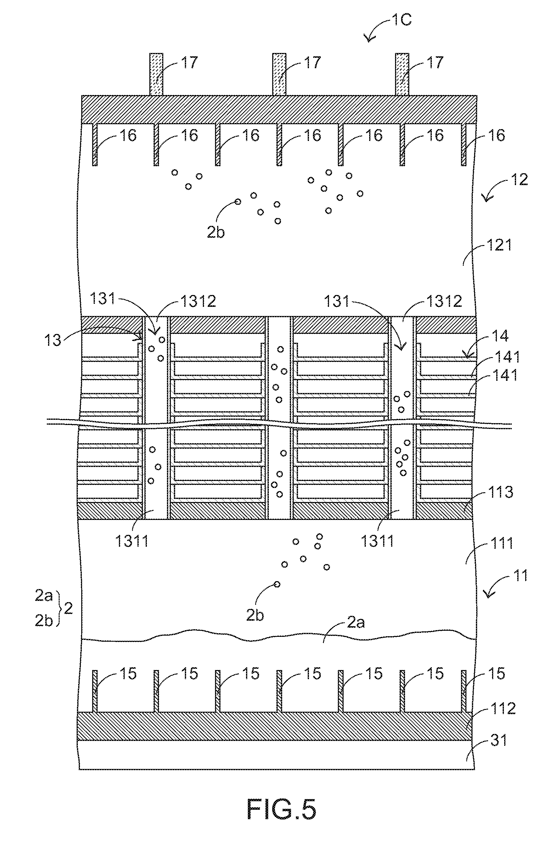
[0029] FIG. 5 is a schematic cross-sectional view illustrating a portion of a heat dissipation device according to a third embodiment of the present invention;
[0030] FIG. 6 is a schematic cross-sectional view illustrating a portion of a heat dissipation device according to a fourth embodiment of the present invention;
[0031] FIG. 7 is a schematic cross-sectional view illustrating a portion of a heat dissipation device according to a fifth embodiment of the present invention;
[0032] FIG. 8 is a schematic cross-sectional view illustrating a portion of a heat dissipation device according to a sixth embodiment of the present invention; and
[0033] FIG. 9 is a schematic cross-sectional view illustrating a portion of a heat dissipation device according to a seventh embodiment of the present invention.
DETAILED DESCRIPTION OF THE PREFERRED EMBODIMENT
[0034] In this context, the term "thermal contact" is the contact via thermal conduction. In accordance with the present invention, the thermal contact has two types, including a direct contact mechanism and an indirect contact mechanism. In some embodiments, the thermal contact also includes the contact between two components that are close to each other but not contacted with each other. If two components are directly attached on each other, these two components are in direct contact. If a thermally conductive medium (e.g., thermal paste) is arranged between two components, these two components are in indirect contact. The examples are presented herein for purpose of illustration and description only.
[0035] Please refer to FIGS. 1, 2 and 3. FIG. 1 is a schematic perspective view illustrating the outer appearance of a heat dissipation device according to a first embodiment of the present invention. FIG. 2 is a schematic exploded view illustrating a portion of the heat dissipation device as shown in FIG. 1. FIG. 3 is a schematic cross-sectional view illustrating a portion of the heat dissipation device as shown in FIG. 1. The heat dissipation device 1A comprises a first storage structure 11, a second storage structure 12, plural first pipes 13, plural heat sink fin groups 14 and a vaporization-enhancing structure 15. The second storage structure 12 is located over the first storage structure 11. The first storage structure 11 comprises a first chamber 111. The second storage structure 12 comprises a second chamber 121. An inner portion of each first pipe 13 has a first channel 131. A first end 1311 of the first channel 131 is in fluid communication with the first chamber 111. A second end 1312 of the first channel 131 is in fluid communication with the second chamber 121. Moreover, a sealed space is defined by the first chamber 111 of the first storage structure 11, the second chamber 121 of the second storage structure 12 and the first channels 131 of the plural first pipes 13. A working medium 2 is filled in the sealed space. The heat sink fin groups 14 are disposed on outer surfaces of the first pipes 13. After the heat sink fin groups 14 receive heat energy from the first pipes 13, the heat energy is removed by the ambient airflow. The vaporization-enhancing structure 15 is disposed within the first chamber 111. Moreover, the vaporization-enhancing structure 15 is in thermal contact with the first storage structure 11 and at least a portion of the working medium 2. For example, the vaporization-enhancing structure 15 is immersed in at least a portion of the working medium 2. The vaporization-enhancing structure 15 is used for increasing the efficiency of vaporizing the working medium 2. The operations of the vaporization-enhancing structure 15 will be described herein.
[0036] In an embodiment, each first pipe 13 is arranged between two adjacent heat sink fin groups 14. Each heat sink fin group 14 comprises heat sink fins 141. These heat sink fins 141 are substantially parallel with each other and spaced apart from each other in the vertical direction, and arranged on the outer surfaces of the first pipes 13. In an embodiment, the first storage structure 11 further comprises a first plate 112, a second plate 113 and plural lateral plates 114. The plural lateral plates 114 are connected between the first plate 112 and the second plate 113. The first chamber 111 is defined by the first plate 112, the second plate 113 and the plural lateral plates 114 collaboratively. The vaporization-enhancing structure 15 comprises plural skived fins. The vaporization-enhancing structure 15 is disposed on the first plate 112. The second plate 113 comprises plural openings 1131. The plural openings 1131 are in communication with the first ends 1311 of the first channels 131 of the first pipes 13. The structure of the second storage structure 12 is similar to that of the first storage structure 11, and is not redundantly described herein.
[0037] The above examples are presented herein for purpose of illustration and description only. The constituents of the heat sink fin groups 14, the arrangements of the heat sink fins 141, the constituents of the first storage structure 11, the constituents of the second storage structure 12 and the relationships between the first storage structure 11, the second storage structure 12 and the first pipes 13, the example of the vaporization-enhancing structure 15 and the relative positions between the vaporization-enhancing structure 15 and the first chamber 111 of the first storage structure 11 are not restricted. That is, numerous modifications and alterations may be made according to the practical requirements.
[0038] The principles of removing heat energy by the heat dissipation device 1A will be described as follows. When the first plate 112 of the first storage structure 11 is in thermal contact with an underlying heat source 31, the heat energy of the heat source 31 is transferred to the liquid working medium 2a through the first plate 112 and the overlying vaporization-enhancing structure 15. The liquid working medium 2a is disposed within the first chamber 111 and in thermal contact with the first plate 112 and the vaporization-enhancing structure 15. After the liquid working medium 2a absorbs sufficient heat energy, the liquid working medium 2a is vaporized. Consequently, the liquid working medium 2a is transformed into the gaseous working medium 2b. That is, the liquid-gas transformation occurs. Then, the gaseous working medium 2b enters the first channels 131 through the first ends 1311 of the first channels 131 of the first pipes 13 and moves in the direction toward the second ends 1312 of the first channels 131. The heat energy of the gaseous working medium 2b in the first channels 131 is externally transferred to the heat sink fin groups 14, which are disposed on the outer surfaces of the first pipes 13. Since the gaseous working medium 2b releases heat energy, the gaseous working medium 2b is condensed and liquefied. The gaseous working medium 2b is transformed into the liquid working medium 2a again. The liquid working medium 2a flows back into the first chamber 111 of the first storage structure 11 through the first ends 1311 of the first channels 131 of the first pipes 13 and accumulates in the first chamber 111.
[0039] Through the working loop of the two phase changes, the heat energy generated by the heat source 31 can be quickly dissipated away by the heat dissipation device 1A. As mentioned above, the vaporization-enhancing structure 15 comprises the plural skived fins. Since the skived fins have the advantages of high density fins, the thermal contact area between the vaporization-enhancing structure 15 and the liquid working medium 2a is increased. That is, the heat transfer area is increased. Moreover, since the vaporizing speed of the liquid working medium 2a is increased, the circulating efficacy of the working medium 2 within the heat dissipation device 1A is enhanced and the overall heat dissipation performance of the heat dissipation device 1A is increased. Moreover, since the vaporization-enhancing structure 15 is composed of the plural skived fins, the fabricating cost is reduced.
[0040] FIG. 4 is a schematic cross-sectional view illustrating a portion of a heat dissipation device according to a second embodiment of the present invention. The structures of the components of the heat dissipation device 1B which are similar to those of the heat dissipation device of the first embodiment are not redundantly described herein. In comparison with the first embodiment, the heat dissipation device 1B of this embodiment further comprises a liquefaction-enhancing structure 16. The liquefaction-enhancing structure 16 is disposed within the second chamber 121 and in thermal contact with the second storage structure 12 and at least a portion of the gaseous working medium 2b. The liquefaction-enhancing structure 16 is used for enhancing the efficiency of liquefying the gaseous working medium 2b during the gas-liquid transformation process. In an embodiment, the liquefaction-enhancing structure 16 comprises plural skived fins.
[0041] Similarly, after the gaseous working medium 2b in the first channels 131 of the first pipes 13 releases heat energy, the gaseous working medium 2b is liquefied into the liquid working medium 2a. The liquid working medium 2a flows back into the first chamber 111. However, a portion of the gaseous working medium 2b in the first channels 131 of the first pipes 13 is possibly not liquefied and enters the second chamber 121 through the second ends 1312 of the first channels 131.
[0042] In this embodiment, the liquefaction-enhancing structure 16 is disposed within the second chamber 121, and the liquefaction-enhancing structure 16 is composed of plural skived fins. As mentioned above, the skived fins have the advantages of high density fins, and thus the thermal contact area between the liquefaction-enhancing structure 16 and the gaseous working medium 2b is increased. Since the heat transfer area is increased, the speed of liquefying the gaseous working medium 2b is increased. The liquid working medium 2a flows back into the first chamber 111 of the first storage structure 11 through the first ends 1311 of the first channels 131 of the first pipes 13 and accumulates in the first chamber 111. In other words, the use of the liquefaction-enhancing structure 16 also enhances the circulating efficacy of the working medium 2 within the heat dissipation device 1B and increases the overall heat dissipation performance of the heat dissipation device 1B. It is noted that the example of the liquefaction-enhancing structure 16 is not restricted. That is, any other structure capable of increasing the thermal contact area to increase the speed of liquefying the gaseous working medium 2b can be used as the liquefaction-enhancing structure 16.
[0043] FIG. 5 is a schematic cross-sectional view illustrating a portion of a heat dissipation device according to a third embodiment of the present invention. The structures of the components of the heat dissipation device 1C which are similar to those of the first embodiment and the second embodiment are not redundantly described herein. In comparison with the first embodiment and the second embodiment, the heat dissipation device 1C of this embodiment further comprises a heat dissipation element 17. The heat dissipation element 17 is disposed on the outer surface of the second storage structure 12. The heat dissipation element 17 can facilitate removing the heat energy from the second storage structure 12 to the surroundings. Consequently, the gaseous working medium 2b in the second storage structure 12 can be liquefied into the liquid working medium 2a more quickly. The liquid working medium 2a flows back into the first chamber 111 of the first storage structure 11 through the first ends 1311 of the first channels 131 of the first pipes 13 and accumulates in the first chamber 111. In an embodiment, the heat dissipation element 17 comprises plural fins for receiving the heat energy from the second storage structure 12. It is noted that the example of the heat dissipation element 17 is not restricted.
[0044] FIG. 6 is a schematic cross-sectional view illustrating a portion of a heat dissipation device according to a fourth embodiment of the present invention. The structures of the components of the heat dissipation device 1D which are similar to those of the first embodiment, the second embodiment and the third embodiment are not redundantly described herein. In comparison with the first embodiment, the second embodiment and the third embodiment, each first pipe 13 of the heat dissipation device 1D of this embodiment further comprises a liquefaction-enhancing structure 18. The liquefaction-enhancing structure 18 is formed on an inner surface of the first pipe 13 and disposed within the first channel 131. The liquefaction-enhancing structure 18 is used for increasing the thermal contact area between the first channel 131 and the gaseous working medium 2b. Consequently, the efficiency of liquefying the gaseous working medium 2b in the first channel 131 is enhanced. Preferably but not exclusively, the liquefaction-enhancing structure 18 comprises plural capillary structures or recesses.
[0045] FIG. 7 is a schematic cross-sectional view illustrating a portion of a heat dissipation device according to a fifth embodiment of the present invention. The structures of the components of the heat dissipation device lE which are similar to those of the heat dissipation device of the first embodiment are not redundantly described herein. In comparison with the first embodiment, the heat dissipation device lE of this embodiment is not equipped with the second storage structure 12 and the second end 1312 of the first channel 131 of each first pipe 13 is closed. The principles of using the heat dissipation device lE to remove heat energy are similar to those of the first embodiment, and are not redundantly described herein.
[0046] FIG. 8 is a schematic cross-sectional view illustrating a portion of a heat dissipation device according to a sixth embodiment of the present invention. The structures of the components of the heat dissipation device 1F which are similar to those of the heat dissipation device of the fifth embodiment are not redundantly described herein. In comparison with the fifth embodiment, the first pipes 13F are distinguished. In this embodiment, two ends of each first pipe 13F are connected with the first storage structure 11. In other words, the first end 1311 and the second end 1312 of the first channel 131 of each first pipe 13F are in communication with the first chamber 111 of the first storage structure 11. The principles of using the heat dissipation device 1F to remove heat energy are similar to those of the first embodiment, and are not redundantly described herein.
[0047] FIG. 9 is a schematic cross-sectional view illustrating a portion of a heat dissipation device according to a seventh embodiment of the present invention. For succinctness, only some components are shown in FIG. 9. That is, the first storage structure 11, the second storage structure 12, the first pipes 13 and the heat sink fin groups 14 are not shown. The structures of the components of the heat dissipation device 1G which are similar to those of the heat dissipation device of the above embodiments are not redundantly described herein. In comparison with the above embodiments, the heat dissipation device 1G further comprises a third storage structure 191, plural second pipes 192, plural heat sink fin groups 193 and an additional vaporization-enhancing structure 194. The third storage structure 191 is located beside a lateral side (e.g., a left side) of the second storage structure 12. Alternatively, the third storage structure 191 is arranged between the first storage structure 11 and the second storage structure 12 and located near a lateral edge (e.g., located at the lateral edge). The third storage structure 191 comprises a third chamber 1911. An inner portion of each second pipe 192 has a second channel 1921. A first end 1921 of the second channel 1921 is in fluid communication with the third chamber 1911. A sealed space is defined by the third chamber 1911 of the third storage structure 191 and the second channels 1921 of the second pipes 192 collaboratively. Another working medium 4 is filled in the sealed space. The plural heat sink fin groups 193 are disposed on outer surfaces of the second pipes 192. After the heat sink fin groups 193 receive heat from the second pipes 192, the heat energy is removed by the ambient airflow. Preferably, the vaporization-enhancing structure 194 comprises plural skived fins. The vaporization-enhancing structure 194 is disposed within the third chamber 1911. Moreover, the vaporization-enhancing structure 16 is in thermal contact with the third storage structure 191 and at least a portion of the working medium 4. The vaporization-enhancing structure 16 is used for increasing the efficiency of vaporizing the working medium 4.
[0048] The constituents of the heat sink fin groups 193 and the arrangements of their heat sink fins are similar to the constituents of the heat sink fin groups 14 and the arrangements of their heat sink fins 141. The constituents of the third storage structure 191 and the relative positions between the third storage structure 191 and the plural second pipes 192 are similar to the constituents of the first storage structure 11 and the relative positions between the first storage structure 11 and the plural first pipes. The example of the vaporization-enhancing structure 194 and the relative positions between the vaporization-enhancing structure 194 and the third chamber 1911 of the third storage structure 191 are similar to the example of the vaporization-enhancing structure 15 and the relative positions between the vaporization-enhancing structure 15 and the first chamber 111 of the first storage structure 11. The two phase changes of the working loop of the working medium 4 in the third chamber 1911 of the third storage structure 191 and the second pipes 192 are similar to the two phase changes of the working loop of the working medium 4 in the first chamber 111 of the first storage structure 11, the first pipes 13 and the second chamber 121 of the second storage structure 12.
[0049] In an embodiment, at least one of the first storage structure 11, the second storage structure 12, the first pipes 13 and the heat sink fin groups 14 and at least one of the third storage structure 191, the second pipes 192 and the heat sink fin groups 193 are directly connected with each other and thus linked with each other. Alternatively, at least one of the first storage structure 11, the second storage structure 12, the first pipes 13 and the heat sink fin groups 14 and at least one of the third storage structure 191, the second pipes 192 and the heat sink fin groups 193 are linked with each other through an intermediate coupling mechanism (not shown). For example, the intermediate coupling mechanism is an outer casing for fixing the first storage structure 11, the second storage structure 12 and the third storage structure 191. Preferably but not exclusively, the first pipes 13 are vertical pipes and the second pipes 192 are horizontal pipes. In this embodiment, the heat dissipation device 1G comprises plural storage structures (e.g., the first storage structure 11 and the third storage structure 191) to be in thermal contact with plural heat sources 31 and 32 in order to remove the heat energy. Consequently, the heat dissipation device 1G can be flexibly placed according to the application space. For example, according to the application space, the heat dissipation device 1G is rotated 90 degrees. That is, the second pipes 192 are switched from the horizontal pipes to the vertical pipes. Moreover, the third storage structure 191 is located over the heat source 32 and in thermal contact with the heat source 32. Consequently, the heat energy generated by the heat source 32 can be quickly dissipated away by the heat dissipation device 1G.
[0050] While the invention has been described in terms of what is presently considered to be the most practical and preferred embodiments, it is to be understood that the invention needs not be limited to the disclosed embodiments. On the contrary, it is intended to cover various modifications and similar arrangements included within the spirit and scope of the appended claims which are to be accorded with the broadest interpretation so as to encompass all modifications and similar structures.
* * * * *
D00000
D00001
D00002
D00003
D00004
D00005
D00006
D00007
D00008
D00009
XML
uspto.report is an independent third-party trademark research tool that is not affiliated, endorsed, or sponsored by the United States Patent and Trademark Office (USPTO) or any other governmental organization. The information provided by uspto.report is based on publicly available data at the time of writing and is intended for informational purposes only.
While we strive to provide accurate and up-to-date information, we do not guarantee the accuracy, completeness, reliability, or suitability of the information displayed on this site. The use of this site is at your own risk. Any reliance you place on such information is therefore strictly at your own risk.
All official trademark data, including owner information, should be verified by visiting the official USPTO website at www.uspto.gov. This site is not intended to replace professional legal advice and should not be used as a substitute for consulting with a legal professional who is knowledgeable about trademark law.