Brake Monitoring
JIMENEZ; Rodrigo ; et al.
U.S. patent application number 16/285815 was filed with the patent office on 2019-08-29 for brake monitoring. The applicant listed for this patent is Airbus Operations Limited, Airbus Operations (S.A.S.), Airbus (S.A.S.). Invention is credited to Brice CHERAY, Maud CONSOLA, Rodrigo JIMENEZ.
| Application Number | 20190263373 16/285815 |
| Document ID | / |
| Family ID | 61903195 |
| Filed Date | 2019-08-29 |


| United States Patent Application | 20190263373 |
| Kind Code | A1 |
| JIMENEZ; Rodrigo ; et al. | August 29, 2019 |
BRAKE MONITORING
Abstract
An apparatus and a method for determining a thermal oxidation state of a brake of an aircraft landing gear is disclosed. Determination of the thermal oxidation state of the brake involves determining a thermal oxidation state of the brake after a braking event, using a thermal oxidation model based on an initial thermal oxidation state before the braking event and a temperature profile of the brake with respect to time.
| Inventors: | JIMENEZ; Rodrigo; (Bristol, GB) ; CHERAY; Brice; (Blagnac, FR) ; CONSOLA; Maud; (Toulouse, FR) | ||||||||||
| Applicant: |
|
||||||||||
|---|---|---|---|---|---|---|---|---|---|---|---|
| Family ID: | 61903195 | ||||||||||
| Appl. No.: | 16/285815 | ||||||||||
| Filed: | February 26, 2019 |
| Current U.S. Class: | 1/1 |
| Current CPC Class: | B60T 8/171 20130101; F16D 2066/006 20130101; B64C 25/42 20130101; B60T 8/58 20130101; B64F 5/60 20170101; F16D 66/00 20130101; B60T 2270/406 20130101; B60T 17/221 20130101; F16D 66/021 20130101; F16D 2066/001 20130101; B64C 25/426 20130101; B60T 8/32 20130101; B60T 8/1703 20130101 |
| International Class: | B60T 17/22 20060101 B60T017/22; F16D 66/00 20060101 F16D066/00; F16D 66/02 20060101 F16D066/02; B64F 5/60 20060101 B64F005/60 |
Foreign Application Data
| Date | Code | Application Number |
|---|---|---|
| Feb 27, 2018 | GB | 1803203.7 |
Claims
1. An apparatus for determining a thermal oxidation state of a brake of an aircraft landing gear, the apparatus comprising: a processor configured to determine a thermal oxidation state of a brake after a predicted future braking event, using a thermal oxidation model based on an initial thermal oxidation state before the predicted future braking event and a predicted temperature profile of the brake with respect to time.
2. The apparatus according to claim 1, wherein: the initial thermal oxidation state is updated using the determined thermal oxidation state after the predicted future braking event; and the processor is configured to determine the thermal oxidation state after a subsequent predicted future braking event based on the updated initial thermal oxidation state.
3. The apparatus according to claim 2, wherein the predicted temperature profile of the brake is for a predicted future use cycle of the aircraft, and the processor is configured to determine respective updated thermal oxidation states after each predicted future braking event within the predicted future use cycle of the aircraft.
4. The apparatus according to claim 1, wherein the processor is configured to determine an amount of brake wear caused by the predicted future braking event, using a brake wear model based on an amount of energy absorbed by the brake due to the predicted future braking event and a density parameter of the brake.
5. The apparatus according to claim 4, wherein the processor is configured to determine the density parameter of the brake based on the initial thermal oxidation state before the predicted future braking event.
6. The apparatus according to claim 4, wherein the processor is configured to: (i) predict a future thermal oxidation state and a future brake wear amount after a predicted future use cycle; and (ii) if one of a thermal oxidation threshold and a brake wear threshold is reached, determine a number of good future use cycles, otherwise repeat (i) and (ii) for the next predicted future use cycle, wherein: each predicted future use cycle comprises a plurality of predicted future braking events; and for each predicted future use cycle, the predictions are based on a respective predicted temperature profile of the brake, a current thermal oxidation state, predicted amounts of energy absorbed by the brake during respective predicted future braking events, and respective predicted density parameters of the brake for respective predicted future braking events.
7. The apparatus according to claim 4, wherein the processor is configured to predict a future brake wear amount after a second plurality of predicted future use cycles, wherein the second plurality of future use cycles is a number of cycles after which a brake wear threshold is reached; each predicted future use cycle comprises a plurality of predicted future braking events; and for each predicted future use cycle, the predictions are based on predicted amounts of energy absorbed by the brake during respective predicted future braking events, and respective predicted density parameters of the brake for respective predicted future braking events.
8. The apparatus according to claim 1, wherein: the processor is configured to predict a future thermal oxidation state after a first plurality of predicted future use cycles, wherein the first plurality of future use cycles is a number of cycles after which a thermal oxidation threshold is reached; each predicted future use cycle comprises a plurality of predicted future braking events; and for each predicted future use cycle, the predictions are based on a respective predicted temperature profile of the brake and a current thermal oxidation state.
9. The apparatus according to claim 1, wherein the processor is configured to determine the thermal oxidation state after the predicted future braking event, using the thermal oxidation model based on a high temperature interval, the initial thermal oxidation state and a thermal oxidation rate parameter.
10. The apparatus according to claim 9, wherein the processor is configured to: compare the predicted temperature profile to a set of temperature criteria; and if one or more criteria from the set of temperature criteria are met: identify a high temperature event corresponding to the predicted future braking event based on the comparison; and determine the interval of time taken by the high temperature event as the high temperature interval.
11. The apparatus according to claim 10, wherein the processor is configured to determine a high temperature event value for the high temperature interval; and determine an oxidation rate parameter based on the determined temperature value and physical characteristic information of the brake.
12. The apparatus according to claim 1, wherein the processor is configured to select the thermal oxidation model based on the initial thermal oxidation state.
13. A method for determining a thermal oxidation state of a brake of an aircraft landing gear, the method comprising: inputting a predicted temperature profile of a brake with respect to time and an initial thermal oxidation state of the brake before a predicted future braking event; and determining a thermal oxidation state of the brake after the predicted future braking event, using a thermal oxidation model based on the initial thermal oxidation state and the predicted temperature profile.
14. The method according to claim 13 comprising: updating the initial thermal oxidation state using the determined thermal oxidation state after the predicted future braking event; and determining the thermal oxidation state after a subsequent predicted future braking event based on the updated initial thermal oxidation state.
15. The method according to claim 13 comprising determining an amount of brake wear caused by the predicted future braking event, using a brake wear model based on an amount of energy absorbed by the brake due to the predicted future braking event and a density parameter of the brake.
16. The method according to claim 15 comprising: (i) predicting a future thermal oxidation state and a future brake wear amount after a predicted future use cycle; (ii) if one of a thermal oxidation threshold and a brake wear threshold is substantially reached, determining a number of good future use cycles, otherwise repeating (i) and (ii) for the next predicted future use cycle, wherein: each predicted future use cycle comprises a plurality of predicted future braking events; and for each predicted future use cycle, the predictions are based on a respective predicted temperature profile of the brake, a current thermal oxidation state, predicted amounts of energy absorbed by the brake during respective predicted future braking events, and respective predicted density parameters of the brake for respective predicted future braking events.
17. An apparatus for determining a thermal oxidation level of a brake of an aircraft landing gear, the apparatus comprising: a processor configured to determine an updated thermal oxidation level of a brake after a braking event, based on an initial thermal oxidation level before the braking event and temperature data as a function of time of the brake, using a model of the evolution of the thermal oxidation of the brake.
Description
TECHNICAL FIELD
[0001] The present invention relates to determining thermal oxidation of a brake of an aircraft landing gear.
BACKGROUND
[0002] Aircraft landing gear brakes are normally inspected when the aircraft is stationary on the ground between flights. Specifically, an amount of brake wear and thermal oxidation of the brakes may be checked and a service thereon or replacement thereof may be performed or scheduled based on the checks.
SUMMARY
[0003] A first aspect of the present invention provides an apparatus for determining a thermal oxidation state of a brake of an aircraft landing gear, the apparatus comprising: a processor configured to determine a thermal oxidation state of a brake after a braking event, using a thermal oxidation model based on an initial thermal oxidation state before the braking event and a temperature profile of the brake with respect to time.
[0004] Optionally, the initial thermal oxidation state is updated using the determined thermal oxidation state after the braking event; and the processor is configured to determine the thermal oxidation state after a subsequent braking event based on the updated initial thermal oxidation state. In examples, using the determined thermal oxidation state after the braking event may mean updating the initial thermal oxidation state to be equal to or substantially equal to the determined thermal oxidation state after the braking event. In other examples, the initial thermal oxidation state may be made equal to a function of the determined thermal oxidation state after the braking event (for instance, by multiplying the determined thermal oxidation state by a factor of 1.05, in order to include a 5% margin--other factors and margins may be employed instead).
[0005] Optionally, the temperature profile of the brake is for a use cycle of the aircraft, and the processor is configured to determine respective updated thermal oxidation states after each braking event within the use cycle of the aircraft.
[0006] Optionally, the processor is configured to determine an amount of brake wear caused by the braking event, using a brake wear model based on an amount of energy absorbed by the brake due to the braking event and a density parameter of the brake.
[0007] Optionally, the processor is configured to determine the density parameter of the brake based on the initial thermal oxidation state before the braking event.
[0008] Optionally, the processor is configured to: (i) predict a future thermal oxidation state and a future brake wear amount after a predicted future use cycle; and (ii) if one of a thermal oxidation threshold and a brake wear threshold is reached, determine a number of good future use cycles, otherwise repeat (i) and (ii) for the next predicted future use cycle, wherein: each predicted future use cycle comprises a plurality of braking events; and for each predicted future use cycle, the predictions are based on a respective predicted temperature profile of the brake, a current thermal oxidation state, predicted amounts of energy absorbed by the brake during respective braking events, and respective predicted density parameters of the brake for respective braking events.
[0009] Optionally, the processor is configured to predict a future brake wear amount after a second plurality of predicted future use cycles, wherein the second plurality of future use cycles is a number of cycles after which a brake wear threshold is substantial reached; each predicted future use cycle comprises a plurality of braking events; and for each predicted future use cycle, the predictions are based on predicted amounts of energy absorbed by the brake during respective braking events, and respective predicted density parameters of the brake for respective braking events.
[0010] Optionally, the processor is configured to predict a future thermal oxidation state after a first plurality of predicted future use cycles, wherein the first plurality of future use cycles is a number of cycles after which a thermal oxidation threshold is reached; each predicted future use cycle comprises a plurality of braking events; and for each predicted future use cycle, the predictions are based on a respective predicted temperature profile of the brake and a current thermal oxidation state.
[0011] Optionally, the processor is configured to determine the thermal oxidation state after the braking event, using the thermal oxidation model based on a high temperature interval, the initial thermal oxidation state and a thermal oxidation rate parameter.
[0012] Optionally, the processor is configured to: compare the temperature profile to a set of temperature criteria; and if one or more criteria from the set of temperature criteria are met: identify a high temperature event corresponding to the braking event based on the comparison; and determine the interval of time taken by the high temperature event as the high temperature interval.
[0013] Optionally, the processor is configured to determine a high temperature event value for the high temperature interval; and determine an oxidation rate parameter based on the determined temperature value and physical characteristic information of the brake.
[0014] Optionally, the processor is configured to select the thermal oxidation model based on the initial thermal oxidation state.
[0015] A second aspect of the present invention provides a method for determining a thermal oxidation state of a brake of an aircraft landing gear, the method comprising: inputting a temperature profile of a brake with respect to time and an initial thermal oxidation state of the brake before a braking event; and determining a thermal oxidation state of the brake after the braking event, using a thermal oxidation model based on the initial thermal oxidation state and the temperature profile.
[0016] Optionally, the method according to the second aspect comprises: updating the initial thermal oxidation state using the determined thermal oxidation state after the braking event; and determining the thermal oxidation state after a subsequent braking event based on the updated initial thermal oxidation state. In examples, using the determined thermal oxidation state after the braking event may mean updating the initial thermal oxidation state to be equal to or substantially equal to the determined thermal oxidation state after the braking event. In other examples, the initial thermal oxidation state may be made equal to a function of the determined thermal oxidation state after the braking event (for instance, by multiplying the determined thermal oxidation state by a factor of 1.05, in order to include a 5% margin in the calculation--other factors and margins may be employed instead).
[0017] Optionally, the method according to the second aspect comprises determining an amount of brake wear caused by the braking event, using a brake wear model based on an amount of energy absorbed by the brake due to the braking event and a density parameter of the brake.
[0018] Optionally, the method according to the second aspect comprises: (i) predicting a future thermal oxidation state and a future brake wear amount after a predicted future use cycle; (ii) if one of a thermal oxidation threshold and a brake wear threshold is reached, determining a number of good future use cycles, otherwise repeating (i) and (ii) for the next predicted future use cycle, wherein: each predicted future use cycle comprises a plurality of braking events; and for each predicted future use cycle, the predictions are based on a respective predicted temperature profile of the brake, a current thermal oxidation state, predicted amounts of energy absorbed by the brake during respective braking events, and respective predicted density parameters of the brake for respective braking events.
[0019] A third aspect of the present invention provides an apparatus for determining a thermal oxidation level of a brake of an aircraft landing gear, the apparatus comprising: a processor configured to determine an updated thermal oxidation level of a brake after a braking event, based on an initial thermal oxidation level before the braking event and temperature data as a function of time of the brake, using a model of the evolution of the thermal oxidation of the brake.
BRIEF DESCRIPTION OF THE DRAWINGS
[0020] Embodiments of the invention will now be described, by way of example only, with reference to the accompanying drawings, in which:
[0021] FIG. 1 is a schematic view of an aircraft on which examples may be deployed;
[0022] FIG. 2 is a schematic view of a brake and a wheel of an aircraft landing gear according to an example;
[0023] FIG. 3 is a flow diagram of a first exemplary method of determining the thermal oxidation state of a brake of an aircraft landing gear;
[0024] FIG. 4 is a flow diagram of a second exemplary method of determining the thermal oxidation state of a brake of an aircraft landing gear;
[0025] FIG. 5 is a graph illustrating the temperature of a brake with respect to time;
[0026] FIG. 6 is a graph illustrating the thermal oxidation state of a brake with respect to time for a specific temperature;
[0027] FIG. 7 is a flow diagram of a method of determining an amount of brake wear according to an example;
[0028] FIG. 8 is a flow diagram of a method of predicting a number of good future use cycles with respect to an aircraft brake according to an example; and
[0029] FIG. 9 is a schematic diagram of a computing apparatus.
DETAILED DESCRIPTION
[0030] FIG. 1 is a simplified schematic view of an aircraft 100. The aircraft 100 comprises a plurality of landing gear assemblies 102. Each landing gear assembly 102 comprises brake assemblies for providing braking when the aircraft 100 is on the ground. The aircraft 100 comprises a computing system 104 which may, for example, comprise one or more processors and one or more computer readable storage media. The aircraft 100 may also comprise instruments 106, such as measuring instruments for measuring characteristics or parameters related to the aircraft, and instruments for measuring environmental characteristics. The aircraft 100 may also comprise indicating devices 108 for providing various indications relating to the aircraft, examples of which indications will be described herein. The indicating devices may include screens which display text and/or graphics, dials, light indicators, sound indicators which emit sound to provide an indications, and the like.
[0031] FIG. 2 is a simplified schematic view of an aircraft brake assembly 200 of a landing gear assembly 102. In this example, the brake assembly 200 comprises a plurality of brake discs 202 including a pressure plate 204, a reaction plate 206, and a number of rotors and stators such as the rotor 208 and the stator 210. In this example, the brake discs 202 include a plurality of rotors and stators, and the brake assembly 200 is therefore a multiple disc brake. In other examples, the brake assembly 200 may not be a multiple-disc brake. In FIG. 2, the brake assembly 200 is shown associated with a wheel 214 of the landing gear assembly 102. It will be understood that the type of brake used in an aircraft landing gear depends on the characteristics of the aircraft in question, such as size, carrying capacity and the like, and there may be more than one wheel associated with any one landing gear assembly.
[0032] When the aircraft 100 travels along the ground supported by the landing gear assembly 102, the rotors rotate with the wheel 214, whereas the stators, the pressure plate 202 and the reaction plate 204 do not rotate with the wheel 214. When braking is applied, the pressure plate 204 is urged towards the reaction plate 206 so that the brake discs 202 come into contact with one another (as shown in box 216 of FIG. 2) and friction acts to inhibit the rotational motion of the rotors, thus generating a braking force.
[0033] Any one or more of the rotors, stators, pressure plate 204 and the reaction plate 206 may be composed of Carbon-Carbon (CC) composites. A brake including brake discs composed of CC composites may be referred to as a carbon brake. For example, the brake discs 202 may be composed of a graphite matrix reinforced by carbon fibers. The methods disclosed herein may be applied to any type of brake that uses CC composites or carbon ceramics as a friction material to brake. Examples include race car brakes (e.g. Formula 1 car brakes), other high performance car brakes. The methods disclosed herein may also be applied to other industrial applications using CC composites or carbon ceramics, for example, applications where lubrication of components is more relevant than friction.
[0034] In order to monitor the temperature of the brake discs 202, a temperature sensor 212 may be provided. For example, the temperature sensor 212 may be provided to be in thermal contact with the brake disc that is likely to, or is known to, reach the highest temperatures during braking. In the example of FIG. 2, the temperature sensor 212 is provided on the stator 210. The temperature sensor 212 may be any type of temperature sensor suitable for use in an aircraft brake assembly. For example, the temperature sensor 212 is able to function properly at the temperature ranges likely to be reached by the brake discs 202. For example, the temperature sensor 212 may be a thermocouple, a surface acoustic wave (SAW) sensor, an eddy current sensor, a resistance thermal sensor, a strain gauge, or the like.
[0035] The temperature sensor 212 may measure the temperature of the stator 210 at given measurement intervals during a period of time when use of the brake assembly 200 is expected, for example. The lengths of the given measurement intervals may vary, for example. The given measurement intervals may be regular, irregular or regular for one period of time and irregular for another period of time. For example, the temperature sensor 212 may measure the temperature such that a profile of the temperature of the stator 210 is captured with respect to time. In other words, the temperature sensor 212 measures the temperature of the stator 210 at given measurement intervals such that temperature information as a function of time is captured. For example, a processor of the computing system 104 may control the operation of the temperature sensor 212 based on instructions stored in a computer readable storage medium of the computing system 104. Temperature measurements captured by the temperature sensor 212 may be stored in a storage medium of the computing system 104, for example, along with associated time data.
[0036] During use of the brake assembly 200, oxidation of the CC composite of the brake discs 202 may occur. More specifically, thermal oxidation of the brake discs 202 may occur during braking applications as a result of the brake discs 202 reaching high temperatures for significant periods of time. A measure of thermal oxidation may, for example, be the proportion of the brake mass lost due to thermal oxidation. During a thermal oxidation reaction, oxygen reacts with the carbon of the brake discs 202 causing carbon atoms to be removed from the brake discs 202 as carbon dioxide and/or carbon monoxide is produced. Therefore the thermal oxidation state of a brake (which may also be referred to as the thermal oxidation level) can be expressed as an amount of mass lost due to thermal oxidation. Thermal oxidation of the CC composite of the brake discs 202 may, for example, take place at temperatures above 400.degree. C. In addition, for example, wear of the brake discs 202 may occur due to friction during braking. After a period of use, the brake assembly 200 or its components may require servicing or replacement. Typically, various aspects of aircraft brakes are inspected by ground crew when an aircraft such as aircraft 100 is on the ground. The ground crew may from visual inspection alone determine whether or not the brake assembly 200 is in a condition suitable for further use or whether a service or replacement is required. If a determination is made that a service or a replacement in relation to the brake assembly 200 is required at a time other than that of a planned service or the like, the aircraft 100 to which the brake assembly 200 belongs may be "grounded" until a service or replacement is performed. Here, the term "grounded" means that the aircraft 100 is not permitted to fly, for example, while carrying passengers. Such inspections by ground crew ensure safe operation of the aircraft 100.
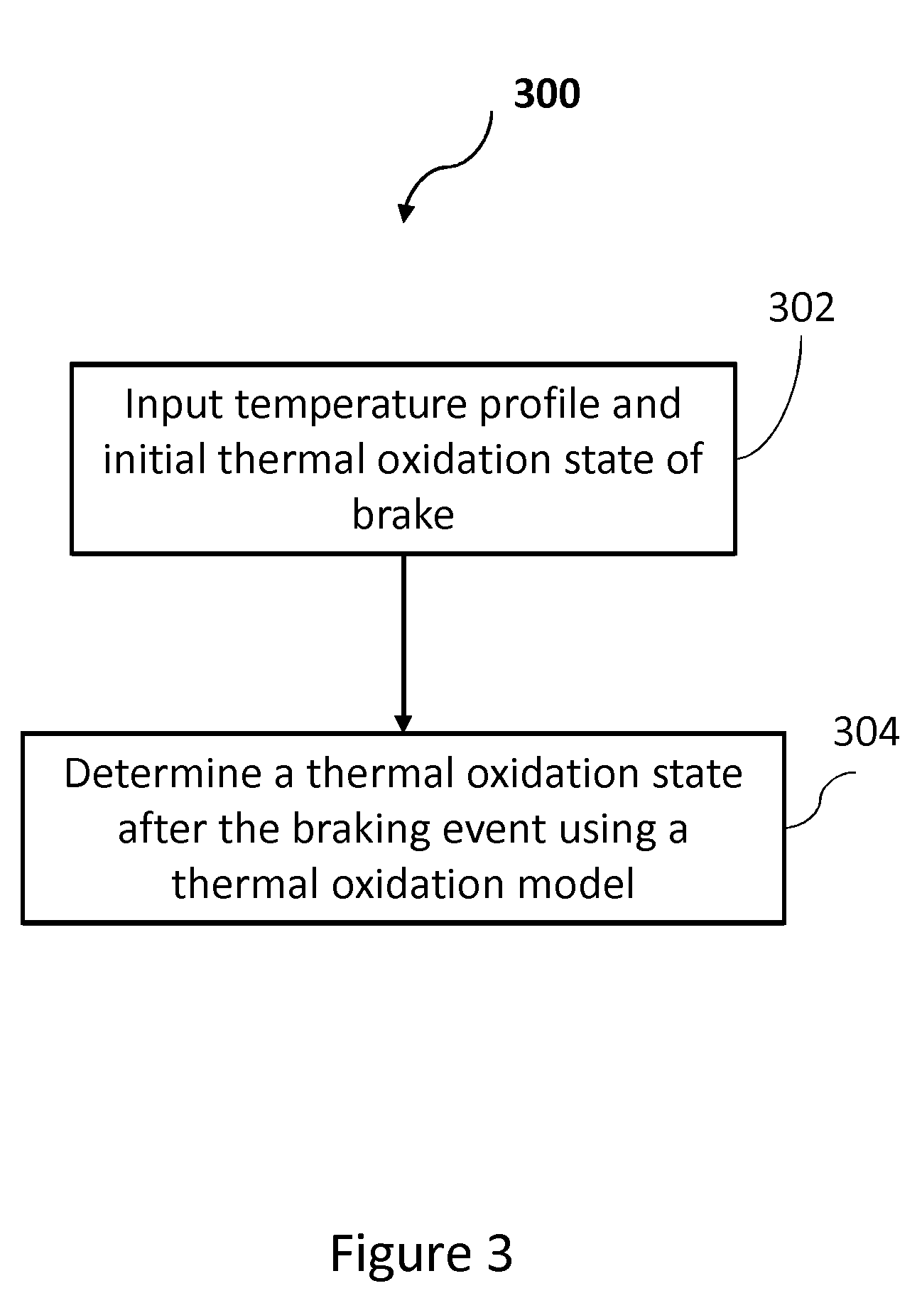
[0037] FIG. 3 summarizes a method 300, according to an embodiment of the present invention, of determining a thermal oxidation state of a brake, such as the brake assembly 200, of an aircraft landing gear assembly 102. The method 300 involves determining a thermal oxidation state of the brake assembly 200 after a braking event, using a thermal oxidation model based on an initial thermal oxidation state (which may also be referred to as the initial thermal oxidation level) before the braking event and a temperature profile of the brake with respect to time. The determined thermal oxidation state of the brake assembly 200 after the braking event may be referred to as an updated thermal oxidation state. This is because the thermal oxidation state of the brake assembly 200 after the braking event takes account of the change in the initial thermal oxidation state due to the braking event.
[0038] The braking event is an event relating to the application of the brake assembly 200. For example, a braking event may comprise one or more applications of the brake assembly 200 to slow or stop the aircraft 100. In some examples, the braking event may be a part of a time during which the brake assembly 200 is continuously being applied. Any time the brake assembly 200 is applied, the temperature of the brake assembly 200 may rise. This is because when brake assembly 200 is applied to reduce the speed of the aircraft 100, some of the kinetic energy of the aircraft 100 is absorbed into the brake assembly 200 as heat causing its temperature to rise. Therefore, whether or not the brake assembly 200 has been applied can be determined based on temperature variations of the brake assembly 200.
[0039] At block 302 of the method 300, the temperature profile and the initial thermal oxidation state of the brake assembly 200 are input. As explained above, the temperature profile indicates a variation of temperature with time. The input temperature profile may, for example, relate to a use cycle of the aircraft 100. For example, the temperature profile may be for an entire use cycle of the aircraft 100, e.g. the time from when the aircraft 100 is at a departure gate before a flight to when the aircraft 100 is at an arrival gate after a flight. Specifically, the temperature profile may indicate the variation of temperature over time for all braking events that take place during a cycle. In other examples, the temperature profile may not be for an entire use cycle of the aircraft 100. For example, the temperature profile may be over a single braking event, or a part of a cycle with many braking events. In some examples, a number of temperature profiles belonging to a particular use cycle may be used to determine the thermal oxidation state of the brake assembly 200 after that use cycle.
[0040] The temperature profile may, for example, relate to a use cycle that has occurred. In other words, the temperature profile may include actual data from the temperature sensor 212 of the aircraft 100 during a previous use cycle. In such examples, the temperature profile relates to real data. On the other hand, in some examples, the temperature profile may be a predicted temperature profile of a predicted future use cycle of the aircraft 100. In that context, a braking event may be a predicted future braking event.
[0041] The initial thermal oxidation state of brake assembly 200 is the thermal oxidation state of the brake assembly 200 before the braking event for which the updated thermal oxidation state is being determined. For example, for a new brake assembly 200 installed in aircraft 100, the initial oxidation state may indicate no oxidation. In some examples, the initial oxidation state for a newly installed brake assembly 200 may be set at installation by aircraft maintenance personnel and may either indicate no oxidation or some oxidation as assessed by the person(s) performing the installation. In examples where the brake assembly 200 is not new, the initial oxidation state may be the oxidation state calculated at a previous instance of method 300 being performed. In some examples, a brake or a brake component which is not new may be installed on aircraft 100. If the temperature profile information for all previous braking events involving that brake or brake component is available, the thermal oxidation state at installation may be determined using the available temperature profile information using method 300, or by other methods disclosed herein.
[0042] At block 304 of method 300, a thermal oxidation state after the braking event (updated thermal oxidation state) is determined using a thermal oxidation model. For example, a thermal oxidation model is applied based on the input temperature profile and the initial thermal oxidation state of the brake assembly 200. A thermal oxidation model, for example, indicates how the thermal oxidation state is expected to change with time for various temperatures starting from the initial thermal oxidation state. A thermal oxidation model is a model of the evolution of the thermal oxidation of the brake. Which thermal oxidation model is used may depend, for example, on the initial thermal oxidation state. The details and selection of appropriate thermal oxidation models is described further below. In some examples, the method 300 may be performed live during a use cycle of the aircraft 100. In the case of the method 300 being performed live (i.e. in real time or near real time), the temperature profile used may be from the temperature data acquired thus far by the temperature sensor 212, for example. At block 304, therefore, it is determined how the oxidation state, starting from the initial oxidation state, has changed as a result of the increased temperature associated with the braking event in question.
[0043] After the updated thermal oxidation state has been determined, the initial thermal oxidation state may be set to the updated thermal oxidation state. In this way, the initial thermal oxidation state is kept up to date with all previous braking events. In examples where the temperature profile relates to more than one braking event, the method 300 may be performed again in order to determine an updated thermal oxidation state after a subsequent braking event. Updating the initial thermal oxidation state in this manner may ensure that the initial thermal oxidation state being used for a subsequent braking event accounts for all the previous braking events.
[0044] In examples where the temperature profile for an entire use cycle of the aircraft 100, the method 300 may be performed to determine respective updated thermal oxidation states after each braking event within that use cycle. It will be understood that this process may be carried out sequentially in relation to the chronology of the braking events. This is so that the determination of the updated thermal oxidation state for each of the braking events is done from a starting point (an initial thermal oxidation state) which takes account of all previous braking events.
[0045] In the method 300, the updated thermal oxidation state after a braking event may, for example, be determined based on a high temperature interval, the initial thermal oxidation state and a thermal oxidation rate parameter, using an appropriate thermal oxidation model.
[0046] FIG. 4 is a flow diagram of a method 400 showing acts that may be performed as part of method 300. For example, the method 400 involves more specific examples of the block 304 of the method 300. Block 402 is identical to block 302 of the method 300, in that a temperature profile of the brake with respect to time and the initial thermal oxidation state of the brake assembly 200 are input. At block 404, the temperature profile is compared to a set of temperature criteria. The set of temperature criteria may include a set of temperature thresholds. For example, the set of temperature criteria may include a first temperature threshold of 400.degree. C. and a second temperature threshold of 750.degree. C. In other examples, different temperature thresholds may be used depending on the physical properties of the brake assembly 200. The comparison of the temperature profile may, for example, take place sequentially in time order of the temperature data contained in the temperature profile. For example, a temperature value may be compared to the set of temperature thresholds, and subsequently, the next temperature value in time may be compared to the set of temperature thresholds.
[0047] At block 406, it is determined if one or more of the temperature criteria are met. If, for example, none of the temperature thresholds are exceeded, the method 400 ends. It will be appreciated that thermal oxidation of the CC composite of the brake discs 202 is a process that is most significant at high temperatures. A comparison of the temperature profile with the set of temperature thresholds therefore identifies high temperature events corresponding to braking events that may result in thermal oxidation. As mentioned above, a braking event is, for example, an application of the brake assembly 200. However, a high temperature event is an event during which the temperature of the brake assembly exceeds at least one of the temperature thresholds as a result of a braking event. For example, if during a braking event (i.e. a braking application) the temperature of the brake assembly 200 remains below all temperature thresholds, then no high temperature events occurred during that braking event. On the other hand, if during a braking event the temperature of the brake assembly exceeds a temperature threshold, the part of the braking event for which that temperature threshold is exceeded may be referred to as a high temperature event. If more than one temperature threshold is exceeded, a high temperature event may be the part of the braking event for which the highest temperature threshold is exceeded.
[0048] The temperature thresholds may be set based on temperatures above which a significant amount of thermal oxidation is expected to occur. Therefore, the method 400 ends if none of the temperature thresholds are exceeded. This is because, in this example, no braking events causing a sufficiently high temperature for thermal oxidation have occurred. In such examples, the updated thermal oxidation state after the braking event may simply be set to the initial thermal oxidation state before the braking event in question.
[0049] On the other hand, if at least one of the temperature thresholds is exceeded, at block 408 of the method 400, a high temperature event corresponding to the braking event in question is identified. A high temperature event corresponds to the part of the temperature profile which is above the highest of the exceeded temperature thresholds. This is because the part of the temperature profile which is above the highest of the exceeded thresholds corresponds to the part of the braking event for which the highest temperature threshold is exceeded. The identification of a high temperature event is described with reference to FIG. 5. FIG. 5 is a graph illustrating a part of an example temperature profile. In the graph of FIG. 5, the vertical axis represents temperature of the brake assembly 200, and the horizontal axis represents time. In this example, profile part 502 indicates that the temperature of the brake assembly 200 exceeds a first temperature threshold 504 and a second temperature threshold 506. In this example, the high temperature event is identified as the part of the profile 502 above the second temperature threshold 506 as the second temperature threshold 506 is the highest temperature threshold which is exceeded.
[0050] The amount of thermal oxidation which occurs above the second temperature threshold 506 may be significantly greater for a given interval of time compared to the thermal oxidation above the first temperature threshold 504 but below the second temperature threshold 506. Therefore, in this example, the parts of the temperature profile below the second temperature threshold 506 are not taken into account. In other examples, for example when the method 400 is used for live oxidation state monitoring as described further below, the parts of the temperature profile between the two temperature thresholds may be taken into account. It should be appreciated that the graph of FIG. 5 is merely an illustration of an example for explanatory purposes.
[0051] At block 410, the interval of time taken by the high temperature event is determined to be the high temperature interval. As mentioned above, the updated thermal oxidation state may be determined based on (among other factors) the high temperature interval. In the example of FIG. 5, the high temperature interval is determined to be the time interval 508.
[0052] At block 412, a high temperature event value of the brake assembly 200 is determined for the high temperature interval. The high temperature event value is a value of temperature ascribed to the high temperature event. In some examples, the high temperature event value is the average temperature during the high temperature interval. Alternatives to the high temperature event value being the average temperature are described below in the context of live oxidation monitoring.
[0053] At block 414, an oxidation rate parameter is calculated based on the high temperature event value and physical characteristic information of the brake. For example, the oxidation rate parameter for the thermal oxidation reaction may be determined based on the Arrhenius equation shown as Equation 1 below:
k(T)=Ae-.sup.E.sup.A.sup./RT (1)
[0054] In Equation 1, k(T) is the thermal oxidation rate, A is a pre-exponential constant, E.sub.A is the activation energy of the carbon atoms of the CC composite components of brake assembly 200, R is the universal gas constant and T is the temperature. In this example, for a particular high temperature event, the temperature T in Equation 1 is set to the high temperature event value for the purpose of block 414. In this example, the thermal oxidation rate k(T) is the oxidation parameter determined at block 414. The values of activation energy E.sub.A, and the pre-exponential constant A may depend on the physical properties of the CC composite components of brake assembly 200 (in this example, the brake discs 202). For example, the values of these parameters may depend on the density, porosity, manufacturing process, contaminants present in the CC composite structures, the surface finish of the components and surface coatings of the brake assembly 200. The values of the activation energy E.sub.A, and the pre-exponential constant A may also vary depending on the high temperature event value and the initial thermal oxidation state. Therefore, in order to determine the oxidation parameter, appropriate values of activation energy E.sub.A, and the pre-exponential constant A may be selected based on the physical properties of the brake assembly 200, the high temperature event value and the initial thermal oxidation state before the braking event in question.
[0055] For example, the activation energy E.sub.A may be related inversely to temperature. The activation energy E.sub.A may become lower at a temperature at which oxygen molecules are able to penetrate past the surface of the brake discs 202 and oxidation of carbon deeper in the brake discs 202 can take place. The appropriate values of activation energy E.sub.A, and the pre-exponential constant A may, for example, be determined experimentally for different initial thermal oxidation amounts, temperatures and physical properties of the brake being considered before the method 400 is implemented.
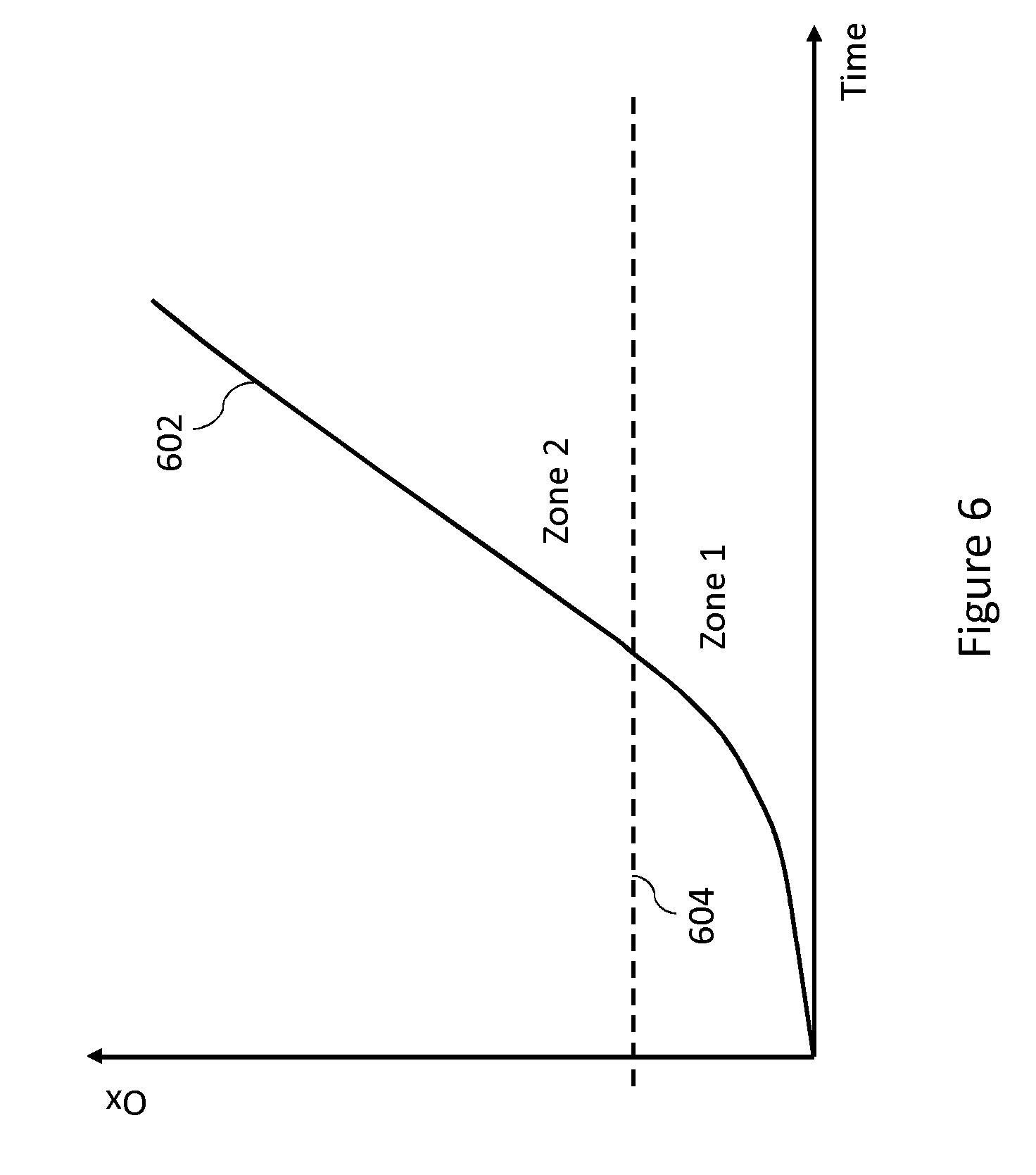
[0056] FIG. 6 is a graph of an example of the evolution with time of thermal oxidation of the brake discs of a brake assembly 200 for a specific temperature. The vertical axis of the graph in FIG. 6 represents a measure of the thermal oxidation indicated by the thermal oxidation state Ox. For example, the thermal oxidation state Ox may be the proportion of mass of the brake assembly 200 lost due to thermal oxidation of the brake discs 202. The evolution curve 602 shows how the proportion of mass lost due to thermal oxidation advances with time at the specific temperature. It should be noted that a different evolution curve would indicate the variation of the thermal oxidation state Ox over time for a different temperature value.
[0057] In this example, the thermal oxidation state Ox advances with time differently below a thermal oxidation state level 604, than it does above the thermal oxidation state level 604. The thermal oxidation state Ox (i.e. mass lost due to thermal oxidation) is shown to increase non-linearly with time below oxidation state level 604 and substantially linearly with time above oxidation state level 604, in this example. In this example, the thermal oxidation state increases at an accelerated rate with time until thermal oxidation state level 604 is reached. After thermal oxidation state level 604 is reached, the rate of change of thermal oxidation state Ox with time remains generally constant. The part of the graph of FIG. 6 below thermal oxidation state level 604 may be considered as a first thermal oxidation zone, namely Zone 1, and the part of the graph of FIG. 6 above thermal oxidation state level 604 may be considered as a second thermal oxidation zone, namely Zone 2, for example.
[0058] In some examples, different values of the activation energy E.sub.A, and the pre-exponential constant A may be used depending on which thermal oxidation zone the brake assembly 200 is in as indicated by the initial thermal oxidation state.
[0059] At block 416, a thermal oxidation model is selected based on the initial thermal oxidation state before the braking event. The thermal oxidation model describes the evolution of the thermal oxidation state Ox of the brake assembly 200 for different values of temperature. A thermal oxidation model which describes the evolution of the thermal oxidation state Ox in Zone 1 may be selected when the initial thermal oxidation state is in Zone 1. A thermal oxidation model which describes the evolution of the thermal oxidation state Ox in Zone 2 may be selected when the initial thermal oxidation state is in Zone 2. For example, a first thermal oxidation model, Model 1, may be selected for Zone 1, and a second thermal oxidation model, Model 2, may be selected for Zone 2. Model 1 for Zone 1, describing the non-linear change of thermal oxidation state Ox with time, may be represented by Equation 2. Model 2 for Zone 2, describing the linear change of thermal oxidation state Ox with time, may be represented by Equation 3 below.
Ox=1-[1-{k(T).times.t.sub.eq(1-n)}.sup.1/1-n] (2)
Ox=k(T).times.t.sub.eq (3)
[0060] In Equation 2 and Equation 3 above, k(T) is the thermal oxidation rate as defined by Equation 1. The parameter t.sub.eq is the equivalent time, which is the time it would take, at temperature T, to reach the thermal oxidation state Ox. The parameter n is referred to as the equation order and depends on the properties of the CC composite used in the brake assembly 200. The parameter n may, for example be experimentally determined for a brake using a particular CC composite.
[0061] In some examples, different thermal oxidation models to those described by Equations 2 and 3 may be used. In some examples, a single thermal oxidation model may be used which describes the evolution of the thermal oxidation state Ox for all thermal oxidation states Ox that are relevant to the brake assembly 200. In some examples, more than two thermal oxidation models may be used for respective ranges of thermal oxidation states Ox. The method 400 may be modified appropriately in order to use such alternative thermal oxidation models. For example, a different set of inputs may be applied to the thermal oxidation model, as appropriate, than are described in this specific example of the method 400.
[0062] It will be understood that block 416 may be performed at any stage of the method 400 once block 402 has been performed, because block 416 requires the initial thermal oxidation state.
[0063] At block 418, the updated thermal oxidation state for the high temperature event is determined using the selected thermal oxidation model based on the high temperature interval, the initial thermal oxidation state and the determined thermal oxidation rate parameter. For example, the time it would take to reach the initial thermal oxidation state from zero at the high temperature value is determined and the high temperature interval is added to this time in order to determine the value of t.sub.eq to be used in the selected thermal oxidation model. Inputting the thus determined value of t.sub.eq, as well as the thermal oxidation parameter into the equation selected from Equations 2 and 3 above results in, as an output, the updated thermal oxidation state of the brake assembly 200 after the high temperature event.
[0064] The updated thermal oxidation state may be set to the new initial thermal oxidation state for a subsequent use of the method 400 for a subsequent high temperature event in the temperature profile.
[0065] In some examples, the method 300 and/or 400 may be performed live during a use cycle when braking events are taking place. In such examples, part of the method 400, for example, may be modified to allow live brake oxidation monitoring, and the temperature profile may correspond to temperature values being measured live. For example, temperature information which the temperature sensor 212 provides may continuously be compared to the set of temperature criteria as per block 404 of method 400, and high temperature events may be identified substantially as they occur. It will be understood that even though this kind of oxidation state monitoring is described as live, the extent to which it occurs in real time will depend on various hardware and software (e.g. processing speed) limitations. For example, there may be a time delay between temperature values corresponding to a high temperature event being measured by the temperature sensor 212, and those values resulting ultimately in updated thermal oxidation states of the brake assembly 200.
[0066] For example, high temperature events may be identified as smaller parts of the temperature profile than in the example described above. Referring again to FIG. 5, the part of the profile part 502 occurring within the time interval indicated as 510 may be taken to be a high temperature event and the interval 510 as its high temperature interval. In this example, the high temperature event value may be taken to be the temperature measured at the beginning or the end of the high temperature interval 510, for example, or the average of the two temperature values. Unlike the above example, in the case of live monitoring, parts of the temperature profile between the first and second temperature thresholds may be taken into account even when the temperature exceeds the second temperature threshold 506. In the case of live monitoring, any part of the temperature profile above at least one temperature threshold, such as the part identified by interval 510, may be identified as a high temperature event. It will be understood that such modifications may allow the thermal oxidation state of the brake assembly 200 to be updated as high temperature events corresponding to braking events are taking place. In some examples, high temperature events may be identified based on the time between subsequent temperature measurements taken by the temperature sensor 212. For example, the interval 510 may be the interval of time between subsequent temperature measurements taken by the temperature sensor 212.
[0067] The methods 300 and 400 may be used in order to determine the thermal oxidation state of the brake assembly 200 after an actual use cycle of the aircraft 100 or in a live manner during an actual use cycle. In such examples, this may be done based on one or more temperature profiles encompassing braking events within that use cycle. As mentioned above, in some examples, the thermal oxidation state of the brake assembly 200 is determined in respect of a use cycle which has actually occurred using temperature profile information collected by the temperature sensor 214.
[0068] On the other hand, in some examples, the method 300 or 400 may be used to predict a future thermal oxidation state of the brake assembly 200 after a first plurality of predicted future use cycles of the aircraft 100. The first plurality of future use cycles may be a number of cycles after which a thermal oxidation threshold is reached. Each predicted future use cycle may include a respective plurality of braking events. For each predicted future use cycle, the predictions may be based on a respective predicted temperature profile of the brake assembly 200 and a current thermal oxidation state. The current thermal oxidation state is, for example, the oxidation state taking into account all the previous braking events experienced by the brake assembly 200.
[0069] For example, the predicted temperature profiles may be input into the method 300 or 400, for example in time order, to determine the future thermal oxidation state of brake assembly 200. The predicted temperature profile of a predicted future use cycle may be predicted based on previous temperature profiles for previous actual use cycles of the aircraft 100. For example, using the parts of previous temperature profiles relating to the landing phase, landing phase parts of the temperature profile for a future use cycle may be predicted. For the purpose of predicting a future thermal oxidation state, high temperature intervals, high temperature event values, etc. may be stored in a computer readable storage medium when the method 300 or 400 is being carried out for actual use cycles of aircraft 100.
[0070] In some examples, data from previous cycles may not be available, for example, because brake the assembly 200 may be new. In some examples, enough data may not be available to reliably predict temperature profiles for predicted future use cycles. In such examples, predetermined temperature profiles may be used. The predetermined temperature profiles may be profiles typically expected for the future use cycle of aircraft 100.
[0071] The predicted temperature profiles may, for example, take into account the future flight schedule of the aircraft 100. For example, the aircraft 100 may be expected to land at an airport with a short runway requiring high energy (i.e. high temperature) braking upon landing for some of its predicted future use cycles. For those predicted future use cycles, the predicted temperature profiles may indicate high energy braking upon landing. It will be appreciated that various other factors may be taken into account when predicting temperature profiles such as taxiing time at various phases of a predicted future use cycle, waiting time between a taxiing phase and the preceding landing phase, and the like.
[0072] As mentioned above, the first plurality of predicted future use cycles may be a number of predicted future cycles after which the predicted future thermal oxidation state reaches a thermal oxidation threshold. For example, the prediction of the future thermal oxidation state may stop after a cycle in which the thermal oxidation threshold is reached. In some examples, the prediction of the future thermal oxidation state may stop as soon as the thermal oxidation threshold is reached. The thermal oxidation threshold may be an oxidation state at which servicing or replacement of the brake assembly 200 or a component of the brake assembly 200 is required. For example, the brake assembly 200 may require a service if its mass is reduced by between 4% and 6.5%, for instance 5.7%, where the selected percentage threshold may vary depending, for instance, on the original, manufactured disc density. In this example, the first plurality of predicted future use cycles is the number of cycles it takes for the proportion of mass lost due to thermal oxidation to reach or exceed, for instance, 5.7% (i.e. being within the range 4% to 6.5%).
[0073] On the other hand, in some examples, the prediction of the future thermal oxidation state may stop at the end of a predicted future use cycle during which the future thermal oxidation state approaches close to the thermal oxidation threshold such that the future thermal oxidation state can be expected to reach the thermal oxidation threshold during the next predicted future use cycle. In such examples, the thermal oxidation threshold may be considered reached within the first plurality of predicted future use cycles. This is because, in reality, an aircraft 100 with a brake assembly 200 expected to reach the thermal oxidation threshold in a strict sense in the very next cycle would not be permitted to fly and a service or replacement relating to the brake assembly 200 may take place at that point.
[0074] Using the first plurality of predicted future use cycles, an indication may be given as to how many use cycles can take place before the brake assembly 200 or a component of the brake assembly 200 requires servicing or replacement due to thermal oxidation. In the examples where the thermal oxidation threshold is strictly reached or exceeded during the last of the first plurality of future cycles, the number of cycles before a service or replacement is required due to thermal oxidation may be predicted as one fewer than the number of cycles in the first plurality. In examples where the prediction of the future thermal oxidation state stops when the thermal oxidation threshold is expected to be reached in the next cycle after the first plurality, the first plurality is taken as the number of cycles before a service or replacement due to thermal oxidation is required.
[0075] FIG. 7 is a flow diagram of a method 700 of determining an amount of brake wear caused by a braking event, using a brake wear model based on an amount of energy absorbed by the brake assembly 200 due to the braking event and a density parameter of the brake assembly 200. The amount of brake wear may be determined for all braking events where energy is input into the brake assembly 200 in a process involving friction that would cause a surface of the brake discs to wear. For example, wear of the brake discs due to friction may cause the length of the brake discs 202 (length L as shown in FIG. 2) to decrease as brake disk material is lost by the action of friction.
[0076] For example, the amount of brake wear may be determined for those braking events which do not involve any high temperature events. For the method 700, a braking event may, for example, be identified based on the temperature profile as an event where the temperature of the brake assembly 200 increases. In some examples, a braking event may simply be identified based on an indication that brake assembly 200 has been applied. For example, the computing system 104 of the aircraft 100 may detect when brake assembly 200 is applied and released.
[0077] At block 702 of the method 700, the energy input into the brake assembly 200 during the braking event is determined. The energy input into the brake assembly 200 may, for example, be determined based on the characteristics of the aircraft 100 during the braking event, such as a mass of the aircraft 100, the velocity of the aircraft 100 during the braking event, etc. The energy absorbed by the brake assembly 200 can be calculated based on such characteristics of the aircraft 100 by determining the kinetic energy of the aircraft 100. For example, a given proportion of the kinetic energy of the aircraft 100 may be absorbed by the brake assembly 200 to reduce the kinetic energy of the aircraft 100. In some examples, the energy input into the brake assembly 200 may be determined based on measurements acquired by the instruments 106 of the aircraft 100. For example, the instruments 106 may include a tachometer associated with the wheel 214 to which the brake assembly 200 is associated. In such examples, the tachometer measures the rotational speed of the wheel 214, and the energy absorbed by the brake assembly 200 can be determined using the change of the rotational speed with respect to time.
[0078] In other examples, if the mass of the brake assembly 200 is known, the energy absorbed may be determined based on the increase in temperature of the brake assembly 200 taking into account the specific heat of the brake assembly 200. In some examples, the mass of the brake assembly 200 may be determined based on the thermal oxidation state of the brake assembly 200 determined according to the above described methods, because, as described above, the thermal oxidation state may be expressed as an amount of mass lost from brake assembly 200 due to thermal oxidation.
[0079] At block 704 of the method 700, a density parameter of the brake assembly 200 is determined. The density parameter, for example, is a parameter indicating the decrease in density of the brake assembly 200 compared with the original density, taking into account lost mass. The density of the brake assembly 200 may decrease, for example, due to thermal oxidation. It will be understood that thermal oxidation causes a reduction in mass because carbon atoms react with oxygen to form carbon dioxide or carbon monoxide and are thus removed from brake discs 202. However, thermal oxidation may not necessarily change the volume of the brake discs 202. This is because thermal oxidation may not act uniformly on a particular surface of a brake disc and may take place up to a certain depth inside the brake disc.
[0080] The density parameter may be expressed as (1-Ox) where the thermal oxidation state Ox is expressed as a number between zero and one. For example, the density of the brake assembly 200 is reduced by a factor (1-Ox) compared to the initial density before any thermal oxidation took place (i.e. when the brake assembly 200 was new). Therefore, the density parameter may be determined based on the initial oxidation state before the braking event.
[0081] In some examples, the reduced density of the brake assembly 200 may be determined based on measurements by instruments included in the instruments 106. For example, the mass of the brake assembly 200 may be calculated based on an amount of energy absorbed by the brake assembly 200 (based on measurements from a tachometer, for example) and the consequent increase in its temperature (based on measurements from temperature sensor 212, for example). The reduced density of the brake assembly 200 may be determined based on the calculated mass of the brake assembly 200. The aircraft 100 may include a wear pin associated with brake assembly 200. Typically, a wear pin provides an indication of the reduction in length L of a brake and therefore an indication of the brake wear. The wear pin may be checked between cycles by ground crew, for example, and an updated volume value of the brake assembly 200 acquired. In some examples, there may be other ways to measure the change in length L of the brake assembly 200. For example, a length sensor may be provided for the brake assembly 200, and/or electrically actuated brakes may be used. An updated volume value may be determined, based on reduced length L, and used to determine the reduced density from the mass. During a single cycle, the change in volume of brake assembly 200 may be insignificant for the purpose of calculating the density parameter, and an updated volume may be acquired after a number of cycles. From the reduced density, the density parameter may be determined.
[0082] At block 706 of the method 700, an amount of brake wear caused by the braking event is determined, using a brake wear model based on the energy absorbed by the brake assembly 200 and the density parameter from block 704. For example, the mass of the brake assembly 200 lost due to wear during the wear event is determined using the brake wear model of Equation 4 below.
m wear = W + X .times. E brake + Y .times. E brake 2 + Z .times. E brake 3 ( 1 - 0 x ) ( 4 ) ##EQU00001##
[0083] In Equation 4 above, m.sub.wear is the mass lost due to wear during the braking event, E.sub.brake is the energy absorbed by the brake assembly 200, and W, X, Y and Z are constants. The constants W, X, Y and Z may, for example, be determined by experiment beforehand, and may vary depending on the properties of the brake assembly 200. The brake wear amount for a braking event may be determined as a reduction in length L of the brake assembly 200 based on the reduction of mass due to brake wear during that braking event.
[0084] As mentioned above, the initial thermal oxidation rate is used to determine the density parameter in some examples. In these examples, when a braking event takes place during which a high temperature event also occurs, the initial thermal oxidation state may be used for the determination of block 706. This is because brake wear occurs on a much shorter timescale than thermal oxidation.
[0085] The amount of brake wear determined for a braking event may be added to the amount of brake wear from all previous braking events of the brake assembly 200 in order to determine the total brake wear amount.
[0086] The method 700 may, for example, be performed live during a time when braking events are taking place, or for a use cycle which has already occurred using the relevant data from that use cycle. The method 700 may also be used in order to predict a future brake wear amount for the brake assembly 200 after a second plurality of predicted future use cycles of the aircraft 100. The second plurality of predicted future use cycles may be a number of cycles after which a brake wear threshold is reached. Each predicted future use cycle may include a respective plurality of braking events. For example, the method 700 may be performed for each braking event in the second plurality of predicted future use cycles. The wear amount from each of those braking events may be added up to predict the future brake wear amount for the second plurality of predicted future use cycles. For each predicted future use cycle, the predictions may be based on predicted amounts of energy absorbed by the brake during respective braking events, and respective predicted density parameters of the brake for respective braking events. For example, braking events may be identified and energy absorbed by brake assembly 200 for those braking events determined based on the predicted temperature profiles. In other examples, predicted amounts of absorbed energy may be based on data from previous cycles. If the brake assembly 200 is new, or enough previous data is not available, the predicted amounts of energy may be predetermined.
[0087] For the purpose of predicting the future brake wear amount, the method 700 may be used in combination with the method 300 or 400. In these examples, the up to date initial thermal oxidation state just before each predicted braking event (e.g. a predicted future braking event) is known. In this way, the mass of the brake assembly 200, and therefore the density parameter, may be determined using the initial thermal oxidation before the future braking event in question.
[0088] As mentioned above, the second plurality of predicted future use cycles may be a number of predicted future cycles after which the predicted future brake wear amount reaches a brake wear threshold. For example, the prediction of the future brake wear amount may stop after a cycle in which the brake wear threshold is reached. In some examples, the prediction of the future brake wear amount may stop as soon as the total brake wear amount reaches the brake wear threshold. The brake wear threshold may be a total amount of brake wear at which servicing or replacement of the brake assembly 200 or a component of the brake assembly 200 is required. For example, a brake assembly such as the brake assembly 200 of FIG. 2 may require a service if its length L has been reduced by, say, 22% to 24%, depending, for example, on the kind of discs and original, manufactured density thereof. For an exemplary disk having an original length L of around 221 mm, a reduction in length of around 50 mm may trigger servicing or replacement. In this example, the second plurality of predicted future use cycles is the number of cycles it takes for the total brake wear amount to reach or exceed, for instance 50 mm (again, for an original disc having a length L of around 221 mm).
[0089] On the other hand, in some examples, the prediction of the future brake wear amount may stop at the end of a predicted future use cycle during which the total brake wear amount approaches close to the brake wear threshold such that the total brake wear amount can be expected to reach the brake wear threshold during the next predicted future use cycle. In such examples, the brake wear threshold may be considered reached within the second plurality of predicted future use cycles. This is because, in reality, an aircraft 100 with the brake assembly 200 expected to reach the brake wear threshold in a strict sense in the very next cycle would not be permitted to fly and a service or replacement relating to the brake assembly 200 may take place at that point.
[0090] Using the second plurality of predicted future use cycles, an indication may be given as to how many use cycles can take place before the brake assembly 200 or a component of the brake assembly 200 requires servicing or replacement due to brake wear. In the examples where the brake wear threshold is strictly reached or exceeded during the last of the second plurality of future cycles, the number of cycles before a service or replacement is required due to brake wear may be predicted as one less than the number of cycles in the second plurality. In examples where the prediction of the future brake wear amount stops when the brake wear threshold is expected to be reached in the next cycle after the second plurality, the second plurality is taken as the number of cycles before a service or replacement due to brake wear is required.
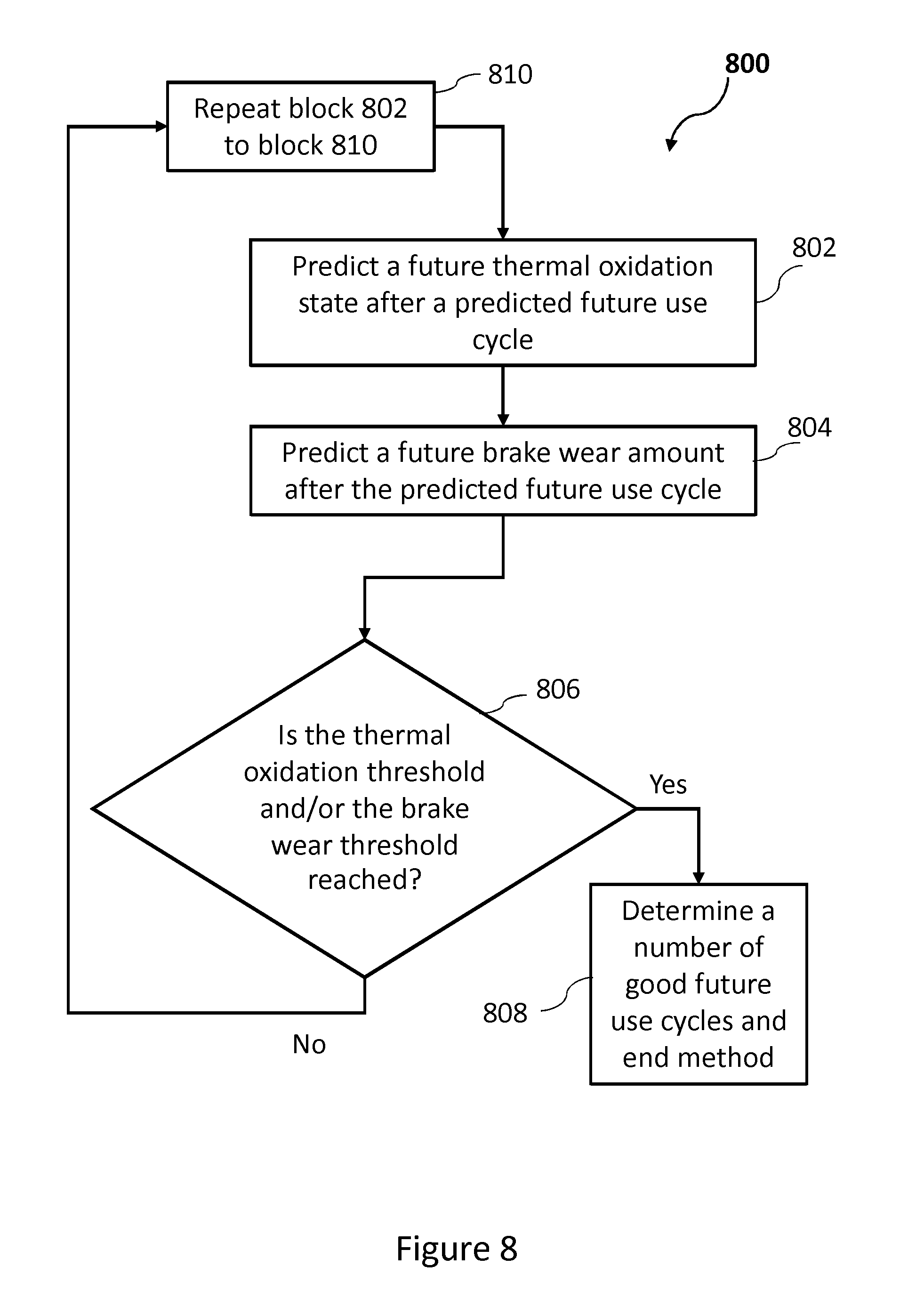
[0091] FIG. 8 is a flow diagram of a method 800 for determining a number of good future use cycles until one of the thermal oxidation threshold and the brake wear threshold is reached. The number of good future use cycles is the remaining number of future use cycles before one of the thermal oxidation threshold or the brake wear threshold is reached. The method 800 may be performed for a number of predicted future use cycles until the first of the thresholds is reached. The method 800 involves predicting a future thermal oxidation state and a future brake wear amount after a predicted future use cycle and, if one of the thermal oxidation threshold and the brake wear threshold is reached, determining a number of good future use cycles before either of the thresholds is reached. If one of the thresholds is not reached, the predictions are performed for the next predicted future use cycle. As in the above examples, each predicted future use cycle includes a plurality of braking event. For each predicted future use cycle the predictions are based on a respective predicted temperature profile of the brake, a current thermal oxidation state, predicted amounts of energy absorbed by the brake during respective braking events, and respective predicted density parameters of the brake for respective braking events.
[0092] The number of good future use cycles is a number of cycles after which servicing or replacement of the brake assembly 200 or a component of the brake assembly 200 is required. It will be appreciated that service or replacement in relation to the brake assembly 200 may be carried out when one of the thermal oxidation threshold or the brake wear threshold is first reached. Which threshold is reached first may, for example, depend on the way the aircraft 100 is handled during use and its flight schedule. For example, if the aircraft 100's schedule involves flying to mostly airports with long runways, short taxiing routes, etc., the brake wear threshold may be reached first. This is because, in such examples, the temperature of the brake assembly 200 may not often exceed any of the temperature thresholds relating to thermal oxidation. On the other hand, the aircraft 100 may often experience high energy braking (e.g. due to short runways) causing temperatures above the thresholds related to thermal oxidation. In such examples the thermal oxidation threshold may be reached first.
[0093] At block 802 of the method 800, a future thermal oxidation state after a predicted future use cycle is predicted. The prediction of the future thermal oxidation state is performed as described above, for example, using an appropriate thermal oxidation model based on a predicted temperature profile of the predicted future use cycle in question. At block 804 of the method 800, a future brake wear amount after the same predicted future use cycle is predicted. The prediction is performed as described above in the context of method 700.
[0094] At block 806 of the method 800, it is determined whether the thermal oxidation threshold and/or the brake wear threshold is reached. For example, if the thermal oxidation threshold is reached, the method 800 proceeds to block 808 at which a number of good future use cycles, before either of the thermal oxidation threshold or the brake wear threshold is reached, is determined, and the method 800 ends. For example, if the thermal oxidation threshold is strictly reached or exceeded after a given number of predicted future use cycles, the number of good future use cycles is one less than that given number. For example, if the thermal oxidation threshold is expected to be reached in the very next predicted future use cycle, the number of good future use cycles is determined as the number of predicted future use cycles for which the method 800 has been performed thus far.
[0095] On the other hand, if it is determined that the brake wear threshold is reached, the method proceeds to block 808 where a number of good future use cycles is determined, and the method 800 ends. For example, if the brake wear threshold is strictly reached or exceeded after a given number of predicted future use cycles, the number of good future use cycles is one less than that given number. For example, if the brake wear threshold is expected to be reached in the very next predicted future use cycle, the number of good future use cycles is determined as the number of predicted future use cycles for which method 800 has been performed thus far.
[0096] If, for example, both the thresholds are reached, the method 800 proceeds to block 808 where a number of remaining good future use cycles, before either the thermal oxidation threshold or the brake wear threshold is reached, is determined and the method 800 ends. In this example, if at least one of the thresholds is strictly reached or exceeded after a given number of predicted future use cycles, the number of good future use cycles is one less than that given number. Otherwise, the number of good future use cycles is determined as the number of predicted future use cycles for which the method 800 has been performed thus far.
[0097] If the brake wear threshold is not reached, the method 800 proceeds to block 810 and blocks 802 to 810 are repeated for the next predicted future use cycle.
[0098] In this way, a number of good future use cycles may be predicted based on which of the thermal oxidation threshold and the brake wear threshold is reached first. This is because, the brake assembly 200 may require a service or replacement, or a component of the brake assembly 200 may require a service or replacement once the first of these thresholds is reached. It will be appreciated, for example, that brake assembly 200 will not continue to be used if the thermal oxidation threshold is reached but the brake wear threshold is not. It should also be appreciated that blocks of the method 800 may be performed in any suitable order. For example block 804 may be performed before block 802 and/or block 810 may be performed before block 806.
[0099] One or more of the above described methods, namely the methods 300, 400, 700 and 800, or any of their variations (e.g. live determination of oxidation or brake wear, or prediction of future thermal oxidation state or future brake wear, etc.) may be performed by a processor of the computing system 104 of the aircraft 100, for example, based on instructions stored in a computer readable storage medium of the computing system 104. For example, monitoring of the thermal oxidation state (subsequent to use cycles or live) may be performed by a processor of computing system 104. Alternatively, or in addition, monitoring of the brake wear (subsequent to use cycles or live) may be performed by a processor of the computing system. Alternatively, or in addition to any of these examples, predictions relating to the future thermal oxidation state and/or the future brake wear state may be performed by a processor of the computing system 104. The methods may be performed, for example, using data from the instruments 106. For example, temperature data as measured by the temperature sensor 212 may be used. In the case of prediction, the future temperature profiles and/or other predicted data may be predicted by a processor of the computing system 104. Alternatively, the data for prediction may be determined on a computing system not on board the aircraft 100, and may be stored in a computer readable storage medium of the computing system 104.
[0100] An indicating device 108 of the aircraft 100 may be used to provide the pilots and/or ground crew indications relating to the thermal oxidation state, brake wear amount, a number of cycles before the thermal oxidation threshold is reached, a number of cycles before the brake wear threshold is reached and/or a number of good future use cycles. For example, such indications may allow the ground crew to assess aspects of the brake assembly 200 more quickly than visual or other physical inspection alone. Such indications may also allow appropriate scheduling of services and replacements in relation to the brake assembly 200. This may prevent delays due to grounding of the aircraft 100 at a time when a service or replacement is not scheduled because ground crew determine an issue with the brake assembly 200 which could not have been known without predictions relating to thermal oxidation and/or brake wear.
[0101] Indications regarding thermal oxidation and/or brake wear to the pilot(s) may assist, for example, in the pilots indicating to ground crew when a service or replacement in relation to the brake assembly 200 may be required. Indications of the state of the brake assembly 200 for a previous cycle may also assist the pilot(s) of the aircraft 100 in assessing their brake application behaviour. For example, the indications may show that a particular change in braking behaviour may lead to less thermal oxidation per cycle and a greater number of good future use cycles. For example, this may occur in the case where the thermal oxidation threshold is predicted to be reached first. When one or more of the above described methods are being performed live by a processor of computing system 104, indications in relation to the thermal oxidation and/or brake wear of the brake assembly 200 may allow the pilot(s) to adjust brake application behaviour substantially in real time in order to preserve the brake assembly 200. For example, the pilot(s) may not start taxiing the aircraft 100 immediately after a landing with high energy braking, if permitted to do so, such that the temperature of the brake assembly 200 does not remain above a temperature threshold relating to thermal oxidation.
[0102] One or more of the above described methods, namely the methods 300, 400, 700 and 800, or any of their variations (e.g. live determination of oxidation or brake wear, or prediction of future thermal oxidation state or future brake wear, etc.) may be performed by a computing apparatus such as computing apparatus 900 shown in FIG. 9, for example. The computing apparatus 900 may be external to the aircraft 100. Computing apparatus 900 may comprise a processor 902 and a computer readable storage medium 904. The processor 902 may be configured to execute instructions stored on the storage medium 904. The storage medium 904 may store instructions for performing all or part of any of the above described methods. Data, such as temperature profile information, may be provided to the computing apparatus 900 for performing the methods disclosed herein. In the case of live monitoring, data from the aircraft may be transmitted to the computing apparatus 900. For example, any of the above methods may be performed by computing apparatus 900 and the resulting indications reported to personnel responsible for the care and/or use of the aircraft 100.
[0103] All or part of the instructions for performing the above described methods may be generated and/or the methods may be performed using any suitable software or combination of software. In one example, "MATLAB" may be used to generate all or part of the instructions for a processor such as processor 902 or a processor of computing system 104 to carry out any of the above methods. In other examples, other software packages may be used. For example, any suitable programming language, development environment, software package, or the like may be used. Other examples of programming languages include PYTHON, C++, C, JAVASCRIPT, FORTRAN etc.
[0104] It will be appreciated that the methods disclosed herein allow monitoring (live or subsequent to a use cycle) of the thermal oxidation state and/or brake wear state. The methods also allow predictions in relation to future thermal oxidation states and brake wear states of the brake assembly 200.
[0105] It is to noted that the term "or" as used herein is to be interpreted to mean "and/or", unless expressly stated otherwise. Although the invention has been described above with reference to one or more preferred embodiments, it will be appreciated that various changes or modifications may be made without departing from the scope of the invention as defined in the appended claims.
* * * * *
D00000
D00001
D00002
D00003
D00004
D00005
D00006
D00007
D00008
D00009
XML
uspto.report is an independent third-party trademark research tool that is not affiliated, endorsed, or sponsored by the United States Patent and Trademark Office (USPTO) or any other governmental organization. The information provided by uspto.report is based on publicly available data at the time of writing and is intended for informational purposes only.
While we strive to provide accurate and up-to-date information, we do not guarantee the accuracy, completeness, reliability, or suitability of the information displayed on this site. The use of this site is at your own risk. Any reliance you place on such information is therefore strictly at your own risk.
All official trademark data, including owner information, should be verified by visiting the official USPTO website at www.uspto.gov. This site is not intended to replace professional legal advice and should not be used as a substitute for consulting with a legal professional who is knowledgeable about trademark law.