Form Changing Toy
Ikoma; Akiko ; et al.
U.S. patent application number 16/196735 was filed with the patent office on 2019-08-29 for form changing toy. This patent application is currently assigned to TOMY Company, Ltd.. The applicant listed for this patent is TOMY Company, Ltd.. Invention is credited to Akiko Ikoma, Shigeru Kanauchi, Shu Katayama, Takashi Nakase, Mitsutoshi Tokuyama, Hiroyuki Watanabe.
| Application Number | 20190262736 16/196735 |
| Document ID | / |
| Family ID | 67331317 |
| Filed Date | 2019-08-29 |


View All Diagrams
| United States Patent Application | 20190262736 |
| Kind Code | A1 |
| Ikoma; Akiko ; et al. | August 29, 2019 |
FORM CHANGING TOY
Abstract
A form changing toy is provided with a power source being configured to provide power, a first power transmission mechanism, a second power transmission mechanism, a third power transmission mechanism, a connection switching mechanism, and a form switching mechanism. The connection switching mechanism is configured to alternatively switch between a first connection and a second connection. The first connection is between the first power transmission mechanism and the second power transmission mechanism. The second connection is between the first power transmission mechanism and the third power transmission mechanism. The form switching mechanism is configured to switch between a first form and a second form of the form changing toy. The second power transmission mechanism is configured to perform a first operation when the form switching mechanism switches. The third power transmission mechanism is configured to perform a second operation when the form switching mechanism switches.
| Inventors: | Ikoma; Akiko; (Tokyo, JP) ; Nakase; Takashi; (Tokyo, JP) ; Katayama; Shu; (Tokyo, JP) ; Watanabe; Hiroyuki; (Tokyo, JP) ; Tokuyama; Mitsutoshi; (Tokyo, JP) ; Kanauchi; Shigeru; (Tokyo, JP) | ||||||||||
| Applicant: |
|
||||||||||
|---|---|---|---|---|---|---|---|---|---|---|---|
| Assignee: | TOMY Company, Ltd. Tokyo JP |
||||||||||
| Family ID: | 67331317 | ||||||||||
| Appl. No.: | 16/196735 | ||||||||||
| Filed: | November 20, 2018 |
| Current U.S. Class: | 1/1 |
| Current CPC Class: | A63H 31/08 20130101; A63H 29/00 20130101; A63H 33/003 20130101; A63H 30/04 20130101 |
| International Class: | A63H 33/00 20060101 A63H033/00; A63H 31/08 20060101 A63H031/08; A63H 30/04 20060101 A63H030/04 |
Foreign Application Data
| Date | Code | Application Number |
|---|---|---|
| Feb 26, 2018 | JP | 2018-032408 |
Claims
1. A form changing toy comprising: a power source being configured to provide power; a first power transmission mechanism; a second power transmission mechanism being connected to the first power transmission mechanism to perform a first operation by the power, the first power transmission mechanism being configured to transmit the power from the power source to the second power transmission mechanism; a third power transmission mechanism being connected to the second power transmission mechanism to perform a second operation which is different from the first operation by the power, the second power transmission mechanism being configured to transmit the power from the first transmission mechanism to the third transmission mechanism; a connection switching mechanism being configured to alternatively switch between a first connection and a second connection, the first connection being between the first power transmission mechanism and the second power transmission mechanism, the second connection being between the first power transmission mechanism and the third power transmission mechanism; and a form switching mechanism being configured to switch between a first form and a second form of the form changing toy, the second power transmission mechanism being configured to perform the first operation when the form switching mechanism switches between the first form and the second form, the third power transmission mechanism being configured to perform the second operation when the form switching mechanism switches between the first form and the second form.
2. The form changing toy according to claim 1, further comprising a cam, wherein the first transmission mechanism includes a first gear, the connection switching mechanism includes second and third gears being concentric with an axis, where a number of teeth of the second gear and a number of teeth of the third gear is different, the second gear and the third gear adjacently provided to the second gear are engaged with the first gear, the cam is connected to and configured between the second and third gears to urge the third gear towards the second gear in a direction in which the axis extends, and the first power transmission mechanism is connected to the second power transmission mechanism when a distance between the third gear to the second gear is the shortest, and the first power transmission mechanism is connected to the third power transmission mechanism when a distance between the third gear to the second gear is the longest.
3. The form changing toy according to claim 2, wherein the connection switching includes a locking mechanism which is operated by the third power transmission mechanism the locking mechanism is configured to lock the third gear in a position separated from the second gear, and configured to release the third gear when the third power transmission mechanism reaches a predetermined operation amount.
4. The form changing toy according to claim 1, wherein the first operation is walking.
Description
CROSS-REFERENCE TO THE RELATED APPLICATION
[0001] The present application claims priority under 35 U.S.C. 119 to Japanese Patent Application No. 2018-032408 filed on Feb. 26, 2018. The contents of this application are incorporated herein by reference in their entirety.
BACKGROUND OF THE INVENTION
Filed of the Invention
[0002] The present invention relates to a form changing toy.
Description of Related Art
[0003] It is a robot toy capable of mutually changing from the first form as a doll form to the second form, which is different from the first form, automatically or by a remote control. Further, it is well-known to provide a deforming means which changes from the first form to the second form, a deforming means which changes from the second form to the first form, and a moving means which is movable in any of the first form and the second form (please see Japanese Patent Application Publication No. 2014-144211).
[0004] However, in the aforementioned form changing toy, from the view point of movements, the toy only runs before and after changing the form, so that there was a problem of lacking interest factors.
[0005] The description herein of advantages and disadvantages of various features, embodiments, methods, and apparatus disclosed in other publications is in no way intended to limit the present invention. For example, certain features of the preferred described embodiments of the invention may be capable of overcoming certain disadvantages and/or providing certain advantages, such as, e.g., disadvantages and/or advantages discussed herein, while retaining some or all of the features, embodiments, methods, and apparatus disclosed therein.
SUMMARY OF THE INVENTION
[0006] The disclosed embodiments of the present invention have been developed in view of the above- mentioned and/or other problems in the related art. The disclosed embodiments of the present invention can significantly improve upon existing methods and/or apparatuses.
[0007] An object of the present invention is to provide a form changing toy with interest factors by performing other operations after changing a form.
[0008] In a first aspect of the invention, a form changing toy is provided with a power source being configured to provide power, a first power transmission mechanism, a second power transmission mechanism, a third power transmission mechanism, a connection switching mechanism, and a form switching mechanism. The second power transmission mechanism is connected to the first power transmission mechanism to perform a first operation by the power. The first power transmission mechanism is configured to transmit the power from the power source to the second power transmission mechanism. The third power transmission mechanism is connected to the second power transmission mechanism to perform a second operation which is different from the first operation by the power. The second power transmission mechanism is configured to transmit the power from the first transmission mechanism to the third transmission mechanism. The connection switching mechanism is configured to alternatively switch between a first connection and a second connection. The first connection is between the first power transmission mechanism and the second power transmission mechanism. The second connection is between the first power transmission mechanism and the third power transmission mechanism. The form switching mechanism is configured to switch between a first form and a second form of the form changing toy. The second power transmission mechanism is configured to perform the first operation when the form switching mechanism switches between the first form and the second form. The third power transmission mechanism is configured to perform the second operation when the form switching mechanism switches between the first form and the second form.
[0009] In a second aspect of the invention according to the first aspect, the form changing toy is further provided with a cam. The first transmission mechanism includes a first gear. The connection switching mechanism includes second and third gears being concentric with an axis, where a number of teeth of the second gear and a number of teeth of the third gear is different. The second gear and the third gear adjacently provided to the second gear are engaged with the first gear. The cam is connected to and configured between the second and third gears to urge the third gear towards the second gear in a direction in which the axis extends. The first power transmission mechanism is connected to the second power transmission mechanism when a distance between the third gear to the second gear is the shortest. The first power transmission mechanism is connected to the third power transmission mechanism when a distance between the third gear to the second gear is the longest.
[0010] In a third aspect of the invention according to the third aspect, the form changing toy according to claim 2, wherein the connection switching includes a locking mechanism which is operated by the third power transmission mechanism. The locking mechanism is configured to lock the third gear in a position separated from the second gear, and configured to release the third gear when the third power transmission mechanism reaches a predetermined operation amount.
[0011] A fourth aspect of the invention according to the first aspect, the first operation is walking.
BRIEF DESCRIPTION OF THE DRAWINGS
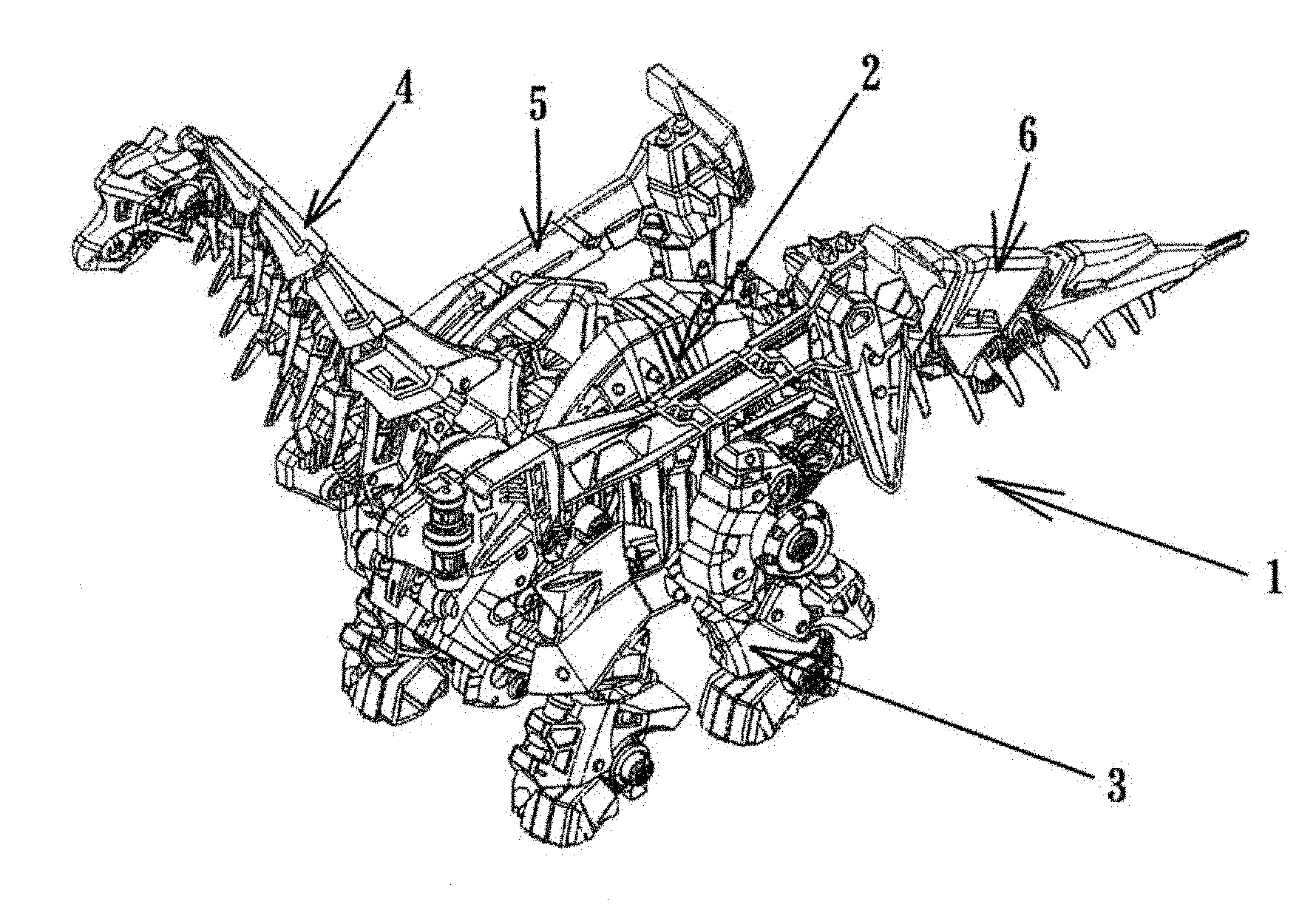
[0012] FIG. 1 is a perspective view showing a form changing toy of the first embodiment;
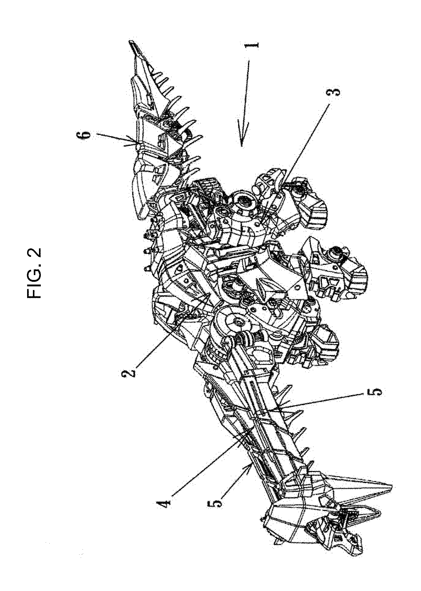
[0013] FIG. 2 is a perspective view showing the form changing toy in a state after changing the form;
[0014] FIG. 3 is a partial cutout perspective view of the form changing toy;
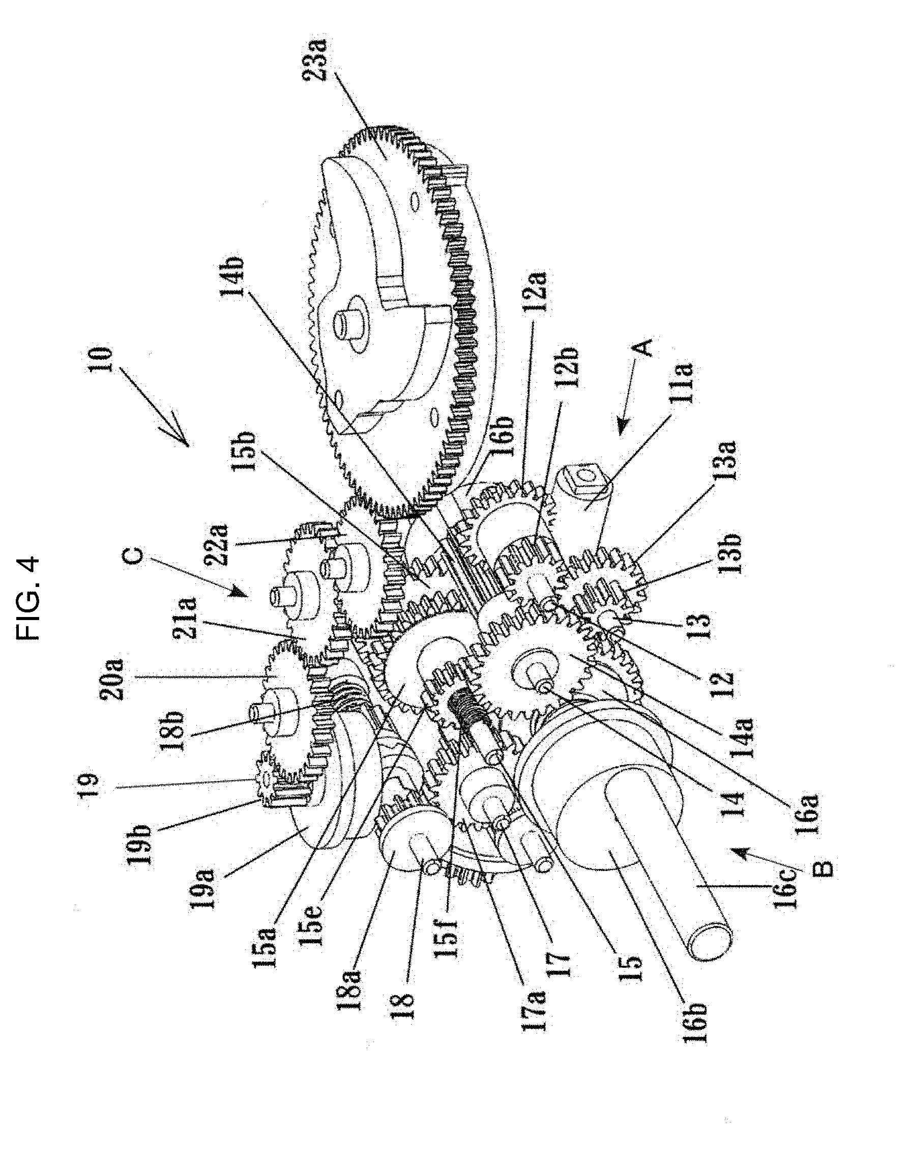
[0015] FIG. 4 is a perspective view of a power transmission mechanism;
[0016] FIG. 5 is a perspective view showing a power switching mechanism and a connection switching mechanism;
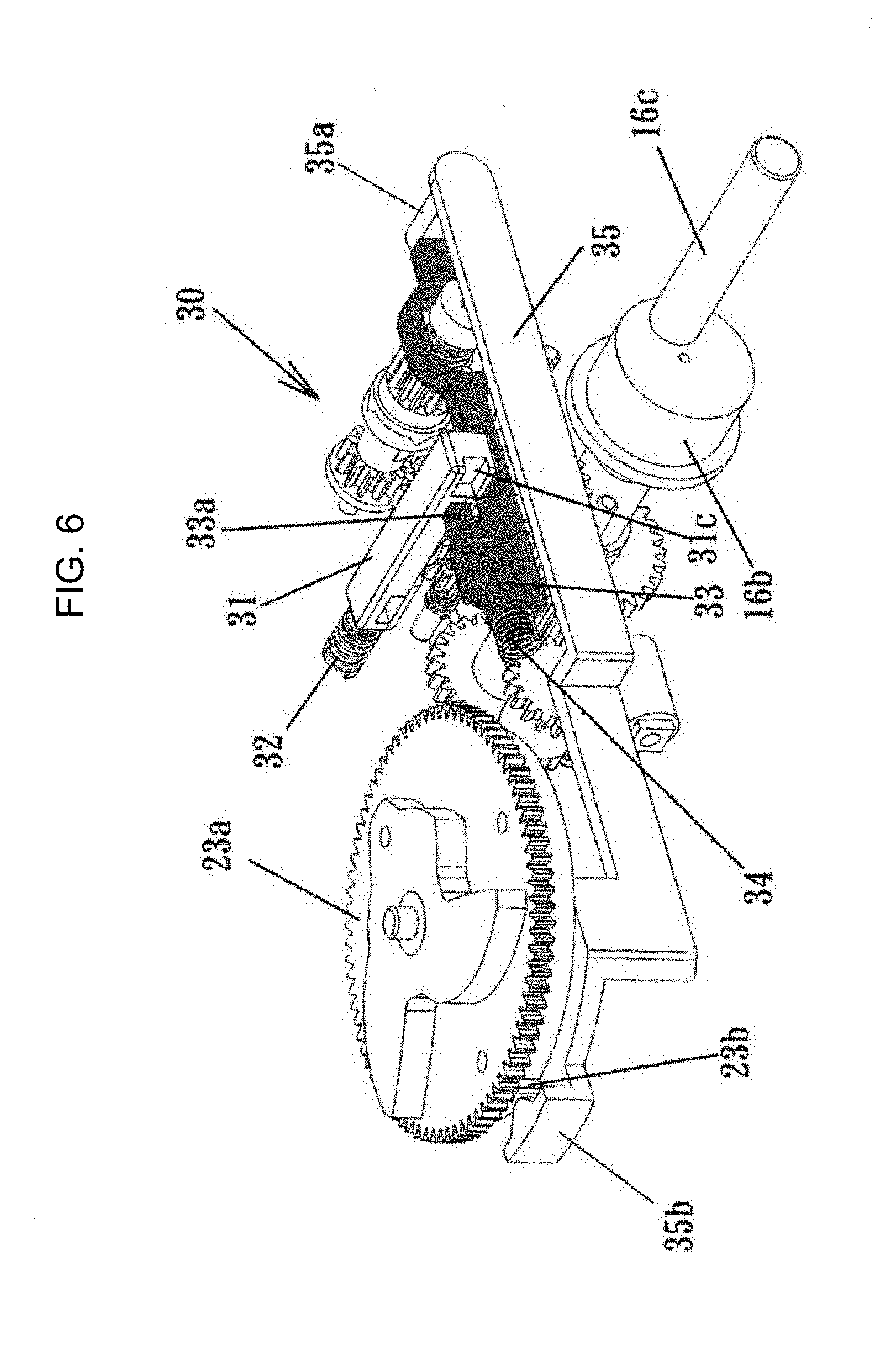
[0017] FIG. 6 is a perspective view showing a locking mechanism;
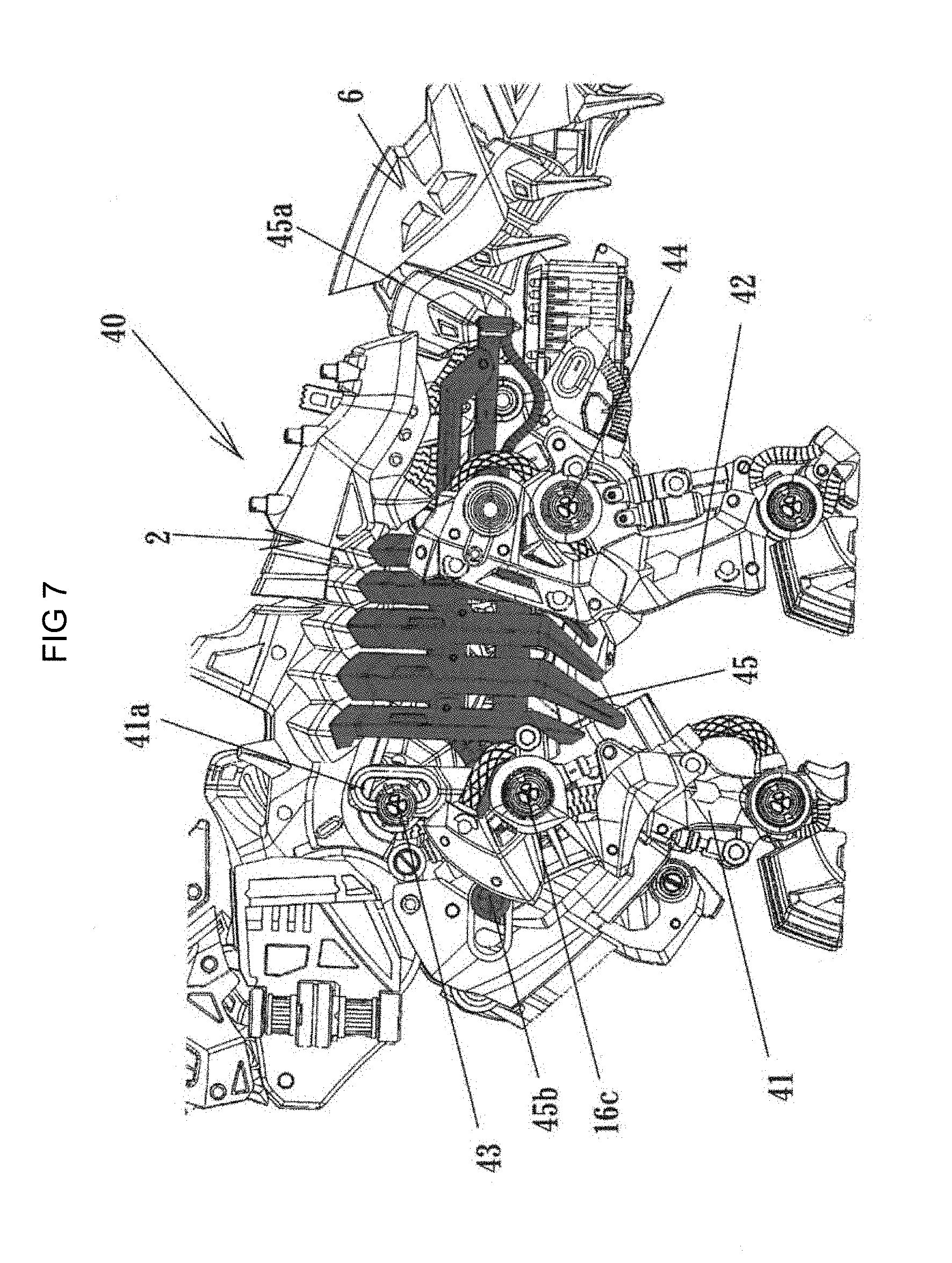
[0018] FIG. 7 is a perspective view showing an operation mechanism of leg parts;
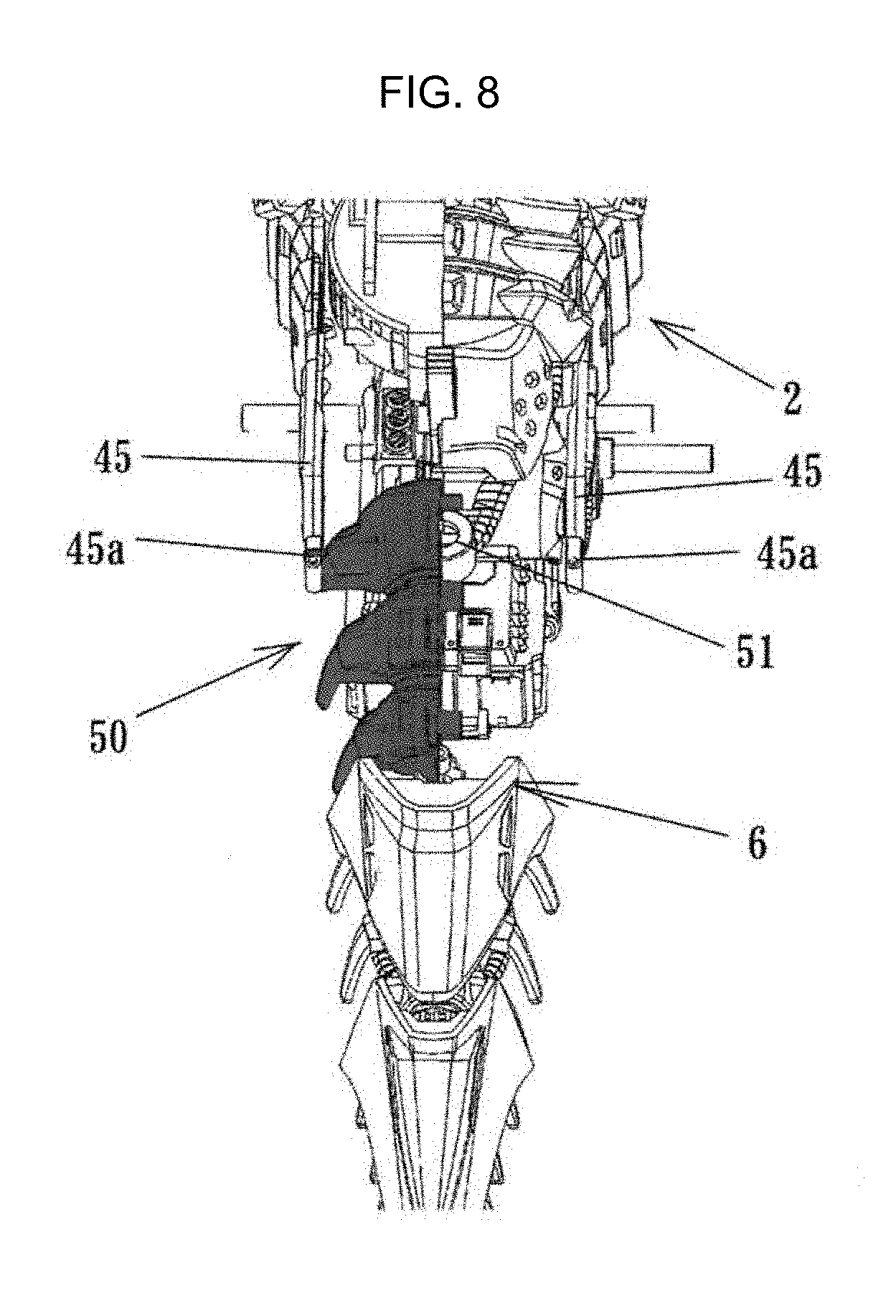
[0019] FIG. 8 is a perspective view showing a tail part swinging mechanism;
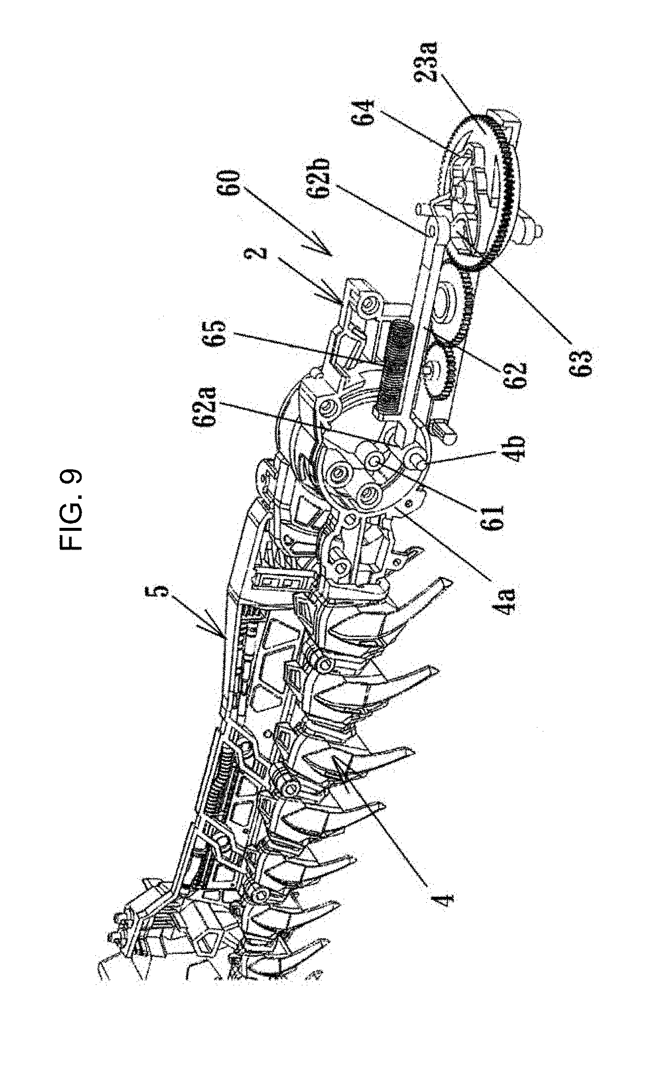
[0020] FIG. 9 is a schematic view showing a first neck part swinging mechanism;
[0021] FIG. 10 is a schematic view showing a second neck part swinging mechanism;
[0022] FIG. 11 is a perspective view showing a wing part swinging mechanism;
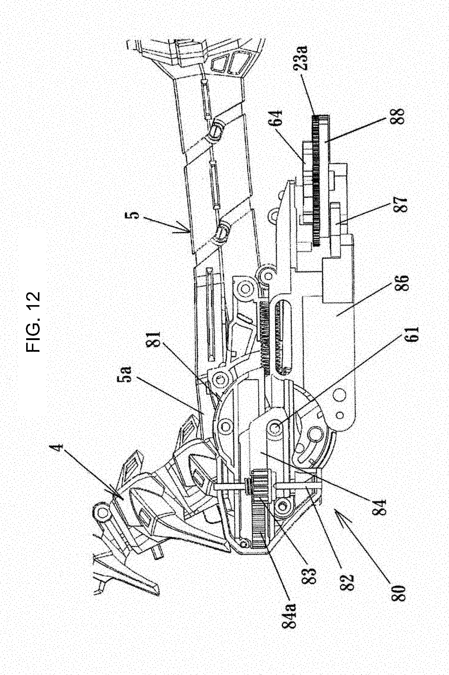
[0023] FIG. 12 is cross-sectional surface view showing a state in which a wing part is along a body part in the wing part swinging mechanism; and
[0024] FIG. 13 is cross-sectional surface view showing a state in which a wing part is along a neck part in the wing part swinging mechanism.
DETAILED DESCRIPTION OF PREFERRED EMBODIMENTS
[0025] In the following paragraphs, some embodiments of the invention will be described by way of example and not limitation. It should be understood based on this disclosure that various other modifications can be made by those in the art based on these illustrated embodiments.
[0026] Hereinafter, embodiments of a form changing toy according to the present invention will be described based on embodiments shown in the drawings.
[0027] A form changing toy 1 shown in FIGS. 1 and 2 is shaped as Brachiosaurus of a dinosaur, and includes components of a body part 2, leg parts 3, a neck part 4 including a head part, a wing part 5, a tail part 6, etc. The form changing toy 1 is provided with a power source such as a motor, a gear, etc. in the body part 2. In a state shown in FIG. 1, the form changing toy 1 moves forward while operating the leg parts 3, the neck part 4, and the tail part 6 by the power source, and after only working a predetermined number of steps, it is stopped at that place. Next, as shown in FIG. 2, the neck part 4 is inclined to a lower side, and then, the wing part 5 is rotated in a manner moving along the neck part 4. Next, the neck part 4 moves up and down in accordance with the wing part 5. The up and down movement of the neck part 4 is repeated for a predetermined number times so as to complete one cycle. After that, it is repeated.
[0028] As shown in FIG. 3, a power transmission system 10 is installed in the body part 2. In the power transmission system 10, as shown in FIG. 4, an output gear (worm gear) 11a of the motor 11 as a power source meshes with a large gear 12a of a shaft 12 which extends perpendicularly with respect to an output shaft, and a small gear 12b which is integral with the large gear 12a meshes with a large gear 13a of a shaft 13 which is parallel to the shaft 12. Further, the small gear 13b which is integral with the large gear 13a meshes with a large gear 14a of a shaft 14 which is parallel to the shaft 13. In the large gear 14a, a small gear 14b which is provided on the same shaft and has wide width is formed. The small gear 14b meshes with a gear 15a of a shaft 15 which is parallel to the shaft 14. The gear (sliding gear) 15a is slidably arranged in a shaft direction with respect to the shaft 15. On the other hand, to 15, the gear 15b is fixed. These gear 15a and gear 15b have different number of teeth each other. In each surface of the gear 15a and the gear 15b which face each other, cams 15c, 15d are formed. Further, a small gear 15e (selected gear) which is integral with the gear 15a is formed, and these gears 15a, 15e are urged in the gear 15b direction by a spring 15f.
[0029] Further, in the power transmission system 10, the power of the motor is transmitted to the gears 15a, 15b, 15e through the gears 11a, 12a, 12b, 13a, 13b, 14a, 14b. By the way, the first power transmission mechanism A includes the gears 11a, 12a, 12b, 13a, 13b, 14a, 14b.
[0030] In this state, the gear 15e (selected gear) meshes with a gear 16a of a crank shaft 16. The gear 16a is provided as a part of the second power transmission mechanism B which operates the leg parts 3. At the both ends of the shaft 16, a disk 16b is formed, and an eccentric shaft 16c projects in the outer surface of each of the disks 16b. The second power transmission mechanism includes the gear 16a, the disks 16b, and the eccentric shafts 16c.
[0031] By the gear 14b of the first power transmission mechanism A, the gear 15a and the gear 15b are rotated, but they have different number of teeth so as to gradually occur the relative deviation. Therefore, the gear 15e is gradually moved against the urging force of the spring 15f by the cams 15c, 15d, and at the end, it is separated from the gear 16a and meshes with a gear 17a. The gear 17a is provided in a part of the third power transmission mechanism C. The gears 15a, 15e, the cams 15c, 15d, and the spring 15f constitute the connection switching mechanism.
[0032] In the third power transmission mechanism C, the gear 17a meshes with a gear 18a of a shaft 18 which is parallel to the shaft 17, and a gear 18b which is integrated to share the same shaft meshes with a crown gear 19a. In the crown gear 19a, a gear 19b is provided to the shaft 19, and the gear 19b is connected to a final gear 23a through intermediate gears 20a, 21a, 22a. The third power transmission mechanism includes the gear 17a to the final gear 23a.
[0033] In the aforementioned power transmission system 10, the power is transmitted to the second power transmission mechanism B through the first power transmission mechanism A, and therefore, the leg parts 3 are operated. At the timing which will describe later, the power transmission to the leg parts 3 is disconnected, and the final gear 23a is operated by the third power transmission mechanism C. Other components, for example, a neck part 4, a wing part 5, are operated through the final gear 23a. In this case, a timing is determined by the final gear 23a.
[0034] FIGS. 5 and 6 show a locking mechanism 30 which disconnects the second power transmission mechanism B from the first power transmission mechanism A, and connects the first power transmission mechanism A to the third power transmission mechanism C, and maintains the state in a predetermined period of time. By the way, the locking mechanism 30 constitutes a part of a connection switching mechanism. As shown in FIG. 5, the locking mechanism 30 is provided with a slide body 31 which moves in a direction parallel to the shaft 15 of the gear 15a. The slide body 31 is provided with pieces 31a, 31b, and the gear (sliding gear) 15a is inserted between these pieces 31a, 31b. The slide body 31 is always urged in a direction of a gear 15b by a spring 32.
[0035] When the gear 15a moves against the urging force of the spring 15f by the cams 15c, 15d, the slide body 31 is also moved in the right direction of FIG. 5 against the urging force of the spring 32.
[0036] When the cams 15c, 15d of the gears 15a, 15b reach the valley, the slide body 31 returns to the original position. It is provided with a lock piece 33 which moves in a direction perpendicular to the moving direction of the slide body 31 in order to stay at the moved position for a predetermined period of time (time until the final gear 23a is rotated by a single revolution)(see FIG. 6). The lock piece 33 has a nail 33a, and the nail 33a is urged to move to the slide body by the spring 34. On the other hand, on the end surface of the slide body 31, a notch 31c is formed, and the nail 33a of the lock piece 33 is inserted to the notch 31c so as to stop the slide body 31 at the position moved against the urging force of the spring 32.
[0037] Further, the locking mechanism 30 is provided with a lock releasing piece 35 which releases the locking of the lock piece 33. Of the lock releasing piece 35, one end 35a is engaged with the top end of the lock piece 33, and the other end 35b contacts to the projection 23b which is formed at the circumference of the final gear 23a of the third power transmission mechanism C.
[0038] By the locking mechanism 30, when the slide body 31 is moved against the urging force of the spring 32, the nail 33a of the lock piece 33 is inserted into the notch 31 so as to prevent the slide body 31 from returning. As a result, the gear 15e maintains a state of meshing with the gear 17a. That is, the first power transmission mechanism A maintains a state of connecting with the third power transmission mechanism C.
[0039] When the projection 23b at the circumference of the final gear 23a of the third power transmission mechanism C is operated, the top end 35a of the lock releasing piece 35 retrieves the lock piece 33 against the urging force of the spring 34. Therefore, since the locking of the slide body 31 is released, the slide body 31 is returned by the urging force of the spring 32. That is, the gear 15a is returned to the original state, so that the gear 15e is separated from the gear 17a and is meshed with the gear 16a.
[0040] That is, in this power transmission system 10, the power is transmitted from the first power transmission mechanism A to the second power transmission mechanism B, and with this, the eccentric shafts 16c are rotated, and the leg parts 3, which will be described later, move so as to walk. During that period, the connection of the first power transmission mechanism A with the second power transmission mechanism B is disconnected by moving the gear 15a by the cams 15c, 15d, and it is switched to the third power transmission mechanism C. This state is maintained by the lock piece 33. By the rotation of the final gear 23a in the third power transmission mechanism C, the lock releasing piece 35 is operated by the projection 23b. Then, the locking of the lock piece 33 is released, so that the gear 15a is returned. With this, the first power transmission mechanism A is connected to the second power transmission mechanism B again.
[0041] FIG. 7 shows a leg part operation mechanism 40. The leg parts 3 are provided with right and left front legs 41 and right and left back legs 42. In the right and left front legs 41, the middle parts are rotatably supported by the eccentric shafts 16c which project from the body part 2. The upper end parts are rotatably supported by the shafts 43 fixed to the body part 2 through elongated holes 41a. On the other hand, in the right and left back legs 42, the middle parts are rotatably supported to the body part 3 by shafts 44. The middle parts of the right and left front legs 41 and the upper parts of the right and left back legs are connected to each other by the connecting body 45.
[0042] In the leg part operation mechanism 40, the front legs 41 swing by the eccentric shafts 16c which are rotated by the power. Such operation of the front legs 41 is transmitted to the upper parts of the back legs 42 through the connecting body 45, and the back legs 42 swing around the shafts 44. Therefore, when the front legs 41 swing in the front direction, the back legs 42 swing in the back direction.
[0043] By the way, in the leg part operation mechanism 40, the eccentric positions of the eccentric shafts 16c of the right and left front legs 41 are positioned with 180 degrees phase difference each other. That is, when the left front leg 41 swings forward, the right front leg 41 swing rearward. By repeating this movement, the form changing toy 1 moves forward.
[0044] In the form changing toy 1, a tail part swinging mechanism 50 which swings the tail part 6 right and left is provided. The front end of the tail part 6 is rotatably supported in the right and left direction by a shaft 51 as shown in FIG. 8. On both the right and left side surfaces of the front end of the tail part 6, the rear end 45a of the connecting body 45 is connected.
[0045] According to the tail part swinging mechanism 50, the right and left connecting bodies 45 alternatively move in the front and back direction, so that the tail part swings right and left by the rear end 45a of each of the connecting bodies 45.
[0046] Further, in the form changing toy 1, as shown in FIG. 9, the first neck part swinging mechanism 60 which swings the neck part 4 up and down is provided. The neck part 4 includes a disk 4a at the base end. The center of the disk 4a is rotatably supported to the body part 2 by a shaft 61. In the peripheral edge of the disk 4a, a shaft 4b is formed in a projecting manner. On the shaft 4b, one end 62a of the connecting rod 62 is rotatably supported. At the other part of the connecting rod 62, a pin 63 is provided. The connecting rod 62 extends to the final gear 23a of the third power transmission mechanism C which is positioned in the rear side. On the upper surface of the final gear 23a, a cam 64 is formed. By urging the connecting rod 62 in the direction of the final gear 23a by a spring 65, the pin 63 is contacted to the cam 64.
[0047] According to the first neck part swinging mechanism 60, the connecting rod 62 extends and retreats in the direction of the neck part 4 in accordance with a shape of the cam 64. When the connecting rod 62 projects to the direction of the neck part 4 (left side in FIG. 9), the disk 4a is rotated in the clockwise direction in FIG. 9 around the shaft 61, so that the neck part 4 is moved upwardly. On the other hand, when the connecting rod 62 moves in the direction of the gear 23a (right side in FIG. 9), the disk 4a is rotated in the counterclockwise direction in FIG. 9 around the shaft 61, so that the neck part 4 is moved downwardly.
[0048] Further, as shown in FIG. 10, the form changing toy 1 is provided with the second neck part swinging mechanism 70 which is separated from the aforementioned first neck part swinging mechanism 60. In the neck part swinging mechanism 70, a lever 72 is rotatably supported to the body part 2 by a shaft 71. In one end part of the lever 72, an elongated hole 72a is formed. The pin 45a arranged in the front end of the connecting body 45 is inserted into the elongated hole 72a. On the other hand, on the disk 4a of the base end of the neck part 4, a pin 4c is provided. To this pin 4c, the other end 72b of the lever 72 is contacted.
[0049] According to the second neck part swinging mechanism 70, the lever 72 is rotated in the clockwise direction in FIG. 10 in response to the displacement of the connecting body 45b. Then, the restriction of the pin 4c is released, so that the neck part 4 is rotated downwardly by its own weight.
[0050] Further, when the connecting body 45b moves in the opposite direction, the lever 72 is rotated in the counterclockwise direction in FIG. 10. Accordingly, the disk 4a is rotated in the counterclockwise direction through the pin 4c, so that the neck part 4 is rotated upwardly.
[0051] Further, as shown in FIGS. 11 and 12, the form changing toy 1 is provided with a wing part swinging mechanism 80 which swings the wing part 5 right and left.
[0052] In the wing part swinging mechanism 80, a disk 81 is rotatably held to the shaft 61. To the disk 81, a shaft 82 is rotatably provided, and on the shaft 82, a gear 83 and the base part 5a of the wing part 5 are fixedly provided. The shaft 82 is rotatably supported to a bracket 81a of the disk 81.
[0053] Further, in the wing part swinging mechanism 80, as shown in FIGS. 12 and 13, a slide body 84 is provided to the disk 81. A rack 84a is formed in the slide body 84, and the rack 84a meshes with the gear 83. The slide body 84 is always urged to the rear side by a spring 85 shown in FIG. 11, and is stored inside the disk 81 by a stopper which is not shown in the figure.
[0054] Further, in the body part 2, a slide body 86 is provided. The top end of the slide body 86 is arranged to face the rear the end surface of the slide body 84.
[0055] On the other hand, one end of a lever 87 is supported in the vicinity of the final gear 23a, and the lever 87 is moved in a direction parallel to the lower surface of the final gear 23a. In the middle part lower surface of the lever 87, a pin (not shown) projects, and the pin is inserted into a groove cam 88 which is formed in the lower surface of the final gear 23a. The top end of the lever 87 is connected to the slide body 86.
[0056] In the wing part swinging mechanism 80, when the wing part 5 is positioned along the body part 2, the lever 87 is operated forward by the groove cam 88 of the final gear 23a, and as shown in Fig. 12, it becomes a state in which the top end of the slide body 86 is pushed forward. With this structure, the slide body 84 is pushed forward, and the rack 83a is moved forward.
[0057] In this state, when the lever 87 is retrieved (moved right side in FIG. 12) by the groove cam 88 of the final gear 23a, the slide body 86 is moved to the rear side accordingly. Therefore, the slide body 84 is moved rearwardly by the urging force of the spring 85, and in response to that, the rack 84a moves the rear side and the gear 83 is rotated. Then, the wing part 5 is rotated outwardly, and is rotated by the position along the neck part 4 (see FIG. 11).
[0058] In the form changing toy 1 of the present embodiment, first, the power transmission mechanism B is operated by the power transmission mechanism A which is operated by the power (see FIG. 4). With this structure, the leg parts 3 are operated for walking, and at the point, the connecting body 45 is operated so as to move the neck part 4 up and down (see FIGS. 7 and 10) and swing the tail part 6 in the right and left direction (see FIG. 8). In this way, when the leg parts 3 are operated to walk only a predetermined number of steps, the power transmission mechanism A is separated from the power transmission mechanism B and is connected to the power transmission mechanism C. Therefore, it stops walking, and the up-and-down movement of the neck part 4 (see FIG. 9) which relies on the final gear 23a of the power transmission mechanism B, and the development of the wing part 5 toward the front side (see FIGS. 11 to 13) are performed. The development of the wing part 5 toward the front side is operated when the neck part 4 reaches the lowest point, and after that, the wing part 5 is moved up and down a couple of times (2 to 3 times) in the state of being along the neck part 4. In this way, one cycle ends, and after that, the aforementioned operation is repeated.
[0059] In the aforementioned form changing toy 1, the operation of the leg parts 3 is linked so as to operate the neck part 4 and the tail part 6. In this case, the up-and-down movement width of the neck part 4 depends on the movement of the connecting body 45 and the length of the lever 72, the shape of the elongated hole 72a, etc.
[0060] Further, in the up-and-down movement width of the neck part 4 which is operated by the cams 64, 88 of the final gear 23a, the open-and-close timing, etc. of the wing part 5 is determined by the shape of the cams 64, 88.
[0061] Further, the power switching mechanism in the form changing toy 1 of the embodiment includes two gears 15a, 15b which have different number of teeth meshing with the gear 14b of the input side. One of these gears (sliding gear) 15a is slidably provided in the shaft direction with respect to the shaft 15. The cams 15c, 15d are formed in the surface to which the gear 15a, 15b face each other. The output gear (selected gear) 15e and the gear 15a are integrated, and two gears (gear to be selected) 16a, 17a are arranged with an appropriate interval on the shafts 16, 17 which are arranged parallel to the shaft 15. By the cam function which causes the rotational difference of the gears 15a, 15b rotated by the input side gear 14b, the sliding gears 15a, 15e move in the shaft direction, and the selected gear 15e is separated from the gear 16a which is currently meshed, and meshes with the gear to be selected 17a.
[0062] By appropriately setting an interval of the gears to be selected 16a, 17a, the gear to be selected 15e is alternatively meshed with the gears to be selected 16a, 17a, and both gears 16a, 17a can be temporally meshed at the same time.
[0063] In the aforementioned embodiment, it shows an example, but it is needless to say that the operation amount of each component part, timing etc. can be arbitrarily set.
Effect of the Invention
[0064] The form changing is automatically performed, and before and after the form changing, the operation changes, so that a form changing toy having unexpected interesting factors can be realized.
[0065] The positive cam is operated by two gears which have different number of teeth and mesh with the same gear, and one of the two gears contacts to and separates from the other one of the gears, so that a connection switching mechanism with a simple structure can be realized.
[0066] By the operation amount of the third power transmission mechanism which is different from the positive cam, the length of the second operation can be easily adjusted.
[0067] In the form changing, the operation of walking and other than the walking can be alternatively performed.
* * * * *
D00000
D00001
D00002
D00003
D00004
D00005
D00006
D00007
D00008
D00009
D00010
D00011
D00012
D00013

XML
uspto.report is an independent third-party trademark research tool that is not affiliated, endorsed, or sponsored by the United States Patent and Trademark Office (USPTO) or any other governmental organization. The information provided by uspto.report is based on publicly available data at the time of writing and is intended for informational purposes only.
While we strive to provide accurate and up-to-date information, we do not guarantee the accuracy, completeness, reliability, or suitability of the information displayed on this site. The use of this site is at your own risk. Any reliance you place on such information is therefore strictly at your own risk.
All official trademark data, including owner information, should be verified by visiting the official USPTO website at www.uspto.gov. This site is not intended to replace professional legal advice and should not be used as a substitute for consulting with a legal professional who is knowledgeable about trademark law.