Form Changing Toy
KATAYAMA; Shu ; et al.
U.S. patent application number 16/195388 was filed with the patent office on 2019-08-29 for form changing toy. This patent application is currently assigned to TOMY Company, Ltd.. The applicant listed for this patent is TOMY Company, Ltd.. Invention is credited to Akiko IKOMA, Shigeru KANAUCHI, Shu KATAYAMA, Takashi NAKASE, Mitsutoshi TOKUYAMA, Haruhisa UJITA, Hiroyuki WATANABE.
| Application Number | 20190262735 16/195388 |
| Document ID | / |
| Family ID | 66934419 |
| Filed Date | 2019-08-29 |


View All Diagrams
| United States Patent Application | 20190262735 |
| Kind Code | A1 |
| KATAYAMA; Shu ; et al. | August 29, 2019 |
FORM CHANGING TOY
Abstract
A form changing toy includes a power source, an operation part, a movable part, a switch, and an operation mechanism. The operation part is connected to the power source to perform a predetermined movement by power from the power source. The switch is configured to be reversibly moved between a first position and a second position manually. The operation mechanism is configured to move, by the power, the movable part by making the movable part abut the power source or by making the movable part abut the operation part when the switch is at the second position, and is configured to separate the movable part from the power source or the movable part from the operation part when the switch is at the first position.
| Inventors: | KATAYAMA; Shu; (Tokyo, JP) ; IKOMA; Akiko; (Tokyo, JP) ; NAKASE; Takashi; (Tokyo, JP) ; TOKUYAMA; Mitsutoshi; (Tokyo, JP) ; KANAUCHI; Shigeru; (Tokyo, JP) ; WATANABE; Hiroyuki; (Tokyo, JP) ; UJITA; Haruhisa; (Tokyo, JP) | ||||||||||
| Applicant: |
|
||||||||||
|---|---|---|---|---|---|---|---|---|---|---|---|
| Assignee: | TOMY Company, Ltd. Tokyo JP |
||||||||||
| Family ID: | 66934419 | ||||||||||
| Appl. No.: | 16/195388 | ||||||||||
| Filed: | November 19, 2018 |
| Current U.S. Class: | 1/1 |
| Current CPC Class: | A63H 29/24 20130101; A63H 3/36 20130101; A63H 11/20 20130101; A63H 13/005 20130101; A63H 29/22 20130101; A63H 33/003 20130101 |
| International Class: | A63H 33/00 20060101 A63H033/00; A63H 3/36 20060101 A63H003/36; A63H 29/24 20060101 A63H029/24; A63H 11/20 20060101 A63H011/20 |
Foreign Application Data
| Date | Code | Application Number |
|---|---|---|
| Feb 26, 2018 | JP | 2018-032103 |
Claims
1. A form changing toy comprising: a power source; an operation part being connected to the power source to perform a predetermined movement by power from the power source; a movable part; a switch being configured to be reversibly moved between a first position and a second position manually; and an operation mechanism being configured to move, by the power, the movable part by making the movable part abut the power source or by making the movable part abut the operation part when the switch is at the second position, and being configured to separate the movable part from the power source or the movable part from the operation part when the switch is at the first position.
2. The form changing toy according to claim 1, wherein the operation mechanism includes a cam arranged either on the power source or the operation unit, the cam is configured to be rotated by the power, the operation mechanism includes a cam follower arranged on the operation part, and the operation mechanism is configured to move the movable part by making the cam abut the cam follower.
3. The form changing toy according to claim 1, wherein the switch is a slidably arranged on the movable part, the operation mechanism includes a cam arranged either on the power source or the operation unit, the cam is configured to be rotated by the power, the operation mechanism includes an engaging part arranged on the operation part, and the operation mechanism is configured to move the movable part by making the cam be engaged with the engaging part.
4. The form changing toy according to claim 1, wherein the predetermined movement is walking.
5. The form changing toy according to claim 1, wherein a first form of the form changing toy when the switch is at the first position is different from a second form of the form changing toy when the switch is at the second position.
Description
CROSS-REFERENCE TO RELATED APPLICATIONS
[0001] The present application claims priority under 35 U.S.C. 119 to Japanese Patent Application No. 2018-032103, filed on Feb. 26, 2018. The contents of this application are incorporated herein by reference in their entirety.
BACKGROUND OF THE INVENTION
Field of the Invention
[0002] The present invention relates to a form changing toy.
Description of the Related Art
[0003] It is a robot toy capable of mutually changing from the first form as a doll form to the second form, which is different from the first form, automatically or by a remote control. Further, it is well-known to provide a deforming means which changes from the first form to the second form, a deforming means which changes from the second form to the first form, and a moving means which is movable in any of the first form and the second form (see Japanese Patent Application Publication No. 2014-144211).
[0004] However, in the aforementioned form changing toy, from the view point of movements, the toy only runs before and after changing the form, so that there was a problem of lacking interest factors.
[0005] The description herein of advantages and disadvantages of various features, embodiments, methods, and apparatus disclosed in other publications is in no way intended to limit the present invention. For example, certain features of the preferred described embodiments of the invention may be capable of overcoming certain disadvantages and/or providing certain advantages, such as, e.g., disadvantages and/or advantages discussed herein, while retaining some or all of the features, embodiments, methods, and apparatus disclosed therein.
SUMMARY OF THE INVENTION
[0006] The disclosed embodiments of the present invention have been developed in view of the above-mentioned and/or other problems in the related art. The disclosed embodiments of the present invention can significantly improve upon existing methods and/or apparatuses.
[0007] An object of the present invention is to provide a form changing toy with interest factors such that other operations are added after changing a form.
[0008] In some aspects of the present disclosure, a form changing toy includes a power source; an operation part being connected to the power source to perform a predetermined movement by power from the power source; a movable part; a switch being configured to be reversibly moved between a first position and a second position manually; and an operation mechanism being configured to move, by the power, the movable part by making the movable part abut the power source or by making the movable part abut the operation part when the switch is at the second position, and being configured to separate the movable part from the power source or the movable part from the operation part when the switch is at the first position.
[0009] In some aspects of the present disclosure, in the form changing toy, the operation mechanism includes a cam arranged either on the power source or the operation unit, the cam is configured to be rotated by the power, the operation mechanism includes a cam follower arranged on the operation part, and the operation mechanism is configured to move the movable part by making the cam abut the cam follower.
[0010] In some aspects of the present disclosure, in the form changing toy, the switch is a slidably arranged on the movable part, the operation mechanism includes a cam arranged either on the power source or the operation unit, the cam is configured to be rotated by the power, the operation mechanism includes an engaging part arranged on the operation part, and the operation mechanism is configured to move the movable part by making the cam be engaged with the engaging part.
[0011] In some aspects of the present disclosure, in the form changing toy, a predetermined movement is walking.
[0012] In some aspects of the present disclosure, in the form changing toy, a first form of the form changing toy when the switch is at the first position is different from a second form of the form changing toy when the switch is at the second position.
[0013] The above and/or other aspects, features and/or advantages of various embodiments will be further appreciated in view of the following description in conjunction with the accompanying figures. Various embodiments can include and/or exclude different aspects, features and/or advantages where applicable. In addition, various embodiments can combine one or more aspect or feature of other embodiments where applicable. The descriptions of aspects, features and/or advantages of particular embodiments should not be construed as limiting other embodiments or the claims. In the drawings, the size and relative sizes of layers and regions may be exaggerated for clarity. Like numbers refer to like elements throughout. The terminology used herein is for the purpose of describing particular embodiments only and is not intended to be limiting of the invention. As used herein, the singular forms "a", "an" and "the" are intended to include the plural forms as well, unless the context clearly indicates otherwise. As used herein, the term "and/or" includes any and all combinations of one or more of the associated listed items and may be abbreviated as "/". It will be understood that, although the terms first, second, etc. may be used herein to describe various elements, these elements should not be limited by these terms. Unless indicated otherwise, these terms are only used to distinguish one element from another. For example, a first object could be termed a second object, and, similarly, a second object could be termed a first object without departing from the teachings of the disclosure. It will be further understood that the terms "comprises" and/or "comprising," or "includes" and/or "including" when used in this specification, specify the presence of stated features, regions, integers, steps, operations, elements, and/or components, but do not preclude the presence or addition of one or more other features, regions, integers, steps, operations, elements, components, and/or groups thereof. It will be understood that when an element is referred to as being "connected" or "coupled" to or "on" another element, it can be directly connected or coupled to or on the other element or intervening elements may be present. In contrast, when an element is referred to as being "directly connected" or "directly coupled" to another element, there are no intervening elements present. Other words used to describe the relationship between elements should be interpreted in a like fashion (e.g., "between" versus "directly between," "adjacent" versus "directly adjacent," etc.). However, the term "contact," as used herein refers to direct contact (i.e., touching) unless the context indicates otherwise. Terms such as "same," "planar," or "coplanar," as used herein when referring to orientation, layout, location, shapes, sizes, amounts, or other measures do not necessarily mean an exactly identical orientation, layout, location, shape, size, amount, or other measure, but are intended to encompass nearly identical orientation, layout, location, shapes, sizes, amounts, or other measures within acceptable variations that may occur, for example, due to manufacturing processes. The term "substantially" may be used herein to reflect this meaning. Unless otherwise defined, all terms (including technical and scientific terms) used herein have the same meaning as commonly understood by one of ordinary skill in the art to which this disclosure belongs. It will be further understood that terms, such as those defined in commonly used dictionaries, should be interpreted as having a meaning that is consistent with their meaning in the context of the relevant art and/or the present application, and will not be interpreted in an idealized or overly formal sense unless expressly so defined herein.
BRIEF DESCRIPTION OF THE DRAWINGS
[0014] FIG. 1 is a perspective view showing a form changing toy of a first embodiment before changing a form.
[0015] FIG. 2 is a perspective view showing the form changing toy of the first embodiment after changing the form.
[0016] FIG. 3 is a plane view showing a leg part operation mechanism of the form changing toy of the first embodiment.
[0017] FIG. 4 is a schematic diagram showing an upper horn operation mechanism of the form changing toy of the first embodiment in an upper horn storage state.
[0018] FIG. 5 is a schematic diagram showing the upper horn operation mechanism of the form changing toy of the first embodiment in an upper horn projection state.
[0019] FIG. 6 is a perspective view showing a form changing toy of a second embodiment before changing form.
[0020] FIG. 7 is a perspective view showing the form changing toy of the second embodiment after changing the form.
[0021] FIG. 8 is a cross-sectional view showing a cannon operation mechanism of the form changing toy of the second embodiment in a cannon storage state.
[0022] FIG. 9 is a cross-sectional view showing the cannon operation mechanism of the form changing toy of the second embodiment in the cannon projection state.
[0023] FIG. 10 is a side surface view showing the leg part operation mechanism of the form changing toy of the second embodiment.
[0024] FIG. 11 is a plane view showing a mechanism operating a slide body of the form changing toy of the second embodiment.
[0025] FIG. 12 is a perspective view showing a form changing toy of a third embodiment before changing a form.
[0026] FIG. 13 is a perspective view showing the form changing toy of the third embodiment after changing the form.
[0027] FIG. 14 is a cut-away perspective view showing a leg part operation mechanism of the form changing toy of the third embodiment.
[0028] FIG. 15 is a perspective view showing an operation mechanism of blade-shaped wings of the form changing toy of the third embodiment.
[0029] FIG. 16 is a perspective view showing an engagement structure between a jaw and a slide body of the form changing toy of the third embodiment.
[0030] FIG. 17 is a perspective view showing a form changing toy of a fourth embodiment before changing a form.
[0031] FIG. 18 is a side view of the form changing toy of the fourth embodiment after changing form.
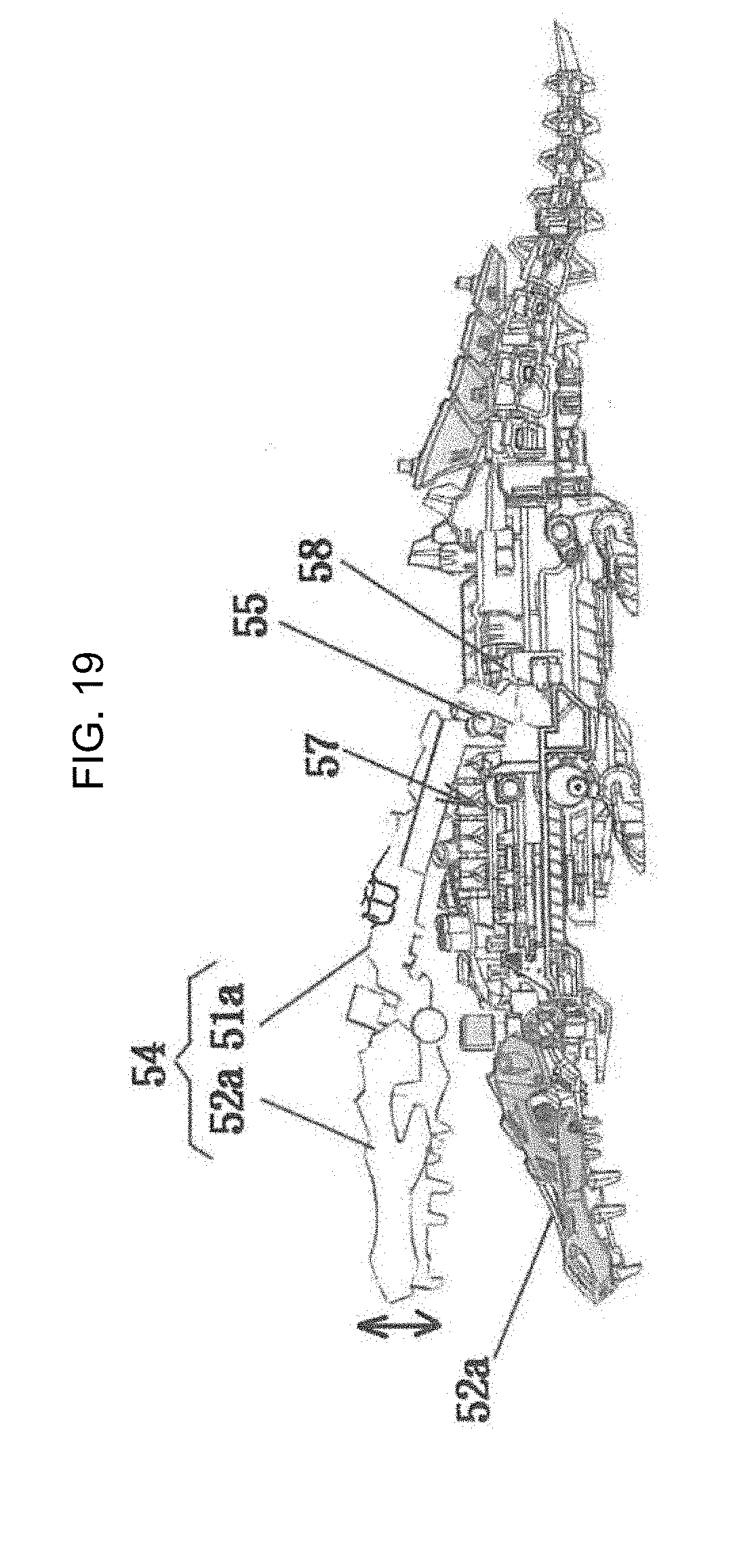
[0032] FIG. 19 is the side view showing an upper jaw operation mechanism of the form changing toy of the fourth embodiment.
DETAILED DESCRIPTION
[0033] In the following paragraphs, some embodiments of the invention will be described by way of example and not limitation. It should be understood based on this disclosure that various other modifications can be made by those in the art based on these illustrated embodiments.
[0034] Hereinafter, embodiments of a form changing toy according to the present invention will be described based on embodiments shown in the drawings. In the present specification and the scope of claims, when referring to "actuation device", it is a power source including a power transmission, an individual operation mechanism operating a predetermined operation part, and a power transmission mechanism which transmits power to the individual operation mechanism from the power transmission. Further, the phrase "movable parts" is defined as a part contributing to form changing in the operation parts. In certain embodiments, a switch is a part of the movable part to perform moving.
First Embodiment
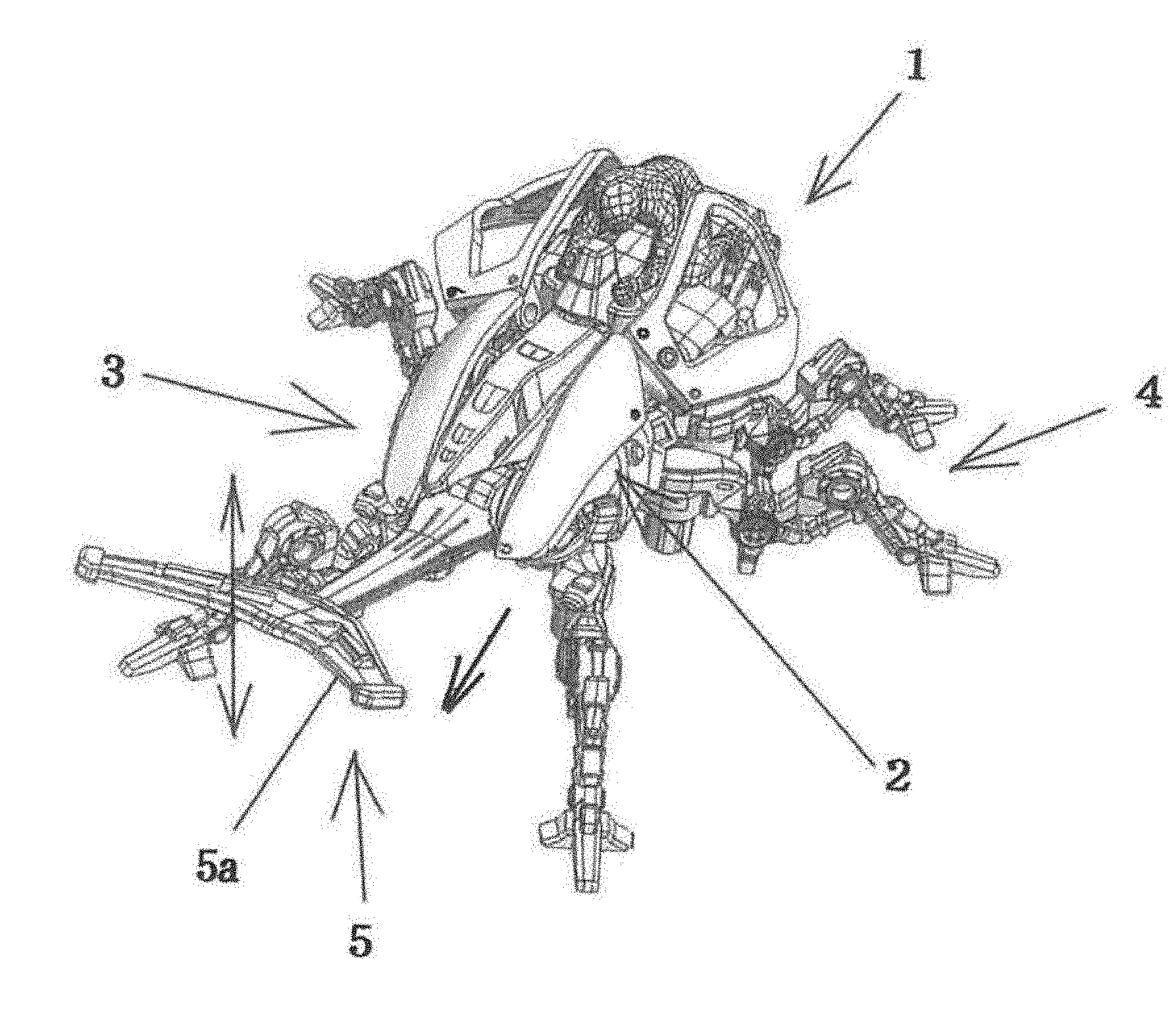
[0035] A form changing toy 1 shown in FIGS. 1 and 2 is shaped as a beetle, and includes components of a body part 2, a head part 3, leg parts 4, a horn part 5, etc. In the body part 2, a power spring is provided as a power transmission.
[0036] In the state shown in FIG. 1, a lower horn (operation part) of the head part 3 moves up and down by the power transmission, and the form changing toy 1 moves forward by operating the leg parts (operation parts) 4.
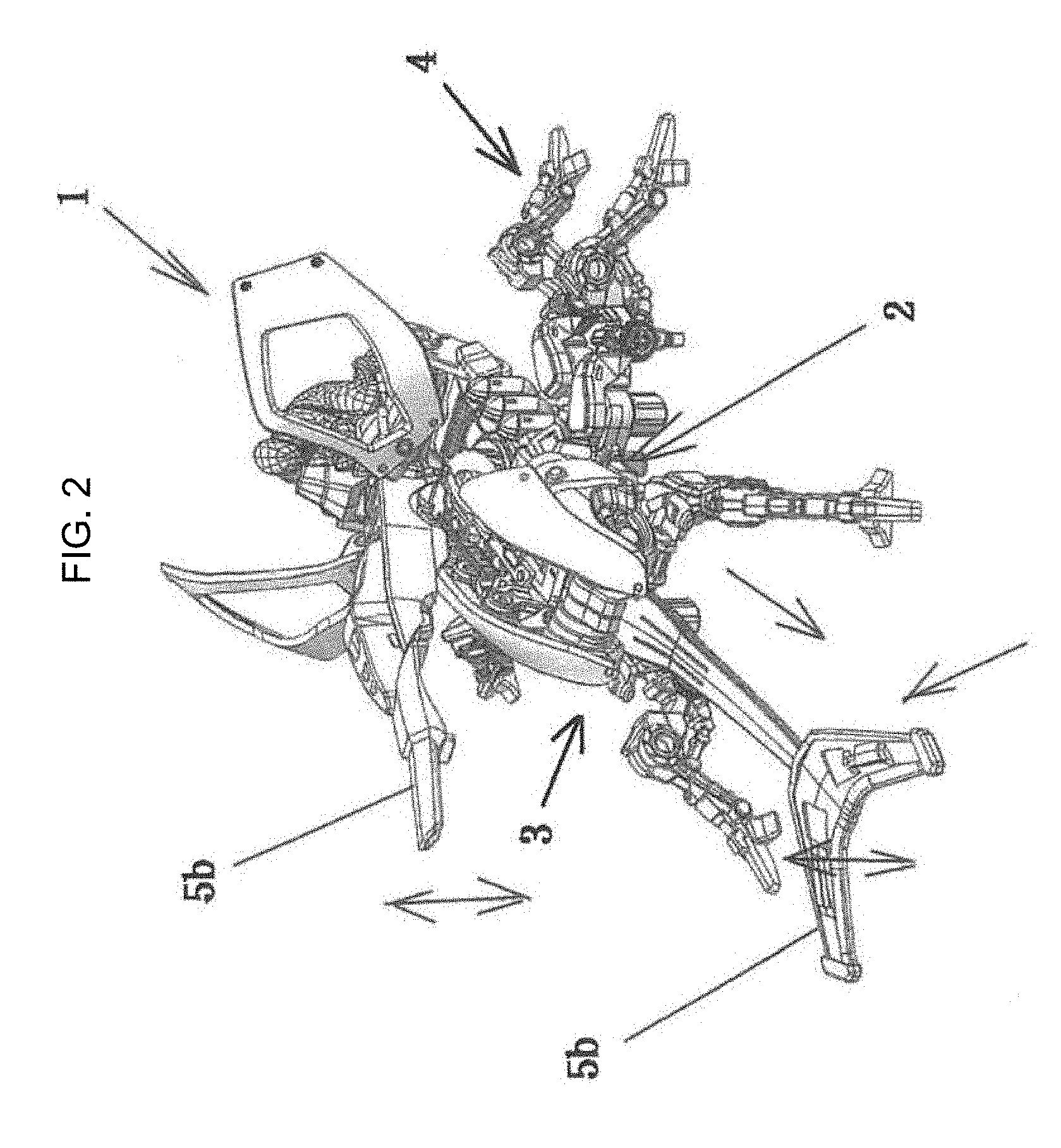
[0037] Further, as shown in FIG. 2, when the form is changed to manually expose an upper horn (movable part) 5b to the front side from the upper side part of the head part 3 and the body part 2 by hands, the form changing toy 1 moves forward by the leg parts 4 by the power transmission, and the upper horn 5b is moved up and down. In other words, the upper horn works as a switch to perform the movement in up and down.
[0038] FIG. 3 shows an operation mechanism 6 of the leg parts 4. The leg parts 4 are provided with right and left front legs 4a, right and left middle legs 4b, and right and left back legs 4c. Among these legs, the right and left middle legs 4b are secured to the body part 2. Further, the right and left front legs 4a are connected to each other by a connecting rod 6a, and further, the right and left back legs 4c are connected to each other by a connecting rod 6b. A middle part of each of the connecting rods 6a, 6b is rotatably supported to the body part 2 by shafts 6c, 6d.
[0039] Further, in a position off to the shaft 6c in the front side connecting rod 6a (e.g., left side position) and in a position off to the shaft 6d in the back side connecting rod 6b (e.g., right side position), a connecting rod 6e is rotatably connected. In a middle of the connecting rod 6e, a hole (not shown) is formed. On the other hand, in the body part 2, a gear 6f is rotatably supported, and an eccentric shaft (not shown) is projectingly provided in an eccentric position of the lower surface of the gear 6f The eccentric shaft is engaged to the hole of the connecting rod 6e.
[0040] Further, in the middle of the body part 2, a power spring (not shown) is provided as a power transmission. An output shaft 7 of the power spring extends in a vertical direction, and a gear 7a is securely provided in the output shaft 7. The gear 7a meshes with the aforementioned gear 6f.
[0041] In the leg parts 4, when the gear 7a rotates by the spring power, the gear 6f, which meshes with the gear 7a, rotates, and accordingly, the connecting rod 6e engaging with the eccentric shaft swings. With this structure, the front and back connecting rods 6a, 6b swing in opposite directions with respect to the shafts 6c and 6d. One of the right and left front legs 4a moves forward, and the other one of the right and left front legs 4a moves rearward. Further, the other one of the right and left back legs 4c moves forward and one of the right and left front legs moves rearward. Accordingly, the form changing toy 1 moves forward.
[0042] FIG. 4 shows an operation mechanism 8 of the lower horn 5a. The lower horn 5a is supported by a shaft 8a of the base end. The shaft 8a is rotatably supported to the frame of the head part 3, and the lower horn 5a is always urged downwardly by its own weight. In the shaft 8a, a bracket 8b is secured. On the other hand, in the upper end part of the output shaft 7, a disk cam 8c is securely fixed. In a position between the circumferential surface of the disk cam 8c and the aforementioned bracket 8b, an actuation piece 8d is arranged movably back and forth in the frame. The actuation piece 8d is always contacted to the circumferential surface of the disk cam 8c by the bracket 8b.
[0043] According to the operation mechanism 8 of the lower horn 5a, the disk cam 8c is rotated by the rotation of the output shaft 7, and when a ridge of the circumferential surface of the disk cam 8c is directed toward the actuation piece 8d, the actuation piece 8d is pressed by the disk cam 8c and it is moved forward. Then, the top end of the actuation piece 8d presses the bracket 8b, and the bracket 8b is rotated in a clockwise direction, and therefore, the lower horn 5a rotates upwardly. Further, when a valley of the circumferential surface of the disk cam 8c is moved toward the actuation piece 8b, the pressing force to the bracket 8b releases, so that the lower horn 5a is rotated in a counterclockwise direction by its own weight in FIG. 4, and the actuation piece 8b moves rearwardly while contacting with the circumferential surface of the disk cam 8c.
[0044] FIGS. 4 and 5 show an operation mechanism 9 of the upper horn 5b. FIG. 4 shows a state in which the upper horn 5b is stored inside an upper cover 2a constituting an upper part of the body part 2 and the head part 3. FIG. 5 shows a state in which the upper horn 5b projects to the front side.
[0045] The upper cover 2a is mounted on the body part 2 through the rotating body 2c. The rotating body 2c is rotatably mounted to the body part 2 by the shaft 2b. A slide body 9a integrated with the upper cover 2a is supported by the rotating body 2c in a movable manner in a front and back direction. The slide body 9a is formed in a u-shape in which the cross-section surface (cross-sectional surface perpendicular to the slide direction) releases downwardly. In the back end of the slide body 9a, a cam follower 9b which extends downwardly is formed. The disk cam 8c and the cam follower 9b are parts of an operation mechanism.
[0046] The base end of upper horn 5b is rotatably supported to the slide body 9a by the shaft 9c. The upper horn 5b is folded and stored in the slide body 9a as shown in FIG. 4. On the other hand, an end-face cam 9a is formed on the upper end surface of the output shaft 7. As described later, the end-face cam 9d is formed in a manner of being capable of contacting with the cam follower 9b of the slide body 9a.
[0047] As shown in FIG. 4, before changing form, the upper horn 5b is stored in the slide body 9a. This is a state in which the slide body 9a is pressed in a rear side, so that the cam follower 9b is located in a position separated from the end-face cam 9d.
[0048] When the upper cover 2a is opened upwardly, the upper horn 5b is rotated in a clockwise direction around the shaft 9c as a center. When the upper horn 5b is pulled out, the slide body 9a moves forward to the upper cover 2a. With this, as shown in FIG. 5, the cam follower 9b contacts with the end-face cam 9d. In this state, the integrated upper cover 2a, upper horn 5b, and slide body 9a (hereinafter referred to "upper horn assembly") maintain an opened state by the cam follower 9b.
[0049] The upper horn assembly moves up and down in accordance with the rotation of the end-face cam 9d. That is, when the cam follower 9b contacts with the ridge of the end-face cam 9d, as shown in FIG. 5, the upper horn assembly is positioned at the uppermost position. When the end-face cam 9d reaches the valley, the upper horn assembly is rotated in a counterclockwise direction around the shaft 2b as a center by its own weight so as to move downwardly.
Second Embodiment
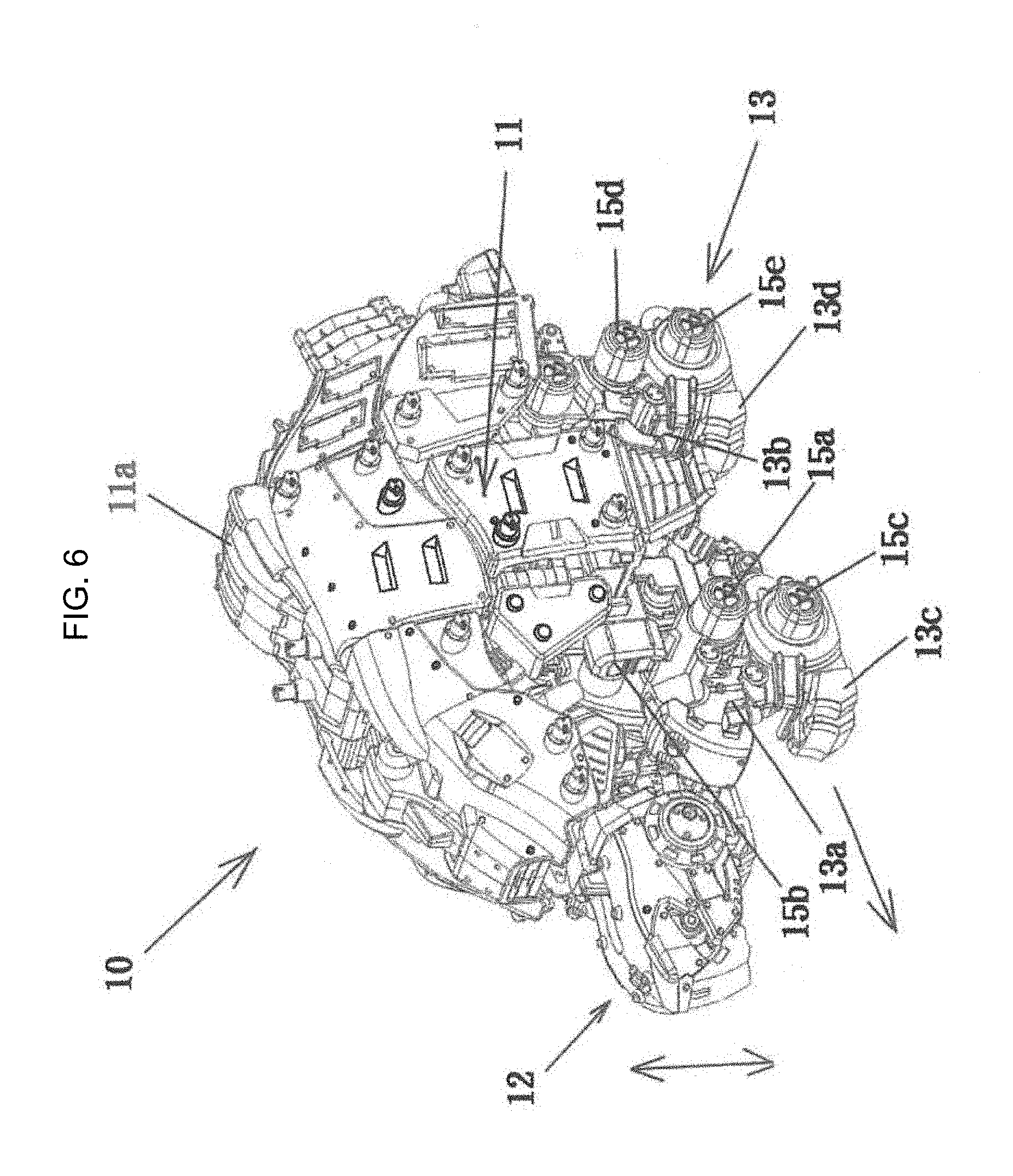
[0050] A form changing toy 10 shown in FIGS. 6 and 7 is shaped as a turtle, and includes components of a body part 11, a head part 12, and leg parts 13, etc., and a cannon 14 is stored inside the body part 11. Further, the form changing toy 10 is provided with a motor as a power source including a power transmission for the body part 11.
[0051] In a state shown in FIG. 6, in the form changing toy 10, by the power transmission, the leg parts (operation parts) 13 are operated so as to move forward, and the head part (operation part) 12 swings up and down.
[0052] Further, in the form changing toy 10, as shown in FIG. 7, the upper cover 11a which forms the upper side part of the body part 11, opens upwardly, and the top end of the cannon (movable part) 14 is exposed. When the form is changed by pulling the cannon 14 out in a forwardly obliquely upward direction, the leg parts 13 are operated by the power transmission so as to move forward, and the cannon 14 is connected to the power transmission, and therefore, the cannon 14 appears in the front and back direction.
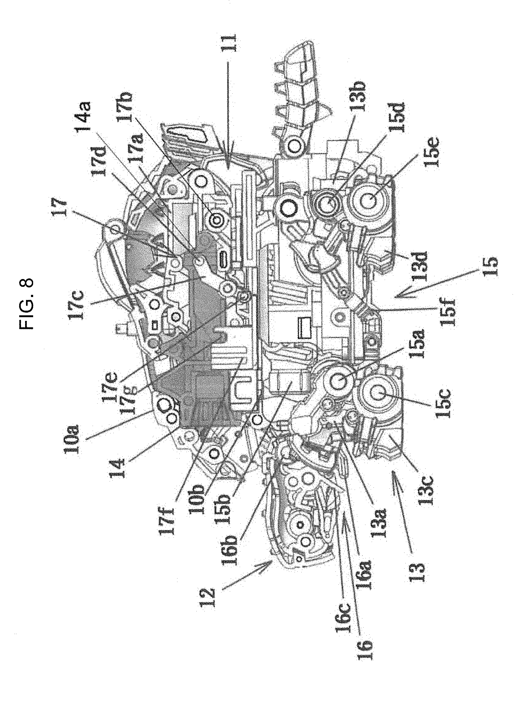
[0053] FIG. 8 shows an operation mechanism 15 of the leg parts 13. The leg parts 13 are provided with right and left front legs 13a and right and left back legs 13b.
[0054] A shaft hole 150a is formed on the back side of a middle part 15a of the right and left front legs 13a, and in the shaft hole, an eccentric shaft 151a of a rotation body (not shown) provided in the body part 13 is fitted in the shaft hole. Further, an elongated hole 150b is formed in the back surface of the upper end part 15b of the right and left front legs 13a, and the shaft 151b fixed in the body part 11 is inserted into the elongated hole 150a. Further, in the shaft 15c of the lower end part of the right and left front legs 13a, a grounding member 13c is rotatably supported (see FIG. 10).
[0055] On the other hand, a shaft hole 150d is formed in the back side of a middle part 15d of the right and left back legs 13b, and a shaft 151d fixed in the body part 11 is fitted into the shaft hole (see FIG. 10). Further, in the shaft 15d of the lower end part of the right and left back legs 13b, a grounding member 13d is rotatably supported.
[0056] Further, the lower part of the right and left front legs 13a and the upper part of the right and left back legs 13b are connected to each other by a connecting rod 15f.
[0057] According to the operation mechanism 15 of the leg parts 13, in the right and left front legs 13a, the front legs 13a swing through the eccentric shafts 151a by rotating the rotation body of the back side of the middle part 15a. Such movement of the front legs 13a transmits movement to the upper part of the back legs 13b through the connecting rod 15f, so that the back legs 13b swing around the shaft 15d as a center. Therefore, when the front legs 13a swing in the forward direction, the back legs 13b swing in the rearward direction.
[0058] By the way, in the operation mechanism 15 of the leg parts, the aforementioned eccentric shafts of the right and left front legs 13a are positioned with 180 degrees phase difference each other. That is, when the left front leg 13a swings in the forward direction, the right front leg 13a swings in the rearward direction. By repeating the movement, the turtle moves forward.
[0059] Further, the turtle 10 is provided with an operation mechanism 16 of the head part as shown in FIG. 8. In the operation mechanism 16, a protruding piece 16a is provided in the front part of the front leg 13a. On the other hand, the head part 12 is supported to the body part 11 by a shaft 16b so as to freely swing, and the tongue piece 16c is provided in the rear part of the head part 12. The tongue piece 16c of the head part 12 is positioned facing to the protruding piece 16a of the front legs 13a. When the front leg 13a swings forward, the protruding piece 16a further moves forward, and the protruding piece 16a presses a tongue piece 16c. Therefore, the head part 12 rotates upwardly (clockwise direction) around the shaft 16b as a center. The head part 12 moved upwardly rotates downwardly (counterclockwise direction) by its own weight while the front leg 13a moves rearwardly.
[0060] Further, the turtle 10 is provided with an operation mechanism 17 of the cannon. The cannon 14 is positioned in the upper part of the body part 11, and it is stored in a frame body 17a which is elongated in the front and back direction. The base end of the frame body 17 is rotatably supported by a shaft 17b, and the cannon 14 is slidably held in the frame body 17a. A lever 17c is rotatably supported in the bottom part of the frame body 17a. In the top end of the lever 17c, a cam follower 17d is arranged, and in the bottom end, an engagement roller 17e is arranged. The cam follower 17d is engaged with a groove 14a formed in a vertical direction in the rear end of the cannon 14.
[0061] On the other hand, in the body part 11 facing to the bottom wall of the frame body 17a, a slide body 17f which slides in the front and back direction is arranged. The slide body 17f is provided in the groove 17g which opens upwardly. The groove 17g is provided in a fitting manner with a projection 17e which will be described later.
[0062] Further, in the slide body 17f, as shown in FIG. 11, an opening 170e is formed, and in the opening 170e, an eccentric shaft 10d of a rotary roller 10c which is fixedly provided in a shaft 10b associated with the actuation device is inserted.
[0063] According to the operation mechanism 17 of the cannon, in FIG. 8, the frame body (upper cover) 17a opens upwardly (clockwise direction), and the cannon 14 is pulled out by hands. Then, as shown in FIG. 9, the engagement roller 17e of the lever 17c is fitted to the groove 17g of the slide body 17f. Therefore, after that, the lever 17c swings in accordance with the movement of the slide body 17f, and the cannon 14 appears through the cam follower 17d. This movement continues all the time while the turtle 10 moves forward.
Third Embodiment
[0064] A form changing toy 20 shown in FIGS. 12 and 13 is shaped as a dinosaur, and includes components of a body part 21, a head part 22, leg parts 23, and blade-shaped wings 24, etc. In the form changing toy 20, a motor as a power source including a power transmission is provided in the body part 21.
[0065] In a state shown in FIG. 13, in the form changing toy 20, the leg parts (operation parts) 23 are operated by the power transmission, and linking with the movement, upper jaw and jaw 22a (operation parts) additionally move up and down, and eyes 22b move front and back.
[0066] Further, as shown in FIG. 11, when the blade-shaped wings 24 arranged on the upper part of the body part 21 are rotated so as to overhang the wings forwardly and the form is changed, the blade-shaped wings (movable parts) 24 are additionally operated so as to swing by linking with the power transmission.
[0067] As shown in FIG. 14, the operation mechanism 25 of the leg parts 23 is provided with a connecting plate 27 which swings in an approximately vertical direction by receiving a rotary plate 26a linked with the power transmission of the motor, etc. through the gear train 26 and fitting to an eccentric shaft 26b of the rotary plate 26a through an elongated hole. Further, it is provided with a connecting body 28 which is linked with shafts 27a, 27b projectably provided to the connecting plate 27 through elongated holes 28a, 28b, and which is rotatably fitted to the eccentric shaft 26b. In the lower part of the connecting body 28, legs 28c are arranged.
[0068] According to the operation mechanism 25 of the leg parts, by a connecting plate 27, which is operated by the rotary plate 26a and the eccentric shaft 26b, and a connecting body 28, which is operated by the rotary movement of the eccentric shaft 26b, each leg 28c is separated from the ground and next, each leg moves forward and contacts on the ground again, so that it moves forward by such movements of alternatively raising the right and left legs.
[0069] The dinosaur 20 of this embodiment is provided with the operation mechanism 29 of the eyes. As shown in FIG. 15, the eyes 22b extend toward the upper part of the body part, and they are arranged on the top part of the slide body 29a which reciprocally moves in the front and back direction. In the middle of the slide body 29a, a groove cam 29b is formed. A pin 26d projectingly provided in the eccentric position of the final gear 26c of the gear train 26 is inserted into the groove cam 29b. By the pin 26d which connects with the actuation device and performs an eccentric rotation, the slide body 29a reciprocally moves front and back through the cam groove 29b, and the eyes 22b reciprocate.
[0070] In this dinosaur 20, an operation mechanism 30 of the jaw is provided. In the operation mechanism 30 of the jaw, the jaw 22a is rotatably supported to the head part 22 by the shaft 22c. The end part 22d of the jaw 22a is engaged with the slide body 29a as shown in FIG. 16.
[0071] Further, in the dinosaur 20, as shown in FIG. 15, the base ends of the blade-shaped wings 24 is rotatably supported in the both sides of the moving area of the slide body 29a, and projections 24a are formed in the base ends.
[0072] As shown in FIG. 14, the projections 24a are positioned separating from the slide body 29a when the blade-shaped wings 24 are stored in the rear side, and as shown in FIG. 15, when rotating toward the front side, they are engaged with the slide body 29a. Therefore, the blade-shaped wings 24 swing front and back in a travel direction in accordance with the movement of the slide body 29a.
Fourth Embodiment
[0073] According to another form of the present invention, as shown in FIG. 17, a form changing toy 50 is shaped as a crocodile, and includes components of a body part 51, a head part 52, and leg parts 53, etc. In the form changing toy 50, a motor as a power source including a power transmission is provided in the body part 51.
[0074] In the state shown in FIG. 17, the leg parts (operation parts) 53 are operated by the power transmission in the form changing toy 50.
[0075] Further, in this crocodile 50, an upper jaw 52a of the head part 52 and an upper part (back part) 51a of the body part 51 are integrated as shown in FIG. 19. In these assemblies 54, a rear end part is rotatably supported to the body part 51 by the shaft 55. By pulling the head part 52 forward, an upper jaw (movable part) 52a is largely opened and closed by linking with the operation mechanism of the leg parts 53.
[0076] The operation mechanism 55 of the leg parts has almost same structure as the leg part operation mechanism 15 shown in FIG. 7, and therefore, for the same parts, the same reference numerals are used and the explanation of these parts are omitted.
[0077] In the operation mechanism 55 of the leg parts, as shown in FIG. 18, the lower part of the right and left front legs 13a and the upper part of the right and left back legs 13b are connected to each other by a connecting plate 56.
[0078] By the operation mechanism 55 of the leg parts, the front legs 13a swing by an eccentric shaft 15a rotated by the power. Such movement of the front legs 13a transmits to the upper part of the back legs 13b through the connecting plate 56 and the back legs 13b swing around the shaft 15d as a center. Therefore, when the front legs 13a swing in the front direction, the back legs 13b swing in the rearward direction, and the crocodile 50 moves forward by repeating these movements.
[0079] Further, the crocodile 50 is provided with an operation mechanism 57 of the upper jaw. In the operation mechanism 57, as shown in FIG. 19, the slide body 58 which slides in the front and back direction is provided. The shaft 55 is arranged in the slide body 58. As shown in FIG. 19, the base end of the upper part assembly 54, which is provided with the upper jaw 52a of the head part 52 and the back part 51a of the body part 51, is rotatably secured to the shaft 55.
[0080] In the upper part assembly 54, in a normal state as shown in FIG. 17, the slide body 58 (FIG. 19) is positioned in the rear side of the body part and is mounted on the body part 51.
[0081] The slide body 58 moves forward by pulling the head part 52 forward. Then, the base end of the upper part assembly 54 is engaged with the connecting plate 56.
[0082] In such way, when the base end of the upper part assembly 54 is engaged with the connecting plate 56, after that, it is operated by the movement of the connecting plate 56, so that the upper part assembly 54 is rotated upwardly (clockwise direction) around the shaft 55.
[0083] The rotation amount which rotates in the upward direction of the upper part assembly 54 is determined by the pressing amount of the connecting plate 56. Therefore, with such consideration, an appropriate position of the engagement position between the upper part assembly 54 and the connecting plate 56 is set.
Effect of the Invention
[0084] According to the form changing toy of the present invention, by operating movable parts manually, the movable parts can be actuated, so that running toys full of variation can be obtained.
[0085] The embodiments of the present invention were described above, but the present invention is not limited to the aforementioned embodiments, and needless to say, various modifications may be made within the scope that does not depart from the essential point of the present invention.
[0086] For example, in the form changing toys of the aforementioned embodiments, the shapes of beetle, turtle, dinosaur, stag beetle, crocodile were described, but it may be other shapes of living things or imaginary living things. Further, as the manual operation components, a horn, a cannon, wings, and an upper jaw were described, but it may be other components.
[0087] The terms and descriptions used herein are used only for explanatory purposes and the present invention is not limited to them. Accordingly, the present invention allows various design-changes falling within the claimed scope of the present invention.
[0088] While the present invention may be embodied in many different forms, a number of illustrative embodiments are described herein with the understanding that the present disclosure is to be considered as providing examples of the principles of the invention and such examples are not intended to limit the invention to preferred embodiments described herein and/or illustrated herein.
[0089] While illustrative embodiments of the invention have been described herein, the present invention is not limited to the various preferred embodiments described herein, but includes any and all embodiments having equivalent elements, modifications, omissions, combinations (e.g., of aspects across various embodiments), adaptations and/or alterations as would be appreciated by those in the art based on the present disclosure. The limitations in the claims are to be interpreted broadly based on the language employed in the claims and not limited to examples described in the present specification or during the prosecution of the application, which examples are to be construed as non-exclusive. For example, in the present disclosure, the term "preferably" is non-exclusive and means "preferably, but not limited to." In this disclosure and during the prosecution of this application, the terminology "present invention" or "invention" is meant as a non-specific, general reference and may be used as a reference to one or more aspects within the present disclosure. The language present invention or invention should not be improperly interpreted as an identification of criticality, should not be improperly interpreted as applying across all aspects or embodiments (i.e., it should be understood that the present invention has a number of aspects and embodiments), and should not be improperly interpreted as limiting the scope of the application or claims. In this disclosure and during the prosecution of this application, the terminology "embodiment" can be used to describe any aspect, feature, process or step, any combination thereof, and/or any portion thereof, etc. In some examples, various embodiments may include overlapping features.
* * * * *
D00000
D00001
D00002
D00003
D00004
D00005
D00006
D00007
D00008
D00009
D00010
D00011
D00012

D00013

D00014

D00015

D00016

D00017

D00018
XML
uspto.report is an independent third-party trademark research tool that is not affiliated, endorsed, or sponsored by the United States Patent and Trademark Office (USPTO) or any other governmental organization. The information provided by uspto.report is based on publicly available data at the time of writing and is intended for informational purposes only.
While we strive to provide accurate and up-to-date information, we do not guarantee the accuracy, completeness, reliability, or suitability of the information displayed on this site. The use of this site is at your own risk. Any reliance you place on such information is therefore strictly at your own risk.
All official trademark data, including owner information, should be verified by visiting the official USPTO website at www.uspto.gov. This site is not intended to replace professional legal advice and should not be used as a substitute for consulting with a legal professional who is knowledgeable about trademark law.