Form Changing Toy
NAKASE; Takashi ; et al.
U.S. patent application number 16/196646 was filed with the patent office on 2019-08-29 for form changing toy. This patent application is currently assigned to TOMY Company, Ltd.. The applicant listed for this patent is TOMY Company, Ltd.. Invention is credited to Akiko IKOMA, Shigeru KANAUCHI, Shu KATAYAMA, Takashi NAKASE, Mitsutoshi TOKUYAMA, Haruhisa UJITA, Hiroyuki WATANABE.
| Application Number | 20190262733 16/196646 |
| Document ID | / |
| Family ID | 67406095 |
| Filed Date | 2019-08-29 |


| United States Patent Application | 20190262733 |
| Kind Code | A1 |
| NAKASE; Takashi ; et al. | August 29, 2019 |
FORM CHANGING TOY
Abstract
A form changing toy includes a power source, a power transmission mechanism, an operation part, a switch, a movable part, a locking mechanism, and a connecting part. The operation part is configured to perform a predetermined operation by the power. The switch is configured to be moved between a first position to a second position, and being urged to the second position. The locking mechanism is configured to lock the movable part at the first position when the movable part is manually moved from the second position to the first position, and is configured to release locking by the power when the predetermined operation continues. The connecting mechanism is configured to operate the movable part by connecting the movable part and either one of the power transmission mechanism and the operation part when the movable part moves to the second position.
| Inventors: | NAKASE; Takashi; (Tokyo, JP) ; KATAYAMA; Shu; (Tokyo, JP) ; IKOMA; Akiko; (Tokyo, JP) ; TOKUYAMA; Mitsutoshi; (Tokyo, JP) ; KANAUCHI; Shigeru; (Tokyo, JP) ; WATANABE; Hiroyuki; (Tokyo, JP) ; UJITA; Haruhisa; (Tokyo, JP) | ||||||||||
| Applicant: |
|
||||||||||
|---|---|---|---|---|---|---|---|---|---|---|---|
| Assignee: | TOMY Company, Ltd. Tokyo JP |
||||||||||
| Family ID: | 67406095 | ||||||||||
| Appl. No.: | 16/196646 | ||||||||||
| Filed: | November 20, 2018 |
| Current U.S. Class: | 1/1 |
| Current CPC Class: | A63H 29/24 20130101; A63H 33/003 20130101; A63H 29/22 20130101; A63H 31/00 20130101; A63H 13/005 20130101 |
| International Class: | A63H 13/00 20060101 A63H013/00; A63H 29/22 20060101 A63H029/22; A63H 29/24 20060101 A63H029/24 |
Foreign Application Data
| Date | Code | Application Number |
|---|---|---|
| Feb 26, 2018 | JP | 2018-032404 |
Claims
1. A form changing toy comprising: a power source being configured to provide power; a power transmission mechanism being configured to transmit the power; an operation part being configured to perform a predetermined operation by the power via the power transmission mechanism; a switch being configured to move between a first position to a second position, and being urged to the second position; a movable part; a locking mechanism being configured to lock the movable part at the first position when the movable part is manually moved from the second position to the first position, and configured to release locking by the power when the predetermined operation continues; and a connecting mechanism being configured to operate the movable part by connecting the movable part and either one of the power transmission mechanism and the operation part when the movable part moves to the second position.
2. The form changing toy according to claim 1, further comprising: an urging member being configured to urge the movable part to the second position.
3. The form changing toy according to claim 1, further comprising four legs including two front legs and two back legs, wherein the movable part is a jaw, the operation part is configured to connect the front legs and the back legs, and to transmit the power from the front legs to the back legs or from the back legs to the front legs, and a part of the jaw is operated by an operation of the connecting body when the switch is at the second position.
4. The form changing toy according to claim 3, wherein the movable part includes a body part and a shaft, and is arranged to swing front and back around the shaft provided in the body part, the movable body is integrally formed with the switch, the movable body is located in a position along the body part when the switch is at the first position, and the movable body is located in a position separate from the body part when the switch is at the second position so as to swing front and back.
5. The form changing toy according to claim 1, wherein a first form of the form changing toy when the switch is at the first position is different from a second form of the form changing toy when the switch is at the second position.
Description
CROSS-REFERENCE TO THE RELATED APPLICATION
[0001] The present application claims priority under 35 U.S.C. 119 to Japanese Patent Application No. 2018-032404 filed on Feb. 26, 2018. The contents of this application are incorporated herein by reference in their entirety.
BACKGROUND OF THE INVENTION
Filed of the Invention
[0002] The present invention relates to a form changing toy.
Description of Related Art
[0003] It is a robot toy capable of mutually changing from the first form as a doll form to the second form, which is different from the first form, automatically or by a remote control. Further, it is well-known to provide a deforming means which changes from the first form to the second form, a deforming means which changes from the second form to the first form, and a moving means which is movable in any of the first form and the second form (please see Japanese Patent Application Publication No. 2014-144211).
[0004] However, in the aforementioned form changing toy, from a view point of movements, the toy only runs before and after changing the form, so that there was a problem of lacking interest factors.
[0005] The description herein of advantages and disadvantages of various features, embodiments, methods, and apparatus disclosed in other publications is in no way intended to limit the present invention. For example, certain features of the preferred described embodiments of the invention may be capable of overcoming certain disadvantages and/or providing certain advantages, such as, e.g., disadvantages and/or advantages discussed herein, while retaining some or all of the features, embodiments, methods, and apparatus disclosed therein.
SUMMARY OF THE INVENTION
[0006] The disclosed embodiments of the present invention have been developed in view of the above-mentioned and/or other problems in the related art. The disclosed embodiments of the present invention can significantly improve upon existing methods and/or apparatuses.
[0007] An object of the present invention is to provide a form changing toy with interest factors such that other operations are added after changing form.
[0008] In some aspects of the invention, a form changing toy includes a power source, a power transmission mechanism, an operation part, a switch, a movable part, a locking mechanism, and a connecting part. The power source is configured to provide power. The power transmission mechanism is configured to transmit the power. The operation part is configured to perform a predetermined operation by the power via the power transmission mechanism. The switch is configured to be moved between a first position to a second position, and being urged to the second position. The locking mechanism is configured to lock the movable part at the first position when the movable part is manually moved from the second position to the first position, and is configured to release locking by the power when the predetermined operation continues. The connecting mechanism is configured to operate the movable part by connecting the movable part and either one of the power transmission mechanism and the operation part when the movable part moves to the second position.
[0009] In some aspects of the invention, the form changing toy further includes an urging member being configured to urge the movable part to the second position.
[0010] In some aspects of the invention, the form changing toy includes four legs including two front legs and two back legs, wherein the movable part is a jaw, the operation part is configured to connect the front legs and the back legs, and to transmit the power from the front legs to the back legs or from the back legs to the front legs, and a part of the jaw is operated by an operation of the connecting body when the switch is at the second position.
[0011] In some aspects of the invention, the movable part includes a body part and a shaft, and is arranged to swing front and back around the shaft provided in the body part. The movable body is integrally formed with the switch. The movable body is located in a position along the body part when the switch is at the first position. The movable body is located in a position separate from the body part when the switch is at the second position so as to swing front and back.
[0012] In some aspects of the invention, a first form of the form changing toy when the switch is at the first position is different from a second form of the form changing toy when the switch is at the second position.
[0013] The above and/or other aspects, features and/or advantages of various embodiments will be further appreciated in view of the following description in conjunction with the accompanying figures. Various embodiments can include and/or exclude different aspects, features and/or advantages where applicable. In addition, various embodiments can combine one or more aspect or feature of other embodiments where applicable. The descriptions of aspects, features and/or advantages of particular embodiments should not be construed as limiting other embodiments or the claims. In the drawings, the size and relative sizes of layers and regions may be exaggerated for clarity. Like numbers refer to like elements throughout. The terminology used herein is for the purpose of describing particular embodiments only and is not intended to be limiting of the invention. As used herein, the singular forms "a", "an" and "the" are intended to include the plural forms as well, unless the context clearly indicates otherwise. As used herein, the term "and/or" includes any and all combinations of one or more of the associated listed items and may be abbreviated as "/". It will be understood that, although the terms first, second, etc. may be used herein to describe various elements, these elements should not be limited by these terms. Unless indicated otherwise, these terms are only used to distinguish one element from another. For example, a first object could be termed a second object, and, similarly, a second object could be termed a first object without departing from the teachings of the disclosure. It will be further understood that the terms "comprises" and/or "comprising," or "includes" and/or "including" when used in this specification, specify the presence of stated features, regions, integers, steps, operations, elements, and/or components, but do not preclude the presence or addition of one or more other features, regions, integers, steps, operations, elements, components, and/or groups thereof. It will be understood that when an element is referred to as being "connected" or "coupled" to or "on" another element, it can be directly connected or coupled to or on the other element or intervening elements may be present. In contrast, when an element is referred to as being "directly connected" or "directly coupled" to another element, there are no intervening elements present. Other words used to describe the relationship between elements should be interpreted in a like fashion (e.g., "between" versus "directly between," "adjacent" versus "directly adjacent," etc.). However, the term "contact," as used herein refers to direct contact (i.e., touching) unless the context indicates otherwise. Terms such as "same," "planar," or "coplanar," as used herein when referring to orientation, layout, location, shapes, sizes, amounts, or other measures do not necessarily mean an exactly identical orientation, layout, location, shape, size, amount, or other measure, but are intended to encompass nearly identical orientation, layout, location, shapes, sizes, amounts, or other measures within acceptable variations that may occur, for example, due to manufacturing processes. The term "substantially" may be used herein to reflect this meaning. Unless otherwise defined, all terms (including technical and scientific terms) used herein have the same meaning as commonly understood by one of ordinary skill in the art to which this disclosure belongs. It will be further understood that terms, such as those defined in commonly used dictionaries, should be interpreted as having a meaning that is consistent with their meaning in the context of the relevant art and/or the present application, and will not be interpreted in an idealized or overly formal sense unless expressly so defined herein.
BRIEF DESCRIPTION OF THE DRAWINGS
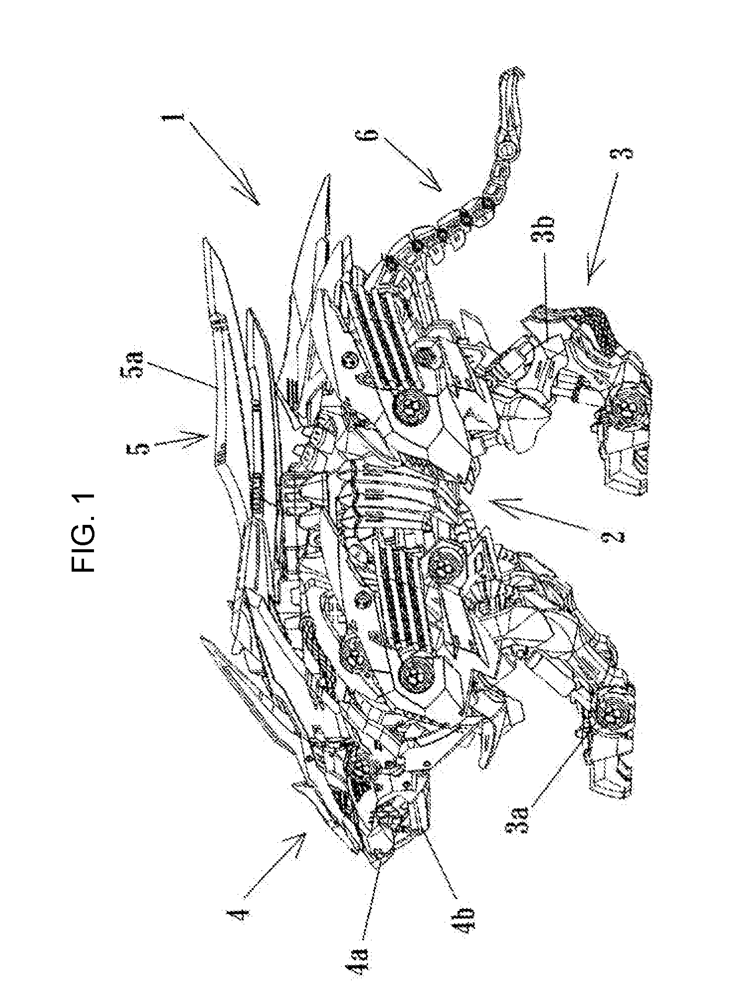
[0014] FIG. 1 is a side view showing a form of a form changing toy of an embodiment before changing the form;
[0015] FIG. 2 is a side view showing a form of the form changing toy after changing the form;
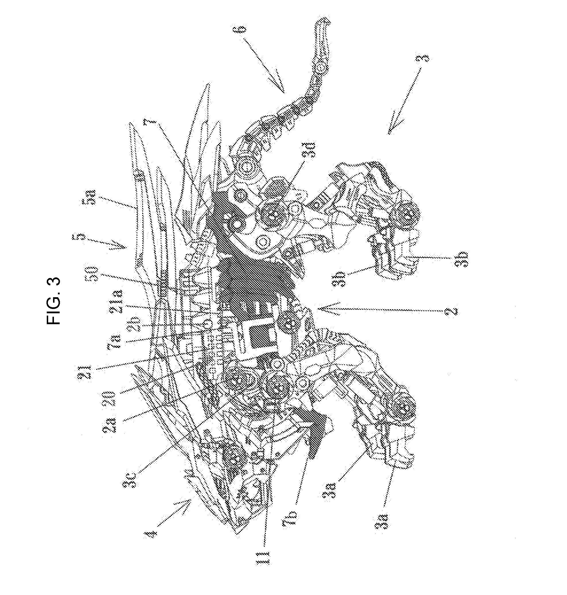
[0016] FIG. 3 is a side view showing the form changing toy according to the present invention;
[0017] FIG. 4 is a side view showing an operation mechanism of the form changing toy;
[0018] FIG. 5 is a partial enlarged perspective view showing a part of the operation mechanism of FIG. 4;
[0019] FIG. 6 is a partial enlarged perspective view showing a part of the operation mechanism of FIG. 4;
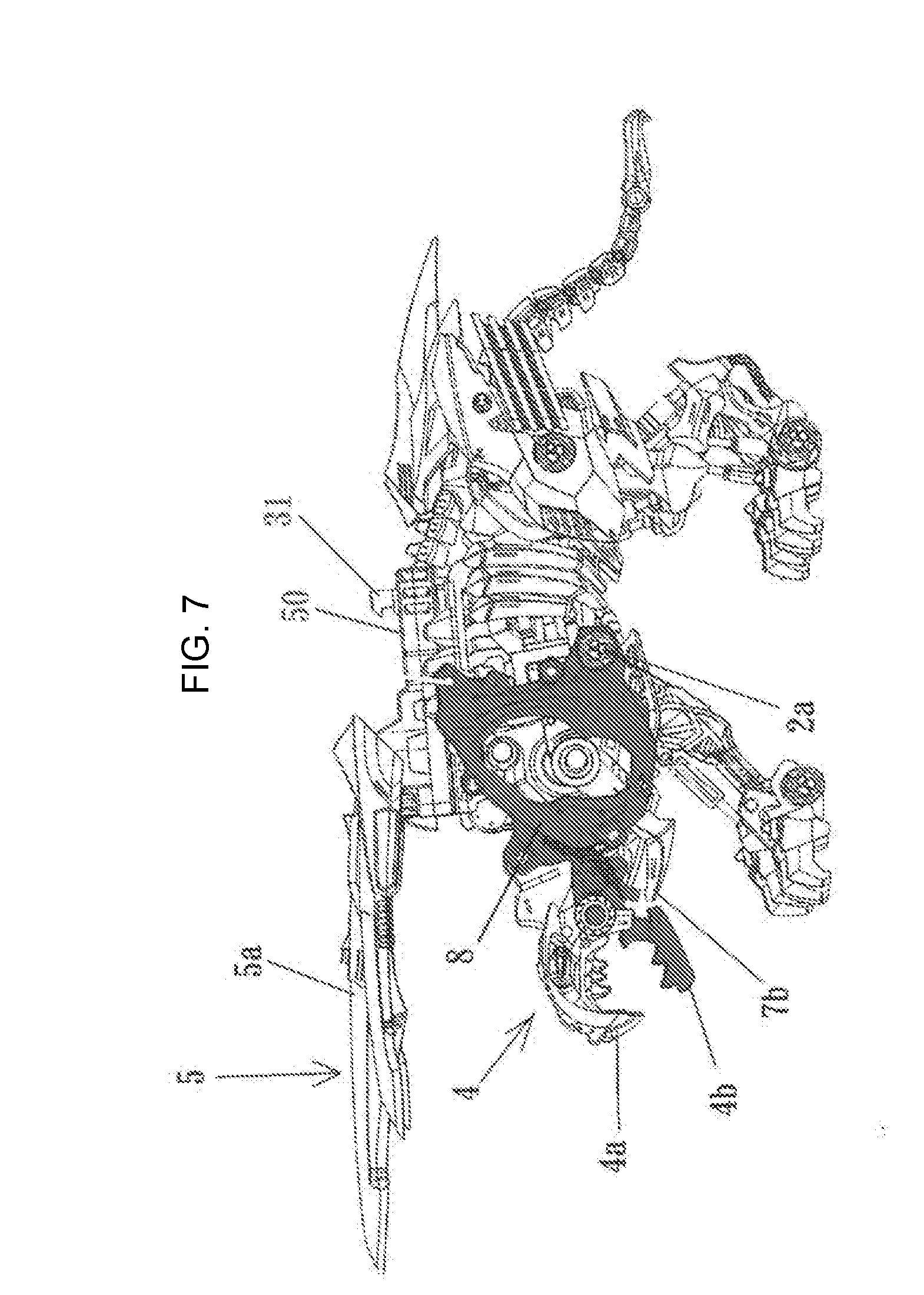
[0020] FIG. 7 is a side view showing a part of the operation mechanism of FIG. 4;
[0021] FIG. 8 is a partial enlarged cross-sectional view showing a power system; and
[0022] FIG. 9 is a partial enlarged perspective view showing a part of the operation mechanism of FIG. 4.
DETAILED DESCRIPTION
[0023] In the following paragraphs, some embodiments of the invention will be described by way of example and not limitation. It should be understood based on this disclosure that various other modifications can be made by those in the art based on these illustrated embodiments.
[0024] Hereinafter, embodiments of a form changing toy according to the present invention will be described based on embodiments shown in the drawings. In the present specification and the scope of claims, a switch is a part of the movable part to perform moving.
[0025] As shown in FIGS. 1 and 2, the form changing toy 1 includes components of a body part 2, leg parts 3, a head part 4, a horn part 5, a tail part 6, etc. In the state shown in FIG. 1, the leg parts 3 are operated by a power source, and the form changing toy 1 moves forward while the head part 4 is continuously inclined downwardly. Then, at the point after a predetermined number of steps which the form changing to 1 takes, the horn part 5 projects forward, and when the head part 4 reaches the lower end, as shown in FIG. 2, an upper jaw 4a, which is a part of the head part 4, swings vertically, so that while the horn part 4 swings vertically and the upper jaw 4a swings vertically, it moves forward.
[0026] As shown in FIG. 1, the leg parts 3 are constituted with right and left front legs 3a, and right and left back legs 3b. As shown in FIG. 3, in the right and left front legs 3a, the middle part is rotatably supported by an eccentric shaft 11 of a power system 10, and the upper end part is rotatably supported by the shaft 2a, which is secured to the body part 2 through an elongated hole 3. On the other hand, in the right and left back legs 3b, the middle part is rotatably supported to the body part 2 by a shaft 3d. The middle part of the right and left front legs 3a and the upper part of the right and left back legs 3b are connected each other by a connecting body 7.
[0027] In the leg parts 3, the front legs 3a swing by the eccentric shaft 11 which rotates by the power. The movement of the front legs 3a is transmitted to the upper part of the back legs 3b through the connecting body 7, and the back legs 3a swing around the shaft 3d as a center. In this case, when the front leg 3a swings forward, the back leg 3b swings rearward.
[0028] In the left and right sides of the form changing toy 1, the left and right eccentric shafts 11 are positioned with 180 degree phase difference each other. With this structure, when the left front leg 3a swings forward, the right front leg 3a swing rearward. By repeating this movement, the form changing toy 1 moves forward.
[0029] As shown in FIG. 4, the head part 4 is supported by the body part 2 through a connecting body 8. The connecting body 8 has an approximately triangular shape, and one corner part is rotatably arranged to the body part 2 by the shaft 2a, and in the inside of the other one corner part, an elongated hole (not shown) is formed. In the elongated hole, a shaft 2b is inserted and is rotatably supported by a slider 21 which will be described later. In the other remaining corner part of the connecting body 8, a lower jaw 4b which is part of the head part 4 is formed.
[0030] The head part 4 is continuously lowered by a head part operation mechanism 20. As shown in FIG. 3, the head part operation mechanism 20 is provided with the slider 21 which is positioned in the upper side of the connecting body 7. The slider 21 is operated in the front and back direction. On the lower part of the slider 21, a serrated ratchet tooth 21a is formed. On the other hand, a ratchet claw 7a is formed on the connecting body 7. On the one side of the slider 21, as mentioned above, the connecting body 8 is rotatably supported by the shaft 2b.
[0031] As shown in FIGS. 5 and 6, the slider 21 is formed over both sides of the body part 2, and on a plate 21b which is the part over both sides of the body part 2, an elongated hole 21c is formed and an elastic piece 21d is formed in a projecting manner in the elongated hole 21c. On the other hand, on the upper surface of the body part 2, a projection part 2c is formed. On the side surface of the projection part 2c, a plurality of recess parts 2d is formed. The slider 21 is arranged in the body part 2 by fitting the elongated hole 21c to the projection part 2c of the body part 2, and the top end of the elastic piece 21d presses and contacts to the recess parts 2d of the projection part 2c.
[0032] According to the head part operation mechanism 20 with such configuration, the ratchet claw 7a contacts to the ratchet tooth 21a of the slider 21 in accordance with the operation of the connecting body 7, and the slider 21 moves forward by an amount of one tooth only. Then the connecting body 8 is rotated around the shaft 2a through the shaft 2b, and the head part 3 is lowered by the amount of one tooth. The top end of the elastic piece 21d is fitted to the next recess part 2d, and the position of the slider 21 is determined. By repeating such operation, the head part 4 continuously moves downward. When the head part 4 reaches the lowest point, the top end 7b of the connecting body 7 enters in the moving area and the upper jaw 4a is pushed upward by the top end 7b of the connecting body 7. When the top end 7b of the connecting body 7 is retreated, in accordance with that, the upper jaw 4a is lowered by its own weight so as to close the mouth.
[0033] Further, in the form changing toy 1, a unit case 50 is detachably mounted to the body part 2. The unit case 50 is provided with a horn locking mechanism 30 which locks a horn 50a in the back side in a laying manner.
[0034] In the unit case 50, as shown in FIG. 6, the base part of the horn 5a is rotatably supported to the bracket 2e projecting to the unit case 50. The horn 5a is urged by spring (not shown) so as to rotate toward the front side. The horn 5a is locked by a hook 31, which is provided in the unit case 50, and is restrained to the body part 2. The hook 31 is urged in a locking direction by the spring, and the lower end part is stored in a hole 21e which is formed on the slider 21. When the slider 21 moves forward, the lower part of the hook 31 is rotated by a rear end wall (not shown) of the hole 21e, and therefore, the hook 31 becomes a release state.
[0035] Further, the form changing toy 1 is provided with an operation mechanism 40 in which the horn 5a swings in a vertical direction in a state of projecting the horn 5a forward as shown in FIG. 2. The operation mechanism 40 is provided with a slide body 41 which slides in a front and back direction by the gear of the power system 10 which will be described later.
[0036] As shown in FIG. 9, on the upper front end of the slide body 41, a projection 42 is formed. The projection 42 responses to the rear end 5b of the horn 5a. In a state in which the slide body 41 slides forward, the projection 42 contacts to the rear end 5b of the horn 5a, so that the top end of the horn 5a moves upward.
[0037] The movement of the slide body 41 in the front and back direction is performed by the gear of the power system 10. As shown in FIG. 8, in the power system 10, the large gear 12a is rotated by a motor (not shown), and a small gear (not shown) fastened in the same shaft meshes with a large gear 13a. The large gear 13a meshes with a crown gear 14a. In the crown gear 14a, a small gear 14b is provided. On the other hand, an input gear 51 is rotatably supported in the unit case 50, and a gear 52 which meshes with the input gear 51 is rotatably supported.
[0038] When the unit case 50 is set to the body part 2, the input gear 51 meshes with the gear 14b of the body part 2.
[0039] The gear 52 is stored inside the unit case 50. A pin 52a is disposed in the upper surface of the gear 52. On the other hand, in the slide body 41, a cam (not shown) is formed. The slide body 41 moves in the front and back direction by the revolution of the pin 52a in accordance with the rotation of the gear 52. When the slide body 41 moves forward, the projection 42 contacts to the rear end 5b of the horn 5a.
[0040] In the power system 10, the large gear 13a and the small gear 13b on the same shaft mesh with a crank gear 15a. The power is transmitted to the crank shaft. With this structure, the front legs 3a are operated.
[0041] In the form changing toy 1, the ratchet claw 7a is operated by the movement of the connecting body 7 which operates the legs 3, and therefore, the slider 21 moves forward. When the slider 21 moves a few pitches, the hook 31 is operated by the rear end of the hole 21e which is formed in the plate 21b, and the restraint of the horn 5a releases. Then, the horn 5a rotates forward by the urging force of the spring. During the period, the leg parts 3 are continuously operated by the power.
[0042] After that, the horn 5a is operated by the projection 42 of the slide body 41 which is operated by the revolution of the pin 62a of the gear 52. In the operation state of the horn 5a at that time, depending on the shape of the cam formed in the slide body 41, it can be set in various operation modes such that for example, the horn 5a gradually moves upward and moves down sharply, etc.
[0043] During walking of the form changing toy 1, the slider 21 intermittently moves forward, and the connecting body 8 is intermittently rotated through the shaft 2b. That is, the head part 4 intermittently moves downward. Further, when the head part 4 reaches the lower end, since the top end 7a of the connecting body 7 hits the base end of the upper jaw 4a of the head part 4, the upper jaw 4a rotates upward, and therefore, it opens with respect to the lower jaw 4b.
[0044] In the form changing toy 1 of the aforementioned embodiment, the leg parts 3 always walk, and the head part 4 is continuously lowered from the beginning of the walk. The horn 5a is deployed forward when it walks few steps, and next, the horn 5a keeps swinging vertically. When the head part 4 reaches the lowest point, the mouth of the head part 4 opens and closes. After that, the horn 5a moves vertically, it keeps walking while opening and closing the mouth of the head part 4. However, the timing of these operations can be changed appropriately. For example, the deploying timing of the horn 5a can be changed by changing the interval between the rear end wall 21f of the hole 21e and the hook 31. By changing the shape of the cam which is engaged with the pin of the gear 52, the swinging mode of the horn 5a can be changed.
[0045] In the aforementioned embodiment, as the component parts, the horn 5a, the head part 4, and the upper jaw 4a were shown, but other component parts can be employed.
[0046] In the aforementioned embodiment, the unit case 50 which is provided with the horn part 5 is mounted on the body part 2, but the unit case 50 which is provided with other component parts can be mounted.
Effect of the Invention
[0047] When the operation of the actuation device or the operation part continues, the movable part is changed from the first position to the second position, and a predetermined operation is performed, so that a form changing toy having unexpectedness and interesting factors can be realized.
[0048] Since the movable part can be moved from the first position to the second position by a predetermined urging force, a form changing toy with a simple structure can be realized.
[0049] According to the third means, when the movable toy is changed from the first position to the second position, a part of the jaw can be operated by the connecting body, so that a form changing toy with a simple structure can be realized.
[0050] According to the fourth means, when the movable toy is changed from the first position to the second position, it performs a predetermined operation in a position separated from the body part, so that a form changing toy with unexpectedness can be realized.
[0051] While the present invention may be embodied in many different forms, a number of illustrative embodiments are described herein with the understanding that the present disclosure is to be considered as providing examples of the principles of the invention and such examples are not intended to limit the invention to preferred embodiments described herein and/or illustrated herein.
[0052] While illustrative embodiments of the invention have been described herein, the present invention is not limited to the various preferred embodiments described herein, but includes any and all embodiments having equivalent elements, modifications, omissions, combinations (e.g., of aspects across various embodiments), adaptations and/or alterations as would be appreciated by those in the art based on the present disclosure. The limitations in the claims are to be interpreted broadly based on the language employed in the claims and not limited to examples described in the present specification or during the prosecution of the application, which examples are to be construed as non-exclusive. For example, in the present disclosure, the term "preferably" is non-exclusive and means "preferably, but not limited to." In this disclosure and during the prosecution of this application, the terminology "present invention" or "invention" is meant as a non-specific, general reference and may be used as a reference to one or more aspects within the present disclosure. The language present invention or invention should not be improperly interpreted as an identification of criticality, should not be improperly interpreted as applying across all aspects or embodiments (i.e., it should be understood that the present invention has a number of aspects and embodiments), and should not be improperly interpreted as limiting the scope of the application or claims. In this disclosure and during the prosecution of this application, the terminology "embodiment" can be used to describe any aspect, feature, process or step, any combination thereof, and/or any portion thereof, etc. In some examples, various embodiments may include overlapping features.
* * * * *
D00000
D00001
D00002
D00003
D00004
D00005
D00006
D00007
D00008
XML
uspto.report is an independent third-party trademark research tool that is not affiliated, endorsed, or sponsored by the United States Patent and Trademark Office (USPTO) or any other governmental organization. The information provided by uspto.report is based on publicly available data at the time of writing and is intended for informational purposes only.
While we strive to provide accurate and up-to-date information, we do not guarantee the accuracy, completeness, reliability, or suitability of the information displayed on this site. The use of this site is at your own risk. Any reliance you place on such information is therefore strictly at your own risk.
All official trademark data, including owner information, should be verified by visiting the official USPTO website at www.uspto.gov. This site is not intended to replace professional legal advice and should not be used as a substitute for consulting with a legal professional who is knowledgeable about trademark law.