Device and Method for the Ablation of Fibrin Sheath Formation on a Venous Catheter
Hobbs; Eamonn ; et al.
U.S. patent application number 16/406646 was filed with the patent office on 2019-08-29 for device and method for the ablation of fibrin sheath formation on a venous catheter. This patent application is currently assigned to AngioDynamics, Inc.. The applicant listed for this patent is AngioDynamics, Inc.. Invention is credited to William C. Hamilton, JR., Eamonn Hobbs.
| Application Number | 20190262580 16/406646 |
| Document ID | / |
| Family ID | 41431955 |
| Filed Date | 2019-08-29 |


View All Diagrams
| United States Patent Application | 20190262580 |
| Kind Code | A1 |
| Hobbs; Eamonn ; et al. | August 29, 2019 |
Device and Method for the Ablation of Fibrin Sheath Formation on a Venous Catheter
Abstract
An indwelling venous catheter and method capable of destroying undesirable cellular growth is provided. The catheter includes a shaft having at least one lumen and adapted to be placed inside a vein for long term use. A plurality of electrodes are positioned near a distal section of the shaft and are adapted to receive from a voltage generator a plurality of electrical pulses in an amount sufficient to cause destruction of cells in the undesirable cellular growth that have grown around the shaft. In one aspect of the invention, a probe is configured to be removably insertable into the at least one lumen and the electrodes are positioned near the distal section of the probe.
| Inventors: | Hobbs; Eamonn; (Cleverdale, NY) ; Hamilton, JR.; William C.; (Queensbury, NY) | ||||||||||
| Applicant: |
|
||||||||||
|---|---|---|---|---|---|---|---|---|---|---|---|
| Assignee: | AngioDynamics, Inc. Latham NY |
||||||||||
| Family ID: | 41431955 | ||||||||||
| Appl. No.: | 16/406646 | ||||||||||
| Filed: | May 8, 2019 |
Related U.S. Patent Documents
| Application Number | Filing Date | Patent Number | ||
|---|---|---|---|---|
| 14872371 | Oct 1, 2015 | |||
| 16406646 | ||||
| 12488070 | Jun 19, 2009 | 9173704 | ||
| 14872371 | ||||
| 61074504 | Jun 20, 2008 | |||
| Current U.S. Class: | 1/1 |
| Current CPC Class: | A61N 1/327 20130101; A61B 2018/00839 20130101; A61B 2018/00386 20130101; A61B 2018/00613 20130101; A61M 2025/0019 20130101; A61M 25/0043 20130101; A61B 2018/0097 20130101; A61M 2205/054 20130101; A61B 18/1492 20130101; A61B 2018/00357 20130101 |
| International Class: | A61M 25/00 20060101 A61M025/00; A61B 18/14 20060101 A61B018/14; A61N 1/32 20060101 A61N001/32 |
Claims
1. A method comprising: connecting a generator to a at least two electrodes, wherein the electrodes are configured to be positioned on an implanted medical device; and applying a predetermined set of electrical pulses to the at least two electrodes; wherein the predetermined set of electrical pulses are configured to non-thermally ablate an undesirable cellular growth that may have formed around the implanted medical device.
2. The method of claim 1, wherein the non-thermal ablation is irreversible electroporation.
3. The method of claim 2, wherein the predetermined set of electrical pulses comprise a voltage up to 3,000 volts and at least 10 total pulses.
4. The method of claim 1, wherein the undesirable cellular growth may comprise a fibrin sheath, infectious cells, a biofilm, or smooth muscle cells.
5. The method of claim 1, wherein applying a predetermined set of electrical pulses to the at least two electrodes is configured to prevent the removal of the implanted medical device.
6. The method of claim 1, further comprising the step of: applying the predetermined set of electrical pulses at a predetermined schedule.
7. The method of claim 6, wherein the predetermined set of electrical pulses is configured to be applied by the generator simultaneously to the at least two electrodes.
8. The method of claim 7, further comprising the step of: alternating polarity of the at least two electrodes.
9. The method of claim 1, wherein the implanted medical device may comprise a dialysis catheter, a port catheter, electrocardiogram leads, a central venous catheter, or a peripherally inserted central catheter.
10. The method of claim 1, wherein the predetermined set of electrical pulses comprises a pulse length of less than 1 microsecond.
11. A method comprising: connecting a generator to a at least two electrodes, wherein the electrodes are configured to be positioned on an implanted medical device; and applying a predetermined set of electrical pulses to the at least two electrodes; wherein the predetermined set of electrical pulses are configured to prevent undesirable cellular growth that may have formed around the implanted medical device.
12. The method of claim 11, further comprising the step of: applying the predetermined set of electrical pulses at a predetermined schedule.
13. The method of claim 12, wherein the undesirable cellular growth may comprise a fibrin sheath, infectious cells, a biofilm, or smooth muscle cells.
14. The method of claim 1, wherein the predetermined set of electrical pulses comprises a pulse length of at least 1 microsecond, a voltage up to 3,000 volts, and at least 10 total pulses.
15. A method comprising: connecting a generator to a at least two electrodes; advancing the electrodes through a lumen of an implanted medical device to a target area; and applying a predetermined set of electrical pulses to the at least two electrodes; wherein the predetermined set of electrical pulses are configured to non-thermally ablate an undesirable cellular growth that may have formed near the implanted medical device at the target area.
16. The method of claim 15, further comprising the step of: applying the predetermined set of electrical pulses at a predetermined schedule.
17. The method of claim 15, wherein the predetermined set of electrical pulses comprises a pulse length of at least 1 microsecond, a voltage up to 3,000 volts, and at least 10 total pulses.
18. The method of claim 17, wherein the undesirable cellular growth may comprise a fibrin sheath, infectious cells, a biofilm, or smooth muscle cells.
19. The method of claim 18, wherein the electrodes are co-axially advanced through the lumen of the implanted medical device to the target area.
20. The method of claim 19, wherein the non-thermal ablation is irreversible electroporation.
Description
CROSS REFERENCE TO RELATED APPLICATIONS
[0001] This application claims the benefit of priority under 35 U.S.C. Section 119(e) to U.S. Provisional Application Ser. No. 61/074,504, filed Jun. 20, 2008, entitled "Device And Method For The Ablation Of Fibrin Sheath Formation On A Venous Catheter Using Electroporation", which is fully incorporated by reference herein.
FIELD OF THE INVENTION
[0002] The present invention relates to a medical device and method for the destruction of undesirable cellular growth on a venous catheter, such as fibrin sheath formation and/or infectious cells, by delivering a plurality of electrical pulses.
BACKGROUND OF THE INVENTION
[0003] Catheters, and more particularly, venous access catheters have many very important medical applications. For example, if a patient requires long-term dialysis therapy, a venous access catheter, such as a chronic dialysis catheter, will be implanted in a patient's body. Chronic dialysis catheters typically contain a polyester cuff that is tunneled beneath the skin approximately 3-8 cm and helps to anchor the dialysis catheter to the body. The chronic dialysis catheter is connected to a dialysis machine when the patient is treated. Hemodialysis is a method for removing waste products such as potassium and urea from the blood, such as in the case of renal failure. During hemodialysis, waste products that have accumulated in the blood because of kidney failure are transferred via mass transfer from the blood across a semi permeable dialysis membrane to a balanced salt solution.
[0004] In another example, a venous catheter can be used in combination with an implanted port. A port can be implanted in patients that require frequent access to the venous blood, such as chemotherapy patients. An implanted port includes attachment means for fluidly connecting a catheter. The port is implanted in a surgically created pocket within the patient's body and has a reservoir for delivering fluids through the catheter. One end of the catheter is connected to the port, and the other end terminates in a vein near the patient's heart.
[0005] Another example of a long-term venous access catheter is a peripherally inserted central catheter, also known as a PICC line. PICC lines are placed in patients requiring long-term access for the purpose of blood sampling and infusion of therapeutic agents including chemotherapeutic drugs.
[0006] Notwithstanding the importance of venous catheters, one problem that is associated with their use is the undesired formation of fibrin sheaths along the catheter wall. See, for example, Savader, et al., Treatment of Hemodialysis Catheter-associated Fibrin Sheaths by rt-PA Infusion: Critical Analysis of 124 Procedures, J. Vasc. Interv. Radiol. 2001; 12:711-715. Fibrin sheath formation is an insidious problem that can plague essentially all central venous catheters. It has been reported that fibrin sheath formation occurred as early as 24 hours after catheter placement and that this phenomenon was seen on 100% of central venous catheters in 55 patients at the time of autopsy.
[0007] The growth of a fibrin sheath along a catheter shaft can prevent high flow rates, adversely affect blood sampling and infusion of chemotherapeutic drugs, and provide an environment in which bacteria can grow, which may result in infections. Despite fibrin sheath build up, infused fluids may still enter the blood circulation, but when negative pressure is applied, the fibrin sheath can be drawn into the catheter, occluding its tip, thereby preventing aspiration. Complete encasement of the catheter tip in a fibrin sheath may cause persistent withdrawal occlusion. This can lead to extravasation of fluid where fluid enters the catheter to flow into the fibrin sheath, backtracks along the outside of the catheter, and exits out of the venous entry point and into the tissue. The presence of a fibrin sheath on the catheter shaft may also result in difficulty removing the venous catheter, particularly PICC lines, from the patient.
[0008] Often patients who need prolonged intravenous regimens have compromised peripheral venous access and thus venous catheters are often the only means available for the delivery of necessary treatment. Therefore, such venous catheters should be configured to remain in a patient so that drugs and other fluids can be effectively delivered to the patient's vasculature and to break up any fibrin sheath growth.
[0009] There are a number of different techniques that have been developed to address the fibrin sheath-impaired venous access catheter. These techniques include new catheter placement, catheter exchange over a guide wire, percutaneous fibrin sheath stripping, and thrombolytic therapy. For example, fibrin sheaths may be removed by mechanical disruption or stripping with a guidewire or loop snare, or by replacing the catheter. Mechanical disruption can help prevent the need to replace the catheter, and thereby eliminate disruption to the patient. However, mechanical disruption may not be effective because the fibrin sheath may not be completely removed and often causes damage to the catheter shaft and vessel wall. Mechanical removal of fibrin build-up may also increase the risk of embolism due to free floating debris within the vessel.
[0010] Replacing the catheter is also an option, but this can cause increased trauma to the patient, increased procedure time and costs, increased risks of pulmonary emboli, and may require numerous attempts before removal is successful. Thus, both mechanical disruption and catheter replacement may adversely affect a patient's dialysis schedule, cause patient discomfort, and loss of the original access site. Drug therapies that address the fibrin sheaths can also result in complications and are unreliable.
[0011] Therefore, it is desirable to provide a device and method for the destruction of undesirable cellular growth on a venous catheter in a safe, easy, and reliable manner without having to remove the catheter from the patient and without damaging the vein or catheter itself.
SUMMARY OF THE DISCLOSURE
[0012] Throughout the present teachings, any and all of the one, two, or more features and/or components disclosed or suggested herein, explicitly or implicitly, may be practiced and/or implemented in any combinations of two, three, or more thereof, whenever and wherever appropriate as understood by one of ordinary skill in the art. The various features and/or components disclosed herein are all illustrative for the underlying concepts, and thus are non-limiting to their actual descriptions. Any means for achieving substantially the same functions are considered as foreseeable alternatives and equivalents, and are thus fully described in writing and fully enabled. The various examples, illustrations, and embodiments described herein are by no means, in any degree or extent, limiting the broadest scopes of the claimed inventions presented herein or in any future applications claiming priority to the instant application.
[0013] Disclosed herein are devices for delivering electrical pulses for destruction and/or removal of undesirable cellular growth formations on a venous catheter and methods of using such. In particular, according to the principles of the present invention, an indwelling venous catheter capable of destroying undesirable cellular growth is provided. The catheter includes a shaft having at least one lumen and adapted to be placed inside a vein for long term use. A plurality of electrodes are positioned near the shaft and are adapted to receive from a voltage generator a plurality of electrical pulses in an amount sufficient to cause destruction of cells in the undesirable cellular growth that have grown around the shaft. In one aspect of the invention, a probe is configured to be removably insertable into the at least one lumen and the electrodes are positioned near the distal section of the probe.
BRIEF DESCRIPTION OF THE DRAWINGS
[0014] FIG. 1A is a perspective view of an electroporation venous catheter of the current invention with a plurality of electrodes at the distal segment of the catheter.
[0015] FIG. 1B is an enlarged cross-sectional view of an electroporation venous catheter taken along line A-A of FIG. 1A showing the arrangement of the electrically conducting elements within the catheter shaft wall.
[0016] FIG. 2A is a perspective view showing an electroporation venous catheter of the current invention with electroporation electrodes implanted in the body of a patient.
[0017] FIG. 2B is an enlarged view of the distal portion of the catheter of FIG. 1A exhibiting fibrin sheath formation.
[0018] FIG. 3A is a partial longitudinal plan view of the distal segment of the electroporation venous catheter showing the arrangement of electrodes and electrically conducting elements.
[0019] FIG. 3B is an enlarged cross-sectional view of the electroporation venous catheter taken along line B-B of FIG. 3A showing the attachment between an electrode and an electrically conducting element.
[0020] FIG. 4 is a partial plan view of the distal segment of the electroporation venous catheter of FIG. 1A showing the electrical field pattern created when all electrodes are simultaneously energized.
[0021] FIG. 5 is a partial longitudinal view of the distal segment of the electroporation venous catheter showing the electrical field pattern created when only two electrodes are energized.
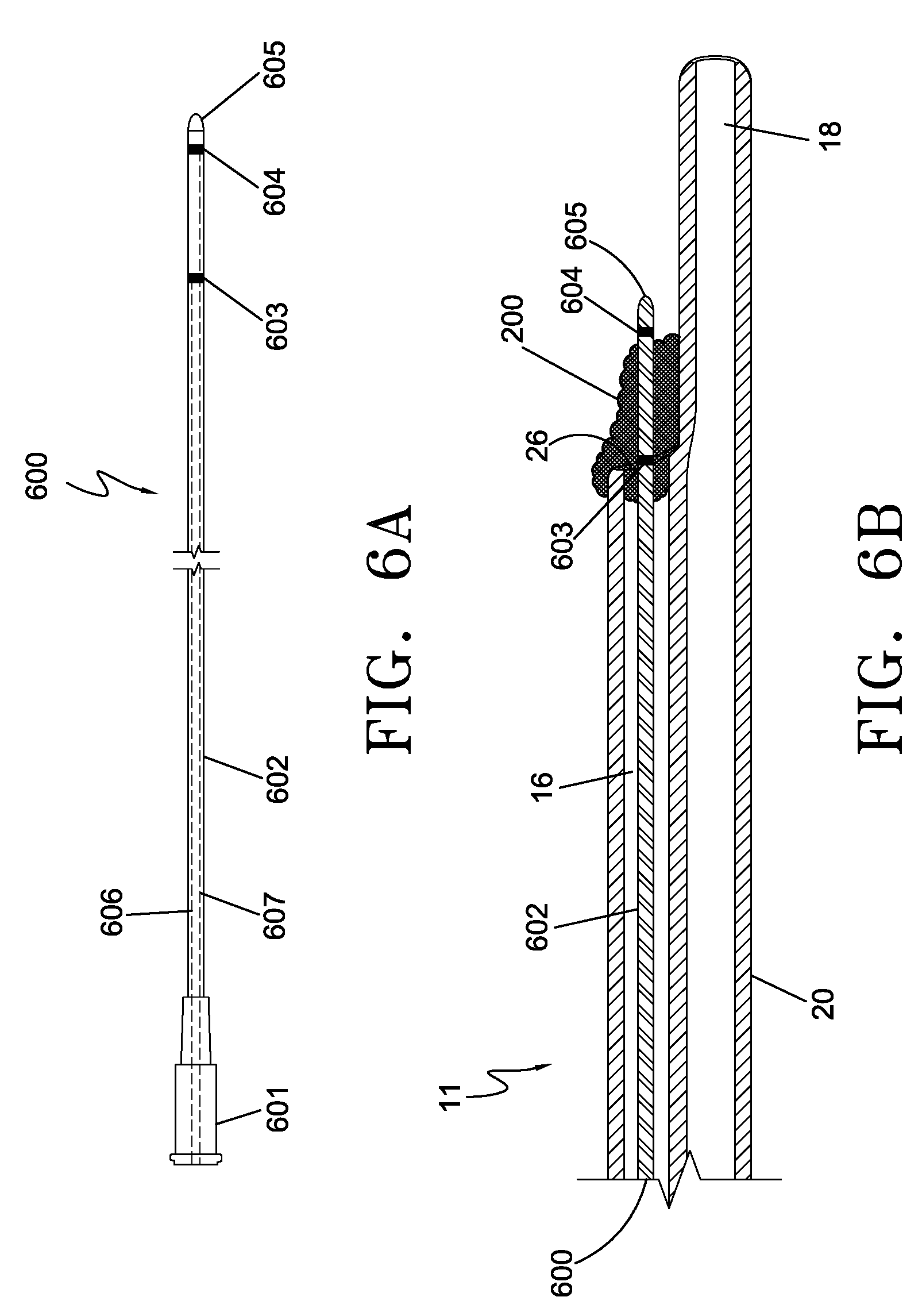
[0022] FIG. 6A is a plan view of an electroporation electrode probe representing another embodiment of the current invention.
[0023] FIG. 6B is a partial longitudinal cross-sectional view of the distal segment of a venous catheter with the electroporation electrode probe of FIG. 6A inserted through the catheter lumen and positioned within a fibrin sheath formation.
[0024] FIG. 7A is an enlarged longitudinal cross-sectional view of an electroporation electrode probe representing yet another embodiment of the current invention.
[0025] FIG. 7B is an enlarged longitudinal cross-sectional view of the electroporation electrode probe of FIG. 7A illustrated electrodes in a deployed position.
[0026] FIG. 7C is a partial longitudinal cross-sectional view of the distal segment of a venous catheter with the electroporation electrode probe of FIG. 7A inserted through the catheter lumen with deployed electrodes positioned around the distal segment of the catheter.
[0027] FIG. 8 is a distal end view of the venous catheter shown in FIG. 7C illustrating the electrical field pattern created when the deployed electrodes are energized.
[0028] FIG. 9 is a flowchart depicting the method steps for fibrin sheath destruction using the electroporation catheter of FIG. 1A.
[0029] FIG. 10 is a flowchart depicting the method steps for fibrin sheath removal using the electroporation electrode probe of FIG. 6A or 7A.
[0030] FIG. 11 is a treatment setup for a patient for synchronization of the delivery of electroporation pulses with a specific portion of the cardiac rhythm.
DETAILED DESCRIPTION OF THE INVENTION
[0031] Electroporation is defined as a phenomenon that makes cell membranes permeable by exposing them to certain electric pulses. As a function of the electrical parameters, electroporation pulses can have two different effects on the permeability of the cell membrane. The permeabilization of the cell membrane can be reversible or irreversible as a function of the electrical parameters used. Reversible electroporation is the process by which the cellular membranes are made temporarily permeable. The cell membrane will reseal a certain time after the pulses cease, and the cell will survive. Reversible electroporation is most commonly used for the introduction of therapeutic or genetic material into the cell. Irreversible electroporation, also creates pores in the cell membrane but these pores do not reseal, resulting in cell death.
[0032] Irreversible electroporation has recently been discovered as a viable alternative for the ablation of undesired tissue. See, in particular, PCT Application No. PCT/US04/43477, filed Dec. 21, 2004. An important advantage of irreversible electroporation, as described in the above reference application, is that the undesired tissue is destroyed without creating a thermal effect. When tissue is ablated with thermal effects, not only are the cells destroyed, but the connective structure (tissue scaffold) and the structure of blood vessels are also destroyed, and the proteins are denatured. This thermal mode of damage detrimentally affects the tissue, that is, it destroys the vasculature structure and bile ducts, and produces collateral damage.
[0033] Irreversible and reversible electroporation without thermal effect to ablate tissue offers many advantages. One advantage is that it does not result in thermal damage to target tissue or other tissue surrounding the target tissue. Another advantage is that it only ablates cells and does not damage blood vessels or other non-cellular or non-living materials such implanted medical devices (venous catheters for example).
[0034] Fibrin sheaths that form on venous catheters are primarily made up of smooth muscle cells with membranes. Therefore, destruction of the fibrin sheath by irreversible electroporation without causing any thermal effects is a viable method of treating fibrin growth. It is also possible to destroy the cellular structure of fibrin sheath formations using reversible electroporation combined with a drug. This process is known as electroporation-mediated chemotherapy and has been used to introduce chemotherapy drugs into a tumor at an intracellular level. What has not been previously described is the use of electroporation-mediated chemotherapy for the introduction of therapeutic agents, such as cytotoxic agents, into healthy but undesirable tissue such as the smooth muscle cells of a fibrin sheath formation. Cytotoxic agents are transported into the interior of the cell through the transient pore formations, ultimately causing cell death. In this manner, the underlying cellular structure of a fibrin sheath formation can be destroyed by the introduction of cytotoxic agents into the smooth muscles cells comprising the sheath.
[0035] Although the following example discusses using the present invention and method to destroy fibrin sheath growth, persons of ordinary skill in the art will appreciate that the present device and method can treat any undesirable cellular growth, including infectious cells.
[0036] FIG. 1A illustrates an indwelling electroporation venous catheter 10 with fibrin sheath destruction capabilities. The catheter 10 is comprised of a catheter shaft 25 that extends from a distal end opening 28 to a bifurcate hub 49 and two extension tubes 30, 32. The extension tubes 30, 32 terminate at hub connectors 34, 35 for connection to a dialysis machine. Clamps 41, 42 serve to close off the extension tubes 30, 32 between dialysis sessions. The catheter shaft 25 has at least a first withdrawal lumen 16 and a second supply lumen 18, which share a common internal septum 24, as illustrated in FIG. 1B. First lumen 16 and second lumen 18 extend longitudinally through substantially the entire length of the catheter shaft 25, terminating at distal openings 26 and 28, respectively. Side holes 31 and 33 provide supplemental access to lumens 16 and 18, respectively. FIG. 1B depicts a cross-sectional view of the catheter taken along lines A-A of FIG. 1A illustrating the Double-D lumen shape. Although the cross-sectional lumen configuration shown is a Double-D shape, it is contemplated that lumens 16 and 18 of catheter 10 may have any suitable cross-section lumen shape as required for the particular use of catheter 10.
[0037] Catheter 10 includes an electrical connector 500 extending proximally from hub 49 and in the illustrated embodiment positioned between the extension tubes 30 and 32. Catheter 10 also includes a plurality of electrodes 150 attached to the outer surface of the catheter shaft 25. The location of the electrodes on the catheter may be anywhere along the shaft, but the electrodes may generally be located near the distal section of the shaft where the fibrin sheath formation most severely compromises the fluid flow of the device. Furthermore, the size and shape of the electrodes can vary. For example, the electrodes can be ring-shaped, spiral-shaped, or can exist as segmented portions. The electrodes may also be a series of strips placed longitudinally along the catheter shaft surface. The electrodes may be comprised of any suitable electrically conductive material including but not limited to stainless steel, gold, silver and other metals.
[0038] A plurality of electrically conducting elements (e.g., electrical wires) 160, shown in FIG. 1B, extend longitudinally within the wall of the catheter shaft and function to connect each electrode 150 to a source of electrical energy in the form of a generator (not shown) by connection through the electrical connector 500. Each electrically conducting element 160 extends from an electrode 150 to which it is connected to terminate in electrical connector 500. An extension cable (not shown) is attached to electrical connector 500 to complete an electrical circuit between the electrodes 150 and the electrical generator through the electrically conducting elements 160. The electrically conducting elements 160 may be comprised of any suitable electrically conductive material including but not limited stainless steel, copper, gold, silver and other metals. The catheter shaft is comprised of a non-conductive material such as urethane, and functions as an electrical insulator insulting each electrically conducting element 160 from the other elements 160 and ensuring that the energy is directed to the exposed electrodes.
[0039] FIGS. 2A and 2B illustrate an indwelling electroporation venous catheter 10 of FIG. 1A implanted in the body of a patient 400. Catheter 10 is inserted into vein 404 of a patient 400 with the distal portion of the catheter 10 located at the junction of the superior vena cava 408 and the right atrium of the heart 412, where blood volume and flow rates are maximized. FIG. 2B illustrates fibrin sheath formation 200 attached to the outer wall 25 of the distal segment of catheter 10. As illustrated, the fibrous material occludes the distal end holes 26 and 28 and side holes 31 and 33, thus impairing the functionality of the catheter. Fibrin sheath formation 200 may originate anywhere along the catheter shaft 25 where platelet aggregation begins. For example, fibrin sheath growth 200 may originate at the distal end of the catheter and then develop into a matrix of smooth muscle cells which can block the distal openings 26, 28 and side holes 31 and 33 of the catheter 10.
[0040] The electrodes 150 are adapted to administer electrical pulses as necessary in order to reversibly or irreversibly electroporate the cell membranes of the smooth muscle cells comprising the fibrin sheath 200 located along the outer surface of catheter shaft 25 or inside of the catheter shaft 25 within a treatment zone. By varying parameters of voltage, number of electrical pulse and pulse duration, the electrical field will either produce irreversible or reversible electroporation of the cells within the fibrin sheath 200. The pulse generator of the present invention can be designed to deliver a range of different voltages, currents and duration of pulses as well as number of pulses. Typical ranges include but are not limited to a voltage level of between 100-3000 volts, a pulse duration of between 20-200 microseconds (more preferably 50-100 microseconds), and multiple sets of pulses (e.g. 2-5 sets) of about 2-25 pulses per set and between 10 and-500 total pulses. The pulse generator can administer a current in a range of from about 2,000 V/cm to about 6,000 V/cm. The pulse generator can provide pulses which are at a specific known duration and with a specific amount of current. For example, the pulse generator can be designed upon activation to provide 10 pulses for 100 microseconds each providing a current of 3,800 V/cm +/-50% +/-25%, +/-10%, +/-5%. The electroporation treatment zone is defined by mapping the electrical field that is created by the electrical pulses between two electrodes.
[0041] When electrical pulses are administered within the irreversible parameter ranges, permanent pore formation occurs in the cellular membrane, resulting in cell death of the smooth muscle cells of the fibrin sheath. In another aspect, by proactively administering the electrical pulses according to a predetermined schedule, fibrin sheath growth 200 on the catheter can be prevented altogether. Alternatively, electrical pulses may be administered within a reversible electroporation range. Cytotoxic drugs, such as a chemotherapy agent, may be administered through either catheter lumen into the volume of fibrin sheath during the electroporation treatment. Temporary pores will form in the cellular membranes of the smooth muscle cells comprising the fibrin sheath, allowing the transport of the drug into the intracellular structure, resulting in cell death.
[0042] FIG. 3A illustrates an enlarged partial plan view of the distal segment of the electroporation venous catheter 10 with fibrin sheath removal capabilities. A plurality of electrodes 150 are disposed on the outer surface of the distal portion of the catheter shaft 25. The electrodes 150 are shaped as rings coaxially surrounding the catheter shaft. In this embodiment, each electrode 150 is individually electrically coupled to an electrically conducting element 160. As an example, the distal most electrode 150A is connected to electrically conducting element 160A, which extends within the side wall of the catheter shaft 25 from electrical connector 500 (FIG. 1A) to electrode 150A. Electrically conducting element 160B extends from connector 500 and terminates at electrode 150B. Electrode 150C, as shown, circumferentially surrounds the outer walls of both lumens 16 and 18 and is electrically coupled to electrically conducting element 160C which terminates in the catheter side wall at the location of electrode 150C. Similarly, electrode 1500, 150E and 150F are electrically coupled to conducting elements 160D, 160E and 160F respectively.
[0043] FIG. 3B depicts an enlarged cross-sectional view of catheter 10 taken along lines B-B of FIG. 3A at the location of electrode 150D. Catheter shaft 25 is comprised of lumens 16 and 18 separated by a septum 24. Coaxially surrounding shaft 25 is ring electrode 150D. Electrically conducting elements 160A, 160B, 160C and 160D are also illustrated embedded within the catheter shaft 25 wall. The catheter shaft 25 is comprised of a non-conductive urethane material and functions as an electrical insulator insulting each electrically conducting element from the other elements and from those electrodes 150 not physically coupled to the conducting element. Electrically conducting element 160D is shown in FIG. 3B as being electrically coupled to electrode 150D by an electrically conductive material 320. To create the coupling, the catheter shaft 25 surface may be skived until the outer surface of the coupling wire 160D is exposed. This process creates skive pocket 310. Pocket 310 is filled with electrically conductive material 320 to create an electrically conductive pathway between electrode 150D and electrically conducting element 160D.
[0044] Other methods known in the art for electrically coupling the electrodes 150 and electrically conducting elements 160 are within the scope of this invention. Examples of coupling methods include spot welding the electrode 150 to the conducting element 160, soldering and mechanical crimping, among other techniques. Other electrically conducting element configurations are also within the scope of this invention. For manufacturing efficiencies, for example, shaft 25 may be extruded with all electrically conducting elements 160 embedded in the shaft for substantially the entire length of the catheter shaft 25. Only the electrode 150 to which the conducting element 160 is coupled will be activated when the electrical circuit is energized. Those segments of the electrically coupling elements 160 distal of the electrode 150 connection will not generate an electrical field of sufficient intensity to induce a clinical effect when activated since they are not connected to any other electrodes.
[0045] FIG. 4 depicts the electrical field pattern created when electrical pulses are applied to the catheter 10 shown in FIG. 3A. In the embodiment shown, electrical pulses may be simultaneously applied to all electrodes 150A-150F with alternating polarity. As an example, electrode 150F may have a positive polarity, electrode 150E a negative polarity, electrode 150D a positive polarity, electrode 150C a negative polarity, electrode 150B a positive polarity and electrode 150A a negative polarity. This arrangement creates the electrical field pattern illustrated by field gradient lines 210, 220 and 230. The voltage pulse generator (not shown) is configured to generate electrical pulses between electrodes in an amount which is sufficient to induce irreversible electroporation of fibrin sheath smooth muscle cells without creating a clinically significant thermal effect to the treatment site. Specifically, the electrical pulses will create permanent openings in the smooth muscles cells comprising the fibrin sheath, thereby invoking cell death without creating a clinically significant thermal effect. The smooth muscle cells will remain in situ and are subsequently removed by natural body processes.
[0046] The strongest (defined as volts/cm) electrical field is nearest to the electrodes 150 and is depicted by gradient line 210 in FIG. 4. As the distance away from the electrode 150 increases, the strength of the electrical field decreases. Gradient line 230 represents the outer perimeter of irreversible electroporation effect and as such defines the outer boundary of cell kill zone. As an example, any fibrin or other bio-film growth on the surface of the catheter within the outer perimeter 230 will undergo cell death by irreversible electroporation.
[0047] Because the voltage pulse generation pattern from the generator does not generate damaging thermal effect, and because the voltage pulses only ablate living cells, the treatment does not damage blood, blood vessels or other non-cellular or non-living materials such as the venous catheter itself.
[0048] By utilizing separate electrically conducting elements 160 for each electrode 150, different fibrin sheath growth 200 segments may be treated independently. For example, a computer (not shown) within the generator can control the firing of each electrode pair independently and according to a predetermined pattern. Alternatively, the creation of a series of electrical fields may be accomplished by sequentially firing pairs of electrodes within one treatment session to ensure that the entire length of the fibrin sheath is treated. Sequentially polarizing and applying electrical energy to a subset of the total number of electrodes as described herein may be used to target fibrin growth on a specific segment of the catheter shaft. As an example, FIG. 5 depicts the electrical fields created when electrical pulses are applied to two electrodes only. Electrode 150B may be set to have a positive polarity and electrode 150C a negative polarity. When electrical pulses are applied to these two electrodes, an electrical field pattern is created as illustrated by gradient lines 210, 220 and 230. Fibrin sheath build-up within the outer perimeter of gradient line 230 will be effectively destroyed.
[0049] In another aspect of the invention, the device and method can be used to cause the destruction of infectious cells, such as catheter-related bacteremia, that have grown around the indwelling catheter. These infectious cells can be located anywhere along the indwelling shaft. Research has also shown that infectious cells can form in combination with fibrin sheath growths, because fibrin sheath can enhance catheter-related bacteremia by providing an interface for adherence and colonization. These pathogens may then produce a "biofilm" which is impenetrable to systemic antibiotics leading to a cause of catheter dysfunction, subsequent removal, and the attendant increase in morbidity and mortality. Referring again to FIG. 4, the pulse parameters that characterize the field gradient line can be adjusted to vary the treatment zone according to the location of the fibrin sheath growth and/or infectious cells to be destroyed. Furthermore, in some embodiments of the invention, the electrodes can be positioned at any location necessary to destroy any such infectious cells that have grown around the indwelling catheter. For example, the electrodes can be positioned at a proximal section of the indwelling catheter for treating infectious cells, that have grown around the tunneled portion of the catheter. In addition, the electrodes can be positioned to destroy infectious cells that have grown near the insertion site of the indwelling catheter.
[0050] In another aspect of the invention, by periodically administering the electrical pulses according to a predetermined schedule, fibrin sheath growth on the catheter shaft 20 can be prevented altogether. As an example, the formation of a fibrin sheath may occur as early as 24 hours after catheter implantation. Smooth muscle cells develop within seven days. Application of electrical pulses applied to fibrin sheath at regular intervals post-implantation may be effective in preventing fibrin sheath growth during the catheter implantation period.
[0051] Referring now to FIG. 6A and 6B, FIG. 6A is a plan view of an electroporation probe 600 representing another embodiment of the current invention. In this embodiment an electroporation probe 600 is comprised of an electrical connector 601, a flexible shaft body 602 on which two electrodes 603 and 604 are positioned in a coaxial arrangement with the shaft, and a distal end or tip 605. The electrodes are preferably positioned near a distal section of the shaft. As previously described electrically conductive elements 606 and 607 extend longitudinally from the electrical connector 601 to the electrodes 603 and electrode 604 respectively. The electrically conductive elements 606 and 607 may be embedded within the wall of the shaft 602, as previously described, or alternatively may be insulated and positioned within a lumen of shaft 602.
[0052] FIG. 6B is a partial longitudinal cross-sectional view of the distal segment of a venous catheter 11 with the distal section of electrode probe 600 of FIG. 6A inserted through the catheter lumen 16 and positioned within a fibrin sheath formation 200. To destroy the fibrin sheath 200, the electrode probe 600 is inserted into the catheter lumen 16 and advanced through the distal end hole 26. Electrode probe distal tip 605 may be tapered to provide a non-traumatic leading edge capable of advancing through the sheath formation 200. Electrodes 603 and 604 are positioned within the fibrin sheath formation 200 such that when electrical pulses are applied, an electrical field (not shown) will be created that encompasses the fibrin sheath 200 in its entirety. After the electroporation process has destroyed the fibrin sheath, the probe is removed from the catheter. Alternatively, cytotoxic agents may be administered through lumen 16 and directed into the fibrin formation. Electroporation pulses may be applied to reversibly electroporate the smooth muscle cells of sheath 200, creating a pathway through the cell membrane for the agent to enter the cell.
[0053] The embodiment illustrated in FIGS. 6A and 6B is particularly advantageous when treating a fibrin sheath formation that has advanced into the lumen of the catheter and occludes the end holes and/or side holes of the catheter. Another advantage of the embodiment of FIG. 6A is that the probe is a separate device inserted into the patient through the implanted catheter only when treatment is required and then is removed immediately after treatment. The probe is not part of the implanted catheter device and is removed immediately after treatment. Utilizing a separate device to perform electroporation reduces the possibility of electrode or conducting wire damage due to long term implantation as well as simplifying the manufacturing of the device and costs associated with the manufacture.
[0054] FIGS. 7A-7C illustrate a third embodiment of the present invention wherein the electroporation probe 700 is comprised of deployable electrodes. As with the previous embodiment, the electroporation probe 700 is inserted into the lumen of a catheter prior to the application of electrical pulses, and is removed after treatment. Referring first to FIG. 7A, electrode probe 700 is comprised of an electrical connector hub 712, an outer sheath 701 extending from the hub 712 to a distal end hole 702, and a plurality of electrically conducting elements 709 and 704 arranged within the outer sheath 701 and within a lumen. Electrically conducting elements 709 and 704 are connected proximally to the electrical connector/hub 712 and extend distally within the outer sheath 701 for substantially the entire length of the sheath. Insulating sleeves 707 and 703 coaxially surround electrically conducting elements 709 and 704 from the hub 712 to insulation distal ends 721 and 723. Un-insulated portions 711 and 705 of electrically conducting elements 709 and 704 extend distally. Portions 711 and 705, being un-insulated, act as electrodes when the electrical circuit is energized.
[0055] Button 713 on hub 712 is used to deploy and retract the electrically conducting elements 709 and 704 relative to the outer sheath 701. The undeployed position of electroporation probe 700 is illustrated in FIG. 7A. As shown, the electrically conducting elements 709 and 704 are completely contained within the lumen of the outer sheath 701 including the un-insulated portions 711 and 705. The fully deployed position of the electrode probe 700 is illustrated in FIG. 7B. Button 713 is advanced distally to deploy the distal sections of electrically conducting element 709 and 704 out of the distal end hole 702 of outer sheath 701. When fully deployed, the distal section of the electrically conducting elements 709 and 704 extend outwardly from end hole 702, with a profile that curves outwardly and then extends proximally in a substantially parallel relationship with the longitudinal axis of the probe 700. The distal portion of insulating sleeves 707 and 703 form at least part of the curve terminating at points 721 and 723. The un-insulated portions 711 and 705 form the active electrodes and extend from insulation end points 721 and 723 in a proximal direction adjacent (such as parallel to) the outer wall of outer sheath 701.
[0056] Electrically conductive elements 704 and 709 may be formed of any suitable electrically conductive material including but not limited stainless steel, gold, silver and other metals including shape-memory materials such as nitinol. Nitinol is an alloy with super-elastic characteristics which enables it to return to a pre-determined expanded shape upon release from a constrained position. The outer sheath 701 constrains the distal segments of the undeployed electrically conductive elements 704 and 709 in a substantially straight distal configuration. Once the electrodes are deployed from the distal end of the outer sheath 701 as previously described, the distal sections of electrically conductive elements 704 and 709 form the "J-hook" curved profile shown in FIG. 7B.
[0057] FIG. 7C illustrates a partial longitudinal cross-sectional view of a catheter 11 with the electrode probe 700 in a deployed position. In use, the undeployed electrode probe 700 is inserted into lumen 18 of catheter 11 and advanced to the distal end hole 28. Once correctly positioned, button 713 (shown in FIG. 7B) is advanced in the direction shown by the hub arrow to deploy the distal sections of electrically conducting elements 709 and 704 outside of the outer sheath 701 and the catheter distal end hole 28. When fully deployed, the exposed segments 711 and 705 of electrically conducting elements 709 and 704 extend in a proximal direction adjacent to and parallel to the outer wall of catheter shaft 25.
[0058] FIG. 8 is an enlarged end view of the catheter of FIG. 7C depicting the electrical fields created when electrical pulses are applied to electrode probe 700. Application of pulses creates an electrical field pattern between the un-insulated portions 711 and 705 (shown in FIG. 7C) of the electrically conducting elements. This arrangement creates the electrical field pattern illustrated by field gradient lines 210, 220 and 230. The strongest (defined as volts/cm) electrical field is nearest to the active electrodes and is depicted by gradient line 210. As the distance away from the electrodes increase, the strength of the electrical field decreases. Gradient line 230 represents the outer perimeter of irreversible electroporation effect and as such defines the outer boundary of cell kill zone. As an example, any fibrin or other bio-film growth on the surface of the catheter within the outer perimeter 230 will undergo cell death by irreversible electroporation.
[0059] If fibrin sheath has formed around end hole 26, electrode probe 700 may be inserted into lumen 16 (shown in FIG. 7C), positioned and then electrodes deployed as previously described. Application of electrical pulses will create an electrical field as shown in FIG. 8, except the field will be centered around end hole 26 rather than end hole 28. It is also within the scope of this invention to utilize two electrode probes of opposite polarity with one probe placed in each lumen. In this embodiment, the electrical field may be created between the two probes, creating an electrical field similar to that illustrated in FIG. 4.
[0060] The deploying electrode probe 700 illustrated in FIGS. 7A-C and 8 is particularly advantageous in destroying fibrin build-up along the outer surface of the distal segment of an implanted catheter. Probe 700 may be used to clear fibrin sheath formations from each lumen of a catheter as well as to irreversibly electroporate fibrin sheath occluding side holes located near the distal end of the catheter. The number of electrically conducting elements 704 and 709 may be varied to accommodate various size catheters and fibrin sheath volumes. In addition, the length of the exposed segment 711 and 705 may be adjusted based on the catheter length and/or the length of the fibrin formation extending proximally from the distal end holes of the catheter. It is also within the scope of this invention to configure a probe with two deployable electrodes which, when deployed, are arranged at an angle relative to each other of less than 180 degrees (i.e., not parallel to each other). After applying electrical pulses to create an electrical field pattern, the probe may be rotated and pulse applied again to create a second electrical field pattern. This process is repeated until the entire 360 degree circumference of the outer surface of the catheter has been treated. It is also understood that any of the embodiments illustrated may be used to reversibly electroporate the fibrin sheath for the purpose of introducing therapeutic agents into the smooth muscle cells.
[0061] FIG. 9 illustrates the procedural steps associated with performing irreversible or reversible electroporation treatment using the device which is depicted in FIGS. 1-5. After the fibrin sheath formation has been detected and the location of the formation determined using ultrasound or fluoroscopic imaging, electrical connector 500 is connected to an electrical generator (801) using an extension cable. This completes an electrical circuit between the electrodes 150 and the generator via the electrically conducting elements 160. Electrical pulses are applied across the electrodes in the desired pattern to electroporate the smooth muscle cells of the fibrin sheath (802). If the electrical generator treatment parameters are set to deliver electrical pulses within the reversible range (803), therapeutic agents may be injected through the catheter lumens (804) and pass into the fibrin sheath formation through either the side holes or end holes of the catheter. After treatment, the extension cable is disconnected from the electrical connector (805). Non-thermal death of the smooth muscle cells will occur within the first twenty-four hours after electroporation treatment followed by a cellular breakdown of the fibrin sheath.
[0062] Referring now to FIG. 10, the method of performing electroporation treatment using the device depicting in FIGS. 6A-B or FIG. 7A-C is illustrated. After the fibrin sheath formation has been detected and the location of the formation determined using ultrasound or fluoroscopic imaging, electrode probe 600 (FIGS. 6A-B) or 700 (FIGS. 7A-C) is inserted into the venous catheter (901). The probe is then positioned relative to the fibrin sheath location as previously described. The electrical connector 601 or 712 is then connected to an electrical generator using an extension cable (902). If using electrode probe 700, the electrodes are deployed (904) and positioned outside of the catheter shaft as shown in FIG. 7C. Electrical pulses are then applied across the electrodes (905) creating a field gradient sufficient to non-thermally electroporate the smooth muscle cells present in the fibrin sheath. If the electrical generator treatment parameters are set to deliver electrical pulses within the reversible range (906), therapeutic agents may be injected through the catheter lumen (907) passing into the fibrin sheath formation through either the side holes or end holes of the catheter. Alternatively, the electroporation probe may be configured to include a lumen through which agents may be administered. If using probe 700, the electrodes are then retracted (908) within the outer sheath 701. After the procedure is complete, the probe is removed from the catheter (909). Non-thermal death of the smooth muscle cells occur after electroporation treatment followed by a cellular breakdown of the fibrin sheath.
[0063] In one embodiment, the electroporation pulses can be synchronously matched to specifically repeatable phases of the cardiac cycle to protect cardiac cellular functioning. See, for example, U.S. patent application Ser. No. 61/181,727, filed May 28, 2009, entitled "Algorithm For Synchronizing Energy Delivery To The Cardiac Rhythm", which is fully incorporated by reference herein. This feature is especially useful when the electroporation pulses are delivered in a location that is near the heart. FIG. 11 illustrates a treatment setup for a patient for synchronization of the delivery of electroporation pulses with a specific portion of the cardiac rhythm. Electrocardiogram (ECG) leads 17, 19, 21 are adapted to be attached to the patient for receiving electrical signals which are generated by the patient's cardiac cycle. The ECG leads transmit the ECG electrical signals to an electrocardiogram unit 23. The electrocardiogram unit 23 can transmit this information to a synchronization device 25 which can include hardware or software to interpret ECG data. If the synchronization device 25 determines that it is safe to deliver electroporation pulses, it sends a control signal to a pulse generator 27. The pulse generator 27 is adapted to connect to electrical connector 500 for delivering electroporation pulses. Each of the synchronization device 25 and pulse generator 27 can be implemented in a computer so that they can be programmed.
[0064] The present invention affords several advantages. Fibrin sheath growths are destroyed without having to remove the catheter from the patient. The treatment is minimally-invasive and highly efficacious. Because irreversible electroporation does not create thermal activity, the catheter is not damaged by the treatment. Fibrin sheath growths are treated quickly, and the catheters can be maintained according to a predetermined schedule to insure that the distal openings remain clear.
[0065] Although the irreversible electroporation device and method has been described herein for use with dual-lumen catheters, it should be understood that the irreversible electroporation device can be used with single lumen catheters or multiple-lumen catheters. Another type of venous catheter which is prone to fibrin sheath formation is a venous catheter that is connected to an implanted port. An example of a venous catheter attached to an implanted port is disclosed in U.S. Pat. Application Publication No. 2007/0078391, which is incorporated herein by reference. Electrode probe devices described in FIGS. 6A-B and 7A-C may be used to remove fibrin sheath from catheter shafts connected to implanted port devices. In the case of port devices, the probe may be inserted through a needle lumen that has been inserted into the septum. The probe device may include a guidewire lumen to assist in tracking through the stem channel and into the catheter shaft lumen. Fibrin sheath formations on PICC lines or other central venous catheters may also be destroyed using the devices and methods illustrated herein.
[0066] While the embodiments shown use pulses that cause IRE, persons of ordinary skill in the art will appreciate that other types of pulses can be used for the destruction of the fibrin sheath growths. In particular, ultrashort sub-microsecond pulses (pulses of less than 1 microsecond in duration) can be used to induce apoptosis that cause damage to the intracellular structures such as a cell nucleus.
[0067] The above disclosure is intended to be illustrative and not exhaustive. This description will suggest many modifications, variations, and alternatives may be made by ordinary skill in this art without departing from the scope of the invention. Those familiar with the art may recognize other equivalents to the specific embodiments described herein. Accordingly, the scope of the invention is not limited to the foregoing specification.
* * * * *
D00000
D00001
D00002
D00003
D00004
D00005
D00006
D00007
D00008
D00009
D00010
D00011
D00012

XML
uspto.report is an independent third-party trademark research tool that is not affiliated, endorsed, or sponsored by the United States Patent and Trademark Office (USPTO) or any other governmental organization. The information provided by uspto.report is based on publicly available data at the time of writing and is intended for informational purposes only.
While we strive to provide accurate and up-to-date information, we do not guarantee the accuracy, completeness, reliability, or suitability of the information displayed on this site. The use of this site is at your own risk. Any reliance you place on such information is therefore strictly at your own risk.
All official trademark data, including owner information, should be verified by visiting the official USPTO website at www.uspto.gov. This site is not intended to replace professional legal advice and should not be used as a substitute for consulting with a legal professional who is knowledgeable about trademark law.