Modular Forearm Brace Mounting System(s) For Handguns
Burkhart, III; Frederick Edward ; et al.
U.S. patent application number 16/217545 was filed with the patent office on 2019-08-22 for modular forearm brace mounting system(s) for handguns. The applicant listed for this patent is Frederick Edward Burkhart, III, James Eric Caruthers. Invention is credited to Frederick Edward Burkhart, III, James Eric Caruthers.
| Application Number | 20190257613 16/217545 |
| Document ID | / |
| Family ID | 67617658 |
| Filed Date | 2019-08-22 |


View All Diagrams
| United States Patent Application | 20190257613 |
| Kind Code | A1 |
| Burkhart, III; Frederick Edward ; et al. | August 22, 2019 |
MODULAR FOREARM BRACE MOUNTING SYSTEM(S) FOR HANDGUNS
Abstract
An arm brace for a pistol is provided having removable grip panels. The arm brace with removable grip panels comprises a grip portion defining apertures for connecting to a pistol frame as a replacement grip. The arm brace further comprises a frame extending rearward from a lower end of the grip portion. Further, a concave wrist support element connected to the frame and configured to receive a user's wrist while the user's hand associated with the wrist is gripping the pistol.
| Inventors: | Burkhart, III; Frederick Edward; (Newport News, VA) ; Caruthers; James Eric; (Louisville, OH) | ||||||||||
| Applicant: |
|
||||||||||
|---|---|---|---|---|---|---|---|---|---|---|---|
| Family ID: | 67617658 | ||||||||||
| Appl. No.: | 16/217545 | ||||||||||
| Filed: | December 12, 2018 |
Related U.S. Patent Documents
| Application Number | Filing Date | Patent Number | ||
|---|---|---|---|---|
| 62708558 | Dec 13, 2017 | |||
| 62712397 | Jul 31, 2018 | |||
| Current U.S. Class: | 1/1 |
| Current CPC Class: | F41C 23/12 20130101 |
| International Class: | F41C 23/12 20060101 F41C023/12 |
Claims
1. An arm brace for a pistol having removable grip panels comprising: a grip portion defining apertures for connecting to a pistol frame as a replacement grip; a frame extending rearward from a lower end of the grip portion; a concave wrist support element connected to the frame and configured to receive a user's wrist while the user's hand associated with the wrist is gripping the pistol.
Description
CROSS-REFERENCE TO RELATED APPLICATIONS
[0001] This application claims the benefit of U.S. Provisional Patent Application No. 62/708,558 filed on Dec. 13, 2017, entitled "Brace for handgun support", and also claims the benefit of U.S. Provisional Patent Application No. 62/712,397 filed on Jul. 31, 2018, entitled "Modular Forearm Brace Mounting System(s) for Handguns", which are hereby incorporated by reference in its entirety for all that is taught and disclosed therein.
FIELD OF THE INVENTION
[0002] The present invention relates to a Modular Forearm Brace Mounting System for Handguns.
BACKGROUND OF THE INVENTION
[0003] Forearm and or Upper Arm Brace are similar in concept to those marketed & utilized for AR-15's, AK-47's, and other similar large frame rifles redesigned to meet the requirements of a handgun.
[0004] They are designed to be nearly universal or custom fit for different gun designs or manufacturer's grip angles, double or single column, revolver, single shot or semi-automatic, etc.
[0005] The device is utilized to provide more accurate shot placement and allow persons that are weaker, disabled, or utilizing heavier handguns to assist in supporting the weight, redistributing recoil forces, and shooting more accurately.
[0006] In this document the terms "Pistol" and "Handgun" will be used interchangeably and both are intended to refer to either Revolvers, Single Shots, or Semi-Automatics.
[0007] This entire System of Sub-Systems was developed to aid disabled users and users with diminished abilities to be able to, or to continue to be able to, fire a handgun. The design intent of the Brace Mounting System is to facilitate one handed firing of both normal and large frame handguns (for example a 1911 or a Glock for a "Normal" handgun and a Desert Eagle or a Ruger Blackhawk Hunter for a "Large Handgun"). The Brace Mounting System is intended to assist: those with limited or reduced mobility and strength, those just starting in the pursuit of the shooting sports that are not yet conditioned to the weight and recoil of handguns, and those wishing to reduce recoil and/or increase the accuracy potential of their shooting. Mounting the Forearm Brace of the Brace Mounting System onto the user's forearm distributes the weight of the weapon evenly and provides additional support to the user, all the while being operated and held with a single hand. Further the system assists by re-distributing the recoil produced by firing a handgun, and creates more surface area for contact reducing movement.
[0008] Very simply put, this device was developed to attach a brace to a handgun and to fit the brace onto the user's forearm. It is designed to fit normal to large sized handguns. Our system can utilize both existing braces currently sold by others and braces that we have designed ourselves. We have developed the means/mechanisms to attach these braces to handguns such as 1911s, Glocks, Large and small frame revolvers, Sig Model 320's, Barretta 92's, etc., etc. We also have developed a "universal model" designed to fit most any semiautomatic handgun from a single stack .22 to a double stack .45 apc.
[0009] Less than a month after placing the provisional patent the inventor had a mishap, he slipped in the shower and put his wrist/hand thru the glass shower door (the old-fashioned glass that shatters). He suffered multiple cut/damaged tendons and cut a nerve. He continues to suffer the effects of the injury and due to the lingering effects, cannot tolerate the recoil associated with firing handguns.
[0010] In the June 2018 Issue of the American Rifleman Mark A. Keefe I V (Editor in Chief) wrote "there is another group that is growing every day, and that is the aging armed citizen. NRA's Dr. Joe Logar, national manager of the Adaptive Shooting Program, gave a jam-packed presentation at the NRA Carry Guard Expo last year on that very subject, and I think he is really onto something. A large percentage of our population--an estimated 21 million Americans--suffers from arthritis, and that means they sometimes are no longer able to do things with their hands that previously would have been a cinch. Too, there are other users looking for a pistol solution, as described by NRA's Adaptive Shooting Program: "According to the most current census data, there are approximately 74 million individuals that identify as disabled. This population is growing as the Baby Boomer generation ages and as injured soldiers return from overseas."
[0011] The limitations of the prior art are addressed by providing an arm brace for a pistol having removable grip panels. The arm brace with removable grip panels comprises a grip portion defining apertures for connecting to a pistol frame as a replacement grip. The arm brace further comprises a frame extending rearward from a lower end of the grip portion. Further, a concave wrist support element connected to the frame and configured to receive a user's wrist while the user's hand associated with the wrist is gripping the pistol.
BRIEF DESCRIPTION OF THE DRAWINGS
[0012] FIGS. 1-45 show various views of a preferred embodiment of the invention.
DETAILED DESCRIPTION OF A PREFERRED EMBODIMENT
[0013] FIG. 1 shows a Buntline Special Version for mounting to Revolvers, via replaceable grips, tightening mechanisms, or other means, swinging & locking cam mechanisms, etc. One or both to attach to brace.
[0014] Specific Grips, Connection point to brace can be adhered by any means.
[0015] FIG. 2 is universal. It is adjustable for Grip Width.
[0016] Single or Multiple Retaining buttons, screws, pins, rivets, etc.
[0017] Adhered by any means including but not limited to welds, fusion, press fit, cast, mold, forge, rivets, bolt, etc. Also displayed is a Double wall option.
[0018] With any combo of bends and twists in any configuration.
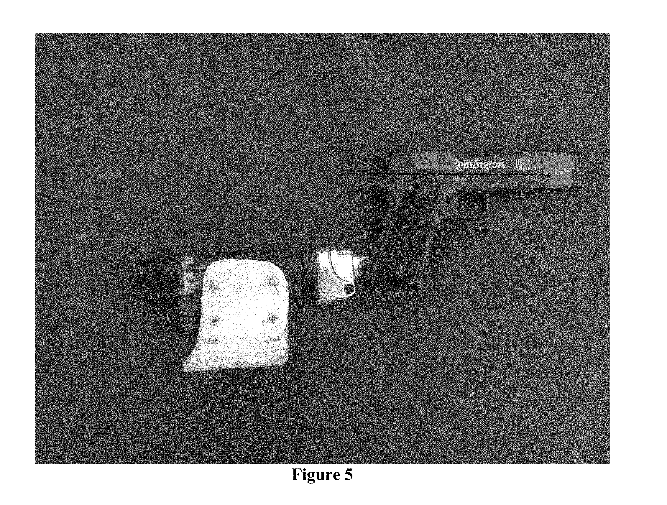
[0019] FIGS. 3-5 show exploded and Complete Views.
[0020] FIG. 3 is an Exploded view showing all components. Starting at top left of the photo and moving to the right: Handgun with Grip Connection Point (in this photo a Grip Panel/Rod Type (referred to as the Grip/Rod)) attached. Aluminum handgun Grip welded to a solid Aluminum Rod with a 3/4'' Outside Diameter (O.D.).
[0021] Note 1: Rod to Grip interface can occur both along the rear edge of the Grip panel, or the rod can overlap on the side of the Grip panel itself (to gain more contact area for a more secure connection).
[0022] Note 2: Version shown is for Right handed users (utilizing the Grip Panel on the left-hand side of the handgun). Versions for left handed users will utilize the Grip Panel on the right-hand side of the handgun.
[0023] Note 3: Holes drilled in the Rod may or may not be included.
[0024] Remnant of an AR-15 Upper Receiver with Takedown Pin hole remaining, customized.
[0025] Buffer Tube Liner (referred to as the "Tube")--Aluminum Tube roughly 1'' O.D. and 3/4''
[0026] Inside Diameter (I.D.). Roughly 4'' in length.
[0027] Tube to be inserted into the AR-15 Upper (where the bolt assembly would normally go).
[0028] Tube and AR-15 Upper Remnant to be welded together.
[0029] Insert Rod from Grip/Rod attachment into the Tube and weld the Tube and the Rod together.
[0030] For production purposes, one or more of these components may be formed as a single piece or as sets of pieces: Grip, Rod, AR15 Upper Remnant, Tube.
[0031] Starting bottom left of the photo and going clockwise:
[0032] Remnant of an AR-15 Lower Receiver with Takedown Pin hole remaining, customized. May or may not include internal components of the Takedown pin such as (detent pin, springs, and hex nut). These components ensure only partial removal, and thus retention, of the takedown pin when it is pulled out to change handguns or for storage.
[0033] AR-15 Takedown Pin. For insertion between the AR Upper and Lower, exactly as in use with an AR-15 utilizing spring, detent and screw for retention. To utilize any Takedown Pins for AR-15's.
[0034] AR15 Rear Receiver Plate (Anti-Rotational plate). May utilize any AR-15 Rear Receiver Plate.
[0035] AR-15 Castle Nut. May utilize any AR-15 Castle Nut.
[0036] AR-15 Buffer Tube. Tube may be modified for length overall and length of "channel" for position adjustment. Width of channel may be modified. Channel may have fewer or more "settings for length" then the current 6 positions. Buffer Tube shown in photos has been modified for overall length, and length of the "channel." May utilize either round "pistol type buffer tubes or carbine or rifle shaped buffer tubes.
[0037] Option for storage in "Tube" between Brace and grips. "Tube" also referred to as connection with or without removable plugs, caps or other closure type devices. Solid or mobile internal bulkheads to retain stored material(s). This can also be seen in FIGS. 34 to 44.
[0038] Brace Chassis and/or "Tube" with compatibility to mount Picatinny or alternate mounting systems and hardware for the addition of gun accessories.
[0039] Brace Chassis. The Brace Chassis was an AR-15 M-4 Stock, but it has been highly modified and customized, including but not limited to shortening for length from the front and the rear. Reduction of the rear component (formerly the butt-plate). The rear component has been maintained to ensure structural integrity of the chassis and retention of Straps (when included and utilized Strap or Straps are intended to be optional. Location of strap(s) may change. Strap holes may be utilized for sling locations. External sling or strap locations may be added). Holes drilled and tapped on both the right-hand and left-hand sides, as well as the top of the Brace Chassis for Brace Mounting Screws. Location of these holes may change. These holes may utilize inserts for structural integrity. Holes may be sized to utilize Brace at one location and Picatinny or other type mounting system on other location(s). Brace Chassis may or may not have cuts or outer retention devices for the use of a strap or straps.
[0040] Brace Screws (2) (exact hardware may not be screws) for securing the Brace to the Brace Chassis.
[0041] Cup Shaped Brace with holes drilled for screws (referred to as Cup Brace or Brace). polymer to come with a standard shape, but may be user adjustable to allow the brace to custom fit each individual for size, diameter, shape, etc. The Brace has 3 sets of screw holes (greater or fewer holes and locations may change). Allowing up to 5 different positions for mounting on the right-hand side of the brace chassis, and 5 positions for mounting on the left-hand side of the brace chassis (detailed description of positions below). Brace may or may not have cuts, slits or other indentations or penetrations for the installation and/or retention of a strap or straps.
[0042] On left-hand side of the Brace Chassis with the Brace cupped away from the chassis:
[0043] Screws in top holes (brace severely below and left of the Chassis).
[0044] Screws in middle holes (brace slightly below and left of the Chassis).
[0045] Screws in center holes (brace centered on the Chassis).
[0046] Flip brace over (still cupped away from the chassis).
[0047] Screws in center holes (brace centered on the Chassis). This is a mirror image of the previous position.
[0048] Screws in middle holes (brace slightly above and left of the Chassis).
[0049] Screws in top holes (these would appear as bottom holes due to relation to the Brace Chassis (brace severely above and left of the Chassis).
[0050] Brace installed on top of Brace chassis utilizing any holes in the Brace for screw locations.
[0051] Options for Brace Cupping toward the Brace Chassis are retained in the design basis.
[0052] Braces can be mounted in any position along/around the Brace Chassis.
[0053] Note 1: all components can be constructed of alternative materials including, but not limited to Aluminum, Steel, Alloys, Polymers, Wood, Composites, Layered materials such as Micarta and G10, Rubbers, Leather, Fiberglass, etc.
[0054] Note 2: May include means for mounting accessories such as Picatinny Rails, M-LOC, Keymod, or others.
[0055] Note 3: Entire system may be utilized as a platform for NFA devices--for example the Buffer Tube and Brace Chassis can be replaced with standard or modified Buffer Tubes and/or Stocks and may or may not utilize Brace and/or straps.
[0056] Note 4: Means for the Buffer Tube or Brace Chassis or Brace to be used for storage is retained (for example, but not limited to: remove the rear of the buffer tube, insert items, and reapply rear of the buffer tube).
[0057] Note 5: The system is designed and intended for use with or without additional brace mechanism installed on the Brace Chassis. The Brace Chassis is also designed and intended for use as a Stabilizing Brace without additional Brace components. The Bare Buffer Tube is designed and intended to be utilized as a Brace by itself. Any combo of Brace, Brace Chassis, Bare Buffer Tube and straps is envisioned.
[0058] FIG. 4 is a fully Assembled Right-hand View, Fully Extended with Cup Brace Installed for Right Handed Users. Shown fully assembled with Brace Chassis in the fully extended position, and with the Brace mounted on the right-hand side (for Right handed users) and in the most extended position.
[0059] FIG. 5 is a fully Assembled Right-hand View, Collapsed, with Cup Brace installed for Right Handed Users
[0060] Shown fully assembled with Brace Chassis in the collapsed position, and with the Brace mounted on the right-hand side (for Right handed users) and in the bottommost or most collapsed position.
[0061] FIG. 6 is a Left-hand View broken into the Main Sub-Assemblies (Front Sub Assembly and Rear Sub Assembly). Shows the Modular System in its 2 major Sub-Assemblies (Front and Rear) separated.
[0062] Note 1: The Takedown Pin is shown, but it is not in its normally installed position (in the AR-Lower). Brace is installed in on the Left-hand side (for Left handed users) and in the Centermost of 5 positions.
[0063] Note 2: For left handed users the opposite Grip Panel would be utilized (Grip Panel on the Right-hand side of the gun).
[0064] The concept of operation is that the Sub-Assemblies can be separated, and a different Front Sub Assembly for another pistol of the same or a different type (for example, but not limited to, a Beretta M-9/92, or a SIG 320, or a Glock) installed into the Rear Sub-Assembly. Or a different Rear Sub-Assembly can be installed on the same or different Front Sub-Assembly.
[0065] Note 3: The different types of pistols will utilize different mounting systems. All mounting systems may or may not include straps or other mechanisms to further secure the handgun to the various Grip Connection Points (see more in other Figures).
[0066] Note 4: Upon mating the AR Upper and Lower Remnants together the Tube will be inserted into the ID of the Buffer Tube. This will prevent rotation around the Takedown Pin and add rigidity to the system.
[0067] Note 5: Future versions may incorporate the means and methods to temporarily adjust the Buffer Tube Liner to allow folding of the device, and unfolding with the Buffer Tube Liner "locking" back into its normal position (manually or automatically).
[0068] Note 6: All dimensions and layout may vary to reduce length, increase ergonomics, or for other reasons including custom diameters or lengths that are proprietary
[0069] FIGS. 7-11 are depicted with a 5'9'' male user (the inventor). Brace Chassis is extended one position short of the maximum extension.
[0070] FIG. 7 is a Lower Right-hand User's View (5'9'' male), sight purposely not aligned.
[0071] FIG. 8 is a second person View of User (5' 9'' male) from the Right.
[0072] Note Inventor's scar from injury (starting from wrist bone and running toward the elbow (approximately 3 inches). Note 2: One strap is currently installed. Provisions have been made for 2 straps. One of 2 straps (more straps and no straps at all) are part of the design basis. Quantity of straps and location may change. Size of straps may change as well as orientation of straps and construction.
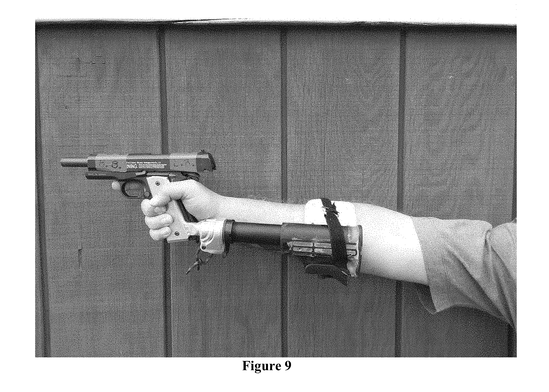
[0073] FIG. 9 is a Second Person View of User (5' 9'' male) from the Left.
[0074] FIG. 10 is a Second Person View of the User (5' 9'' male) from Above.
[0075] FIG. 11 is a Second Person View of the User (5' 9'' male) from Below.
[0076] Note Inventor's scars from injury--starts from center of wrist and runs outwards and down.
[0077] Note use of an extended Takedown Pin, devices to assist pulling pin (not limited to rope/string, metal shapes, custom "Dog Tags", etc.), and a different AR15 Rear Receiver Plate (Anti-Rotational plate).
[0078] Strings, ropes, takedown pin accessories of any kind included. Utilization of Rear Receiver Plate for other purposes also reserved.
[0079] FIG. 12 shows Brace Chassis Lower/Rear View, with Optional Cup Brace Installed and with Optional Strap(s) installed. Note this specific Strap is depicted only for clarity. Note second penetration (to the left of the current strap and to the left of the swell for the detent pin of the brace Chassis) for an additional optional strap.
[0080] Note 1: Straps may or may not have attachments (for example a ring of metal similar to a key chain ring (materials shape and size may vary) to aid users to grab the strap to ease manipulation of the straps. Means for tightening and retaining the position of the strap(s) may vary. The use of the straps to hold or retain devices when in use or not in use are retained. May include fittings to allow the straps to be tightened one-handed (one piece of hardware would be a ring to allow the strap to go thru the ring then to double back on itself for tightening purposes and then secured in place).
[0081] Note 2: The Buffer tube may be replaced with a Pistol type buffer to support the acceptance of different buffer tube style braces. Pistol type Buffer Tubes can be seen depicted in several of the Figures in this document, either currently made or made in the future.
[0082] Note 3: All braces intended and designed to be utilized with or without straps to further secure to the user's forearm.
[0083] Note 4: All Braces may either mount on a buffer tube (Buffer Tube with or without a channel (either an internal channel or an external channel), or indentations or built up areas), or directly to a Tube.
[0084] Note 5: The Brace Chassis without an additional Brace attached to it is also intended to be a Brace with or without straps.
[0085] Note 6: The Buffer Tube without an additional Brace Chassis and/or Brace attached to it is also intended to be a Brace with or without straps.
[0086] Note 7: Round Buffer tubes may have flats or indentations or built up areas cut into them for the L, Tee, and Pulling Elbow braces (not limited to these braces) to more securely mount the set screw or other device for mounting onto the round pistol buffers (flat surfaces for the set screws to snug against--rather than a flat bottom set screw setting against a round surface).
[0087] Note 8: All can be utilized in any configuration around the buffer tube (aligned anywhere around the clock from the 12 O'clock position completely 360 degrees back to the 12 o'clock.
[0088] Note 9: Photo depicts Brace Chassis with JB weld utilized to fill all "channels" and to attach the rear portion of the Brace Chassis to its main body. This will be all part of a final molded or cast product (with or without the use of JB weld). All Channels may or may not be filled. JB Weld is also utilized for more thread surface for the Brace Screws. Surface(s) for attachment of Braces may extend beyond the current body of the Brace Chassis. Additional screws, other fittings, and location of screws or other fittings may be changed.
[0089] Note 10: Some models have slots cut in the body of the Brace Chassis immediately below the Swell for the Buffer Tube area and immediately in front of, behind (or both) the swelled area for the Pin that locks the Brace Chassis into position on the Buffer Tube indentations for position adjustment. The location and quantity of these mounting locations for Straps, slings, or supporting mechanisms may change. May utilize different length, width, weight and types of straps and mounting and removing hardware. Width is currently limited by the space available fore and aft of the Pin area of the Brace Chassis.
[0090] Brace is molded to fit the "average forearm." It has three sets of 2 holes. Future models may have fewer holes, more holes, or be completely absent of holes. Holes are reinforced with metallic fittings. Metallic fittings may be replaced with built up portions of the brace itself or fittings constructed of other materials. Brace may be constructed of other Thermoplastics, polymers, metals, or other materials. Brace may or may not include slots, metal or polymer fittings, or external portions of the molding to support the addition of straps to further secure the Cup Brace to the user's forearm. The assembly may or may not utilize the brace. Dimensions are not fixed and length, width or thickness may vary. The brace may utilize spacers or fittings between the Brace and The Brace Chassis. The Brae may include a rear portion or a front portion. Portion of brace may be utilized for mounting of accessories. The Brace may mount around a Pistol type Buffer Tube via a sleeve or other mechanism.
[0091] Note 11: May incorporate a removable and washable (laundry or hand washable) "sleeve" or "sock" to aid user comfort and to allow distance between sensitive parts of the user's skin and the Brace. Currently envisioned as a fleece material with "ears" or "pockets" on both end that will go over the top and bottom surfaces of the brace and be connected between the 2 ears with a solid piece of material (between the brace and the user--may incorporate elastic to help retain on the brace. May incorporate a separate or additional piece of material for keeping the straps from coming into direct contact with the user's forearm. Colors and construction may vary as well as the types of material utilized.
[0092] FIG. 13 shows a Right-Rear View Pulling Elbow "L"-Shaped Brace with Storage Space with L Turned Down. Shown as an entire Rear Assembly with Buffer Tube (round pistol type), Castle Nut, Rear Receiver Plate, AR Lower Remnant and Take Down Pin.
[0093] Highly modified Electrical Conduit Pulling Elbow. The other conduit connection point has been removed and the resulting hole filled in. Removable cover allows a storage location for items (other connection may be kept in the future and plugged or left open). Removable cover may be located either on the rear, side(s), top, bottom, front, or Buffer Tube mounting area. May utilize other fittings or devices for tool-free removal of cover, or a shaped cap that can be secured and removed without tools. Brace, cover, and fittings can be constructed of metals, polymer, rubbers or other materials. Brace may be attached to a Buffer Tube or other shaped length via threads, by mechanical tightening around the buffer tube, welding (or other means of adherence such as chemical bonding agents), mechanical means including, but not limited to, set screws. Designs may or may not include ergonomic changes or changes in physical dimensions. Brace may be aligned in either a "Brace above Buffer Tube" or "Brace below Buffer Tube" configuration.
[0094] FIG. 14 is a Pulling Elbow "L"-Shaped Brace with Storage Space Shown. Storage Space Shown via the removal of 1 of 2 Pins. Note Buffer Tube seen thru Mounting opening (round Black Component seen thru the Brace).
[0095] FIG. 15 is a Right View of Elbow Brace with Elbow turned Up. Shown as an entire Rear Assembly: with Buffer Tube (round pistol type), Castle Nut, Rear Receiver Plate, AR Lower Remnant and Take Down Pin.
[0096] FIG. 15 illustrates an Elbow Brace, designs may include angles other than a hard 90-degree elbow. Elbow may or may not include a short length of tube (in the open end) for appearance and/or more surface area contact. The short length may or may not include the means for storage inside one or both tubes connected to the Elbow. May utilize other fittings or devices for tool-free removal of cover, or a shaped cap that can be secured and removed without tools. Brace, cover, and fittings can be constructed of metals, polymer, rubbers or other materials. Brace may be attached to a Buffer Tube or other shaped length via threads, by mechanical tightening around the buffer tube, welding (or other means of adherence such as chemical bonding agents), mechanical means including, but not limited to, set screws. Designs may or may not include ergonomic changes or changes in physical dimensions. Brace may be aligned in either a "Brace above Buffer Tube" or "Brace below Buffer Tube" configuration.
[0097] Customization of Buffer Tube may or may not be necessary. Other designs incorporate large changes to a Buffer Tube.
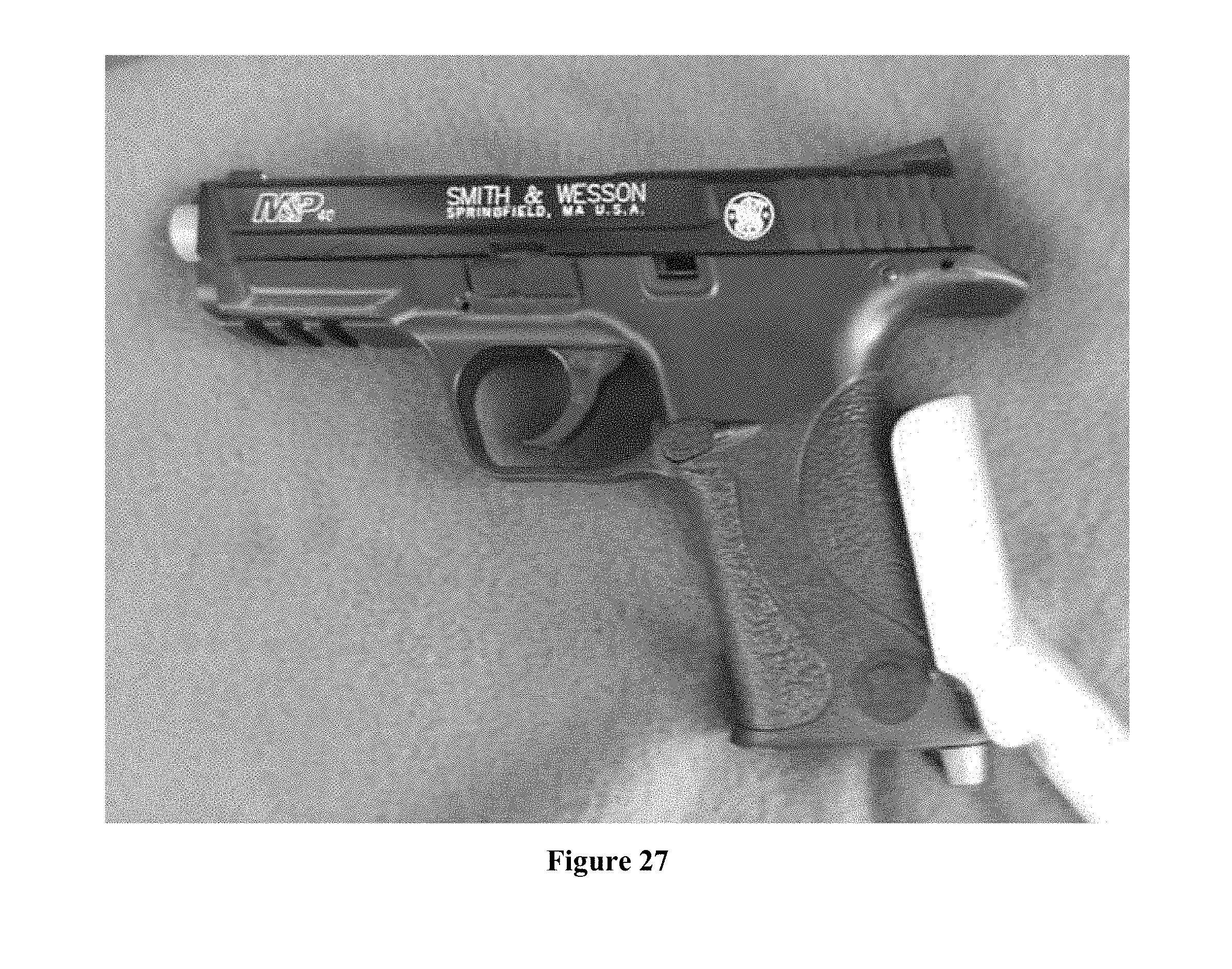
[0098] FIG. 16 is a Right view of Tee Shaped Brace (Type 1) with Optional Strap Attached. Depicted mounted on Tube with Ergonomic improvements.
[0099] FIG. 16 illustrates Tee-shaped braces. Designs may include angles other than a hard 90-degree Tees. Tee may or may not include a short length of tube (in the open ends) for appearance and/or more surface area contact. The short length may or may not include the means for storage inside one or both tubes connected to the Elbow. May utilize other fittings or devices for tool-free removal of cover, or a shaped cap that can be secured and removed without tools. Brace, cover, and fittings can be constructed of metals, polymer, rubbers or other materials. Brace may be attached to a Buffer Tube or other shaped length via threads, by mechanical tightening around the buffer tube, welding (or other means of adherence such as chemical bonding agents), mechanical means including, but not limited to, set screws. Designs may or may not include ergonomic changes or changes in physical dimensions.
[0100] Note 1: Note Ergonomic improvements may or may not be included.
[0101] FIG. 17 is a Right-Hand View of Sliding Brace in Collapsed Position utilizing an Elbow Brace in this Photo (but intended for any type brace). Sliding brace to include both inner tubes to be smaller than outer tube, and outer tube to be smaller than inner tube. May include more than 2 tube lengths. May incorporate mechanisms to lock or fix in open/extended position, collapsed position, and intermediate positions between fully expanded and fully collapsed. Materials may be metal, polymer, or other. Designs may be for a sliding Buffer tube.
[0102] FIG. 18 is a Drawing of Left-Hand View of Unmodified M-4 Stock in Preparation to become a Modified Brace Chassis, and an Unmodified Buffer Tube.
[0103] FIG. 18: Unmodified M-4 Stock and Full-Sized Buffer Tube. Note White outline of Buffer Tube (same as orange colored buffer tube in drawing. Note red line for a proposed cut location). Black Dashed lines represent Brace Chassis cuts for currently constructed Brace Chassis.
[0104] This model is similar to the Brace Chassis and Buffer Tube seen in FIG. 1. The main differences are that this Buffer Tube may be significantly shortened and the Brace Chassis has different dimensions (it is larger). The purpose of these changes is for aesthetic and support--to ensure that the Buffer Tube does not extend past the rear-most portion of the Brace Chassis when the Brace Chassis is in the collapsed position. This model will also facilitate the use of wider and or heavier straps for securing to the user's forearm.
[0105] FIG. 19 is a Drawing of Left-Hand View of Unmodified M-4 Stock in Preparation to become a Modified Brace Chassis, and a modified Buffer Tube. The Pen Depicts a Point of Modification to the Stock (soon to be Brace).
[0106] Note 1: Pen Depict one possible cut point.
[0107] Note 2: Buffer Tube (white template) has been folded down to one potential new length.
[0108] FIG. 20: Drawing of Left-Hand View of Modified Brace Chassis (formerly an Unmodified M-4 Stock) and a Modified Buffer Tube (shortened), Shown in the Fully Extended Position
[0109] FIG. 21 is a Drawing of Left-Hand View of Modified Brace Chassis (formerly an Unmodified M-4 Stock) and a Modified Buffer Tube (shortened), Shown in the Collapsed Position.
[0110] FIG. 21 depicts rear of stock removed to create Modified Brace Chassis. Depicted both in the extended and the collapsed positions.
[0111] Note 1: Shorter Buffer Tube and fold in paper depicts end of Modified Brace Chassis.
[0112] Note 2: Locations for cuts of Buffer tube and Brace Chassis may be changed for overall length, ergonomics, aesthesis, or operation, or other design basis. Other components may be shortened to allow more adjustment in length and still maintain the same overall length from the trigger to the rear-most portion.
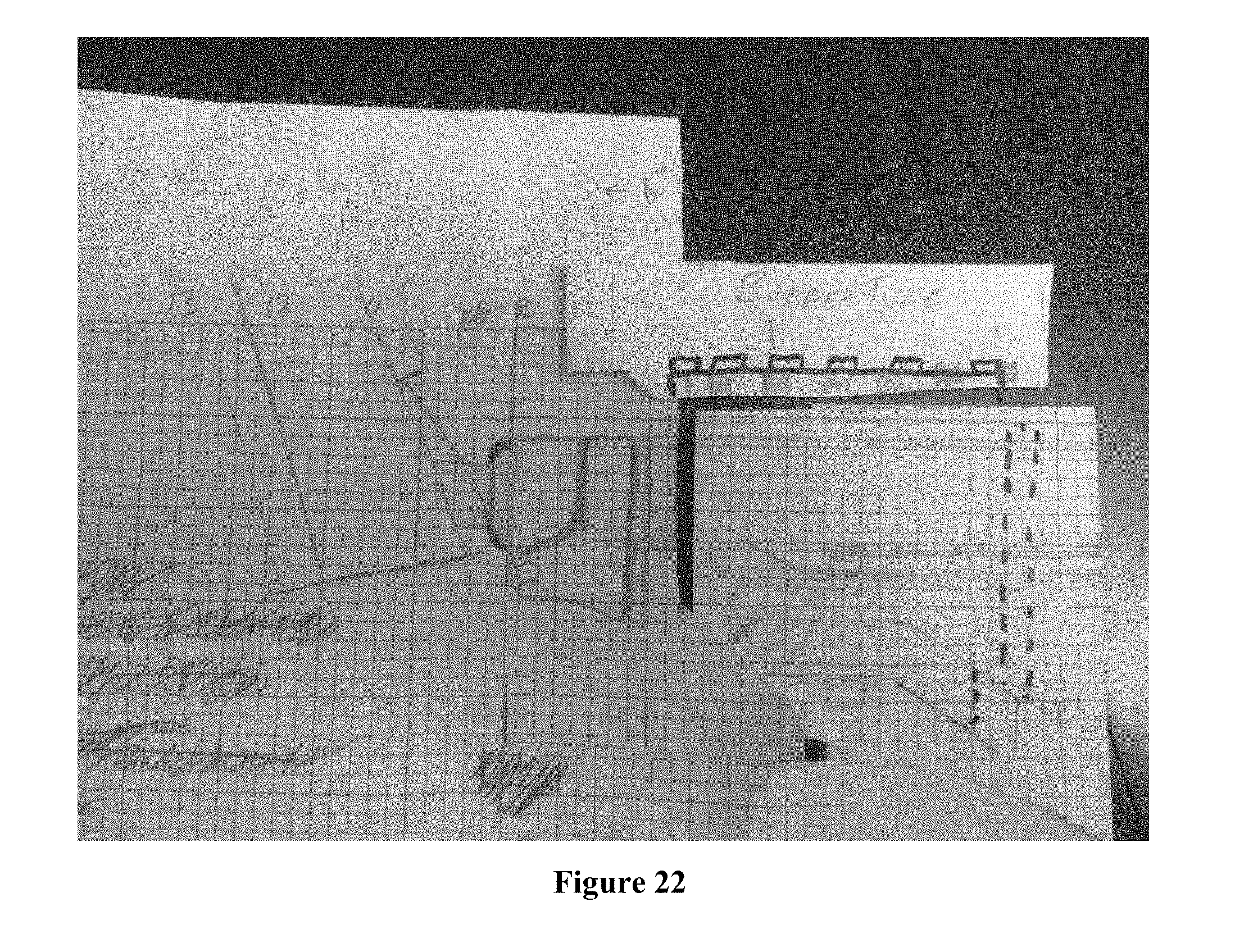
[0113] FIG. 22 is a Drawing of Left-Hand View of Modified Brace Chassis (formerly an Unmodified M-4 Stock) and a Modified Buffer Tube (shortened), Shown in the Collapsed Position. Brace Chassis has been shortened from both the Front and the Rear.
[0114] FIG. 22 shows rear of stock removed and Front of stock removed to create another version of the Modified Brace Chassis. Depicted only in the fully collapsed position.
[0115] Note 1: Shorter Buffer Tube.
[0116] Note 2: Locations for cuts of Buffer tube and Brace Chassis may be changed for overall length, ergonomics, aesthesis, or operation, or other design basis. Other components may be shortened to allow more adjustment in length and still maintain the same overall length from the trigger guard to the rear-most portion.
[0117] FIGS. 23-27 relate to Grip Connection Points.
[0118] Grip Panel Type mounts--Mount via removable Grip Panels. Entire replaceable grip for use with handguns similar to Dan Wesson Revolvers, T. C. Contenders, Ruger Blackhawks, 1911, Beretta M9, Desert Eagles, etc. Also includes guns with removable grip inserts (for example Gen 4 Glocks, S&W M&P version 2, Springfield's, etc.
[0119] An alternative to the Grip Panel Type mounts would be a "Main Spring Housing/Rod". This would come directly under the user's forearm (or may utilize an offset to run along the bottom-side of the user's forearm (in a similar location to the Grip/Rod models).
[0120] Slug-Plug type mounts--Mount via holes/voids in the Grip (typically referred to as a "Slug Plug Hole" or "Lanyard Hole").
[0121] Universal type mounts--Intended to fit most handguns (revolver, single shot or Semiautomatic) from Single stack .22's to double stack .45's. May utilize a single or double (opposing) shaped angle bar shaped components (not limited to geometry). Universal type mounts may also utilize a single shaped unit intended to flex on the sides to fit various widths, or this type may be custom shaped to fit specific handguns.
[0122] Non-serialized frames with integral Rods built into the frame. Guns such as the Sig 320, Honor Guard and others where the serial number is not on the traditional "Frame". Replacement frames can be purchased as a part rather than a firearm. These replacement (or original from the factory) frames will come either with the Rod directly attached or the means to attach a rod to the frame installed in the grip or other portion of the replacement grip module.
[0123] Serialized frames with integral Rod or integrated into the design for removable Rods built into the frame.
[0124] Custom molded sleeves that grips fit into, or mates next to the pistol. For example, remove the rubberized grip from a Ruger SR-22. Reinstall a new grip (constructed of various materials including but not limited to metals, polymers, rubbers, etc.) with either the Rod permanently attached or the means to attach a Rod to the grip with e Rod being removable.
[0125] All types can utilize straps, mechanical fasteners or other means for mounting to or mating next to the pistol.
[0126] Note: All Braces may utilize an offset in the Rod to allow the Rod and Buffer Tube to run at the 6 O'clock position (or other positions) directly below the center of the users forearm to utilize Brace types that mounts vertically over and/or around the user's forearm.
[0127] Note: Some Grip Connection Points may utilize a rod that attaches directly to the bottom rear-center of the Grip area (for example, but not limited to the Universal Types and the Non-Serialized Frame types).
[0128] FIG. 23 shows a Grip Connection Point (for Right Handed Users) for a Single Action or Double Action Revolver Type Handgun. Shown with Bare Rod Pull Pin and Tube. Note this rod may or may not be the same Outer Diameter as a Buffer Tube to facilitate the use of these or any other Stabilizing Braces (even those manufactured by others). Note use of pull pin.
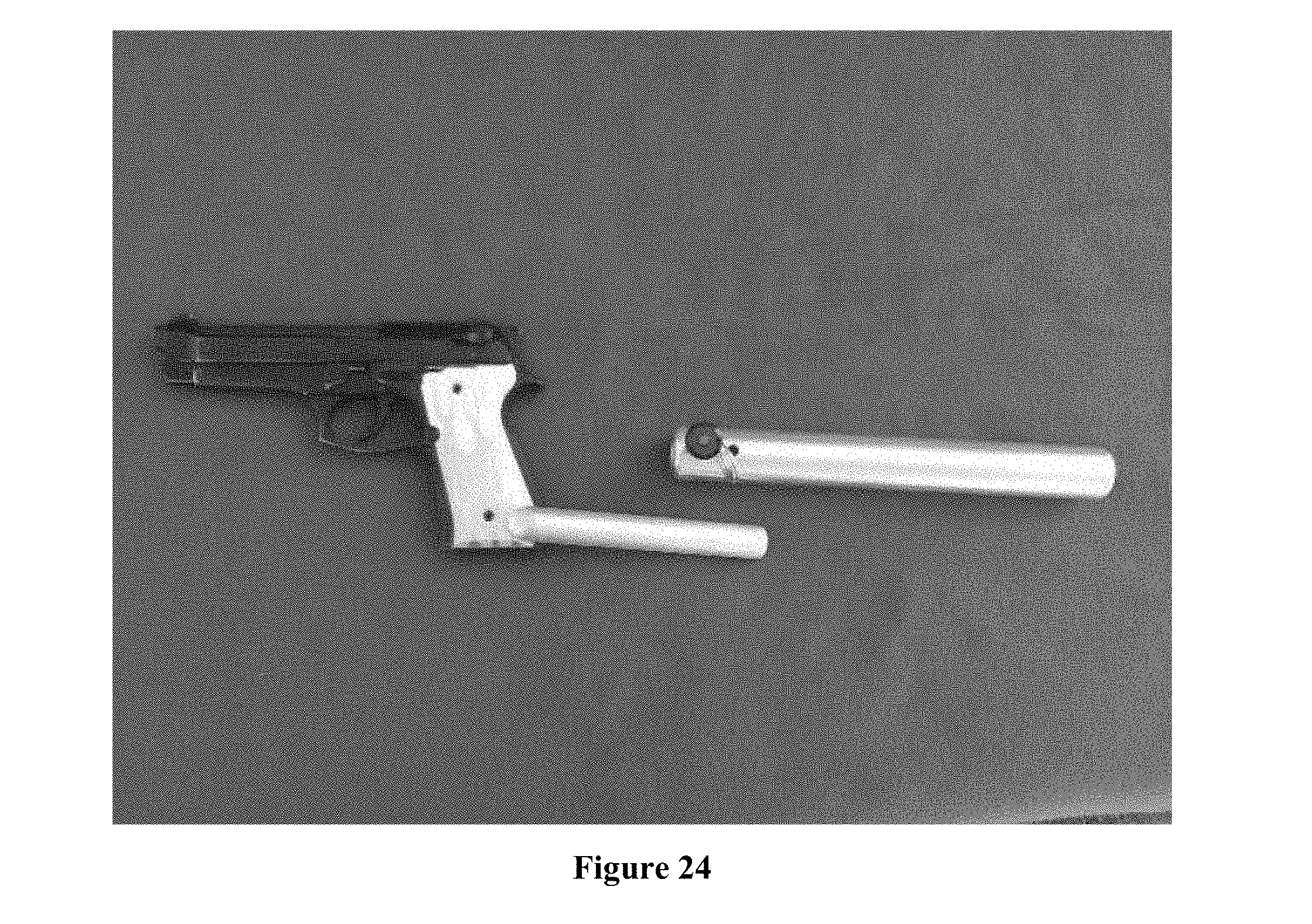
[0129] FIG. 24: Grip Connection Point (for Right Handed Users) for a Barretta M9/92 Type Handgun. Shown with Bare Rod (Rod not drilled for Pull Pin) Pull Pin and Tube.
[0130] FIG. 25: Grip Connection Point (Universal for handedness) Slug Plug Type for a Glock or other Handgun that accepts a "Slug Plug." Shown with Pull Pin and Tube. Note ability to install Pull Pin from right hand side or left-hand side. Retain the ability to put pull pin in any orientation.
[0131] Note 1: This photo and multiple photos depict an alternate Brace System that will be discussed further (it is a Tube type Brace System)
[0132] FIG. 26: Grip Connection Point (universal for handiness or Right or Left Handed) for a Non-Serialized Frame Type Handgun, shown with Bare Rod. Note: Electrical tape is wrapped around the rod in an attempt to represent it as the same material and molded in one piece. Material of Grip and Rod may vary.
[0133] Modular and/or Replaceable Grips and Non-Serialized Grip "non-Frames". The entire brace grip etc. is replaceable for guns like Sig P320, Ruger American, Honor Guard, etc. with replaceable lowers.
[0134] FIG. 26--Non-Serialized Frame. Rod will be an integral part of the Frame, or the frame will be manufactured to accept the insertion and removal of the Rod. Rod can be either Centered at the rear-bottom-center of the grip or at either rear-bottom side (sides to suit Left-handed or Right-handed users).
[0135] FIG. 27 shows a side view of a Grip Connection Universal "U" Shaped (universal for handiness or Right or Left Handed). Note: Rod Depicted may or may not be in this orientation.
[0136] The Universal U shaped is intended to be constructed of Polymer (but may be constructed of another material) may be rigid or with a "memory" or insert to cause it to seek the smaller shape and allow it to accept larger guns. Sides to be flexible and hug to the sides of the pistol with or without a strap to further secure the handgun to the Grip Connection Point. This flexing will allow it to fit more types of handguns). Rod can be either Centered at the rear-bottom-center of the grip or at either rear-bottom side (sides to suit Left-handed or Right-handed users).
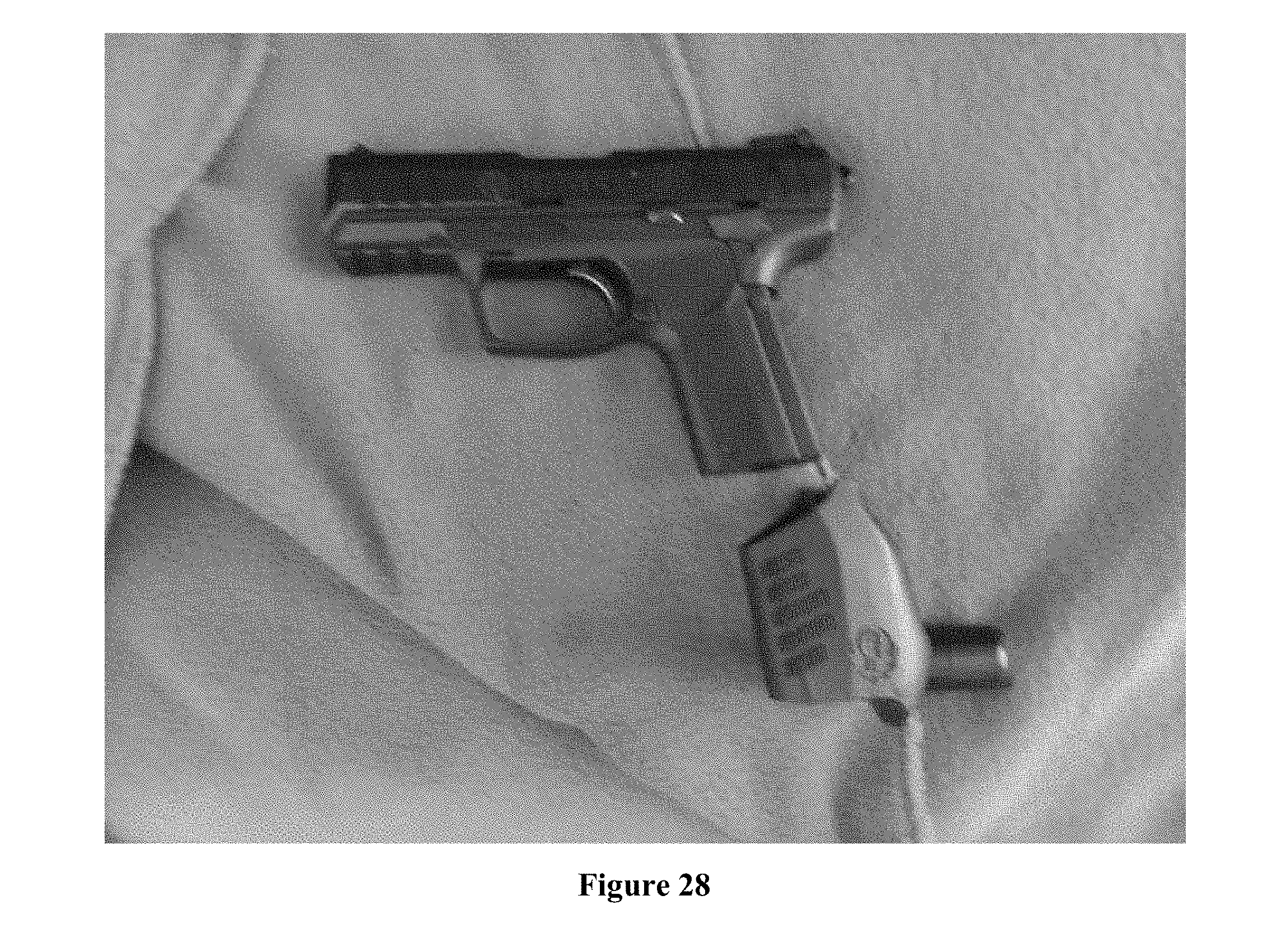
[0137] FIG. 28 shows a Grip Connection Grip Sleeve Model (universal for handiness or Right or Left Handed). The Grip and Rod Removed from Handgun Frame, shown with Bare Rod. A custom molded sleeve is illustrated that grips fit into, or mates next to the pistol. For example, remove the rubberized grip from a Ruger SR-22. Reinstall a new grip (constructed of various materials including but not limited to metals, polymers, rubbers, etc.) with either the Rod attached or the means to attach a Rod to the grip built into the grip. Depicted with Grip removed and installed. Rod can be either Centered at the rear-bottom-center of the grip or at either rear-bottom side (sides to suit Left-handed or right-handed users).
[0138] FIG. 29 illustrates a Hybrid Brace System (Note Tube on the handgun side of the AR Lower Remnant).
[0139] FIG. 29 is a Hybrid between the Tube Type Brace System and the Standard Buffer Tube Type Brace System. The Biggest difference between the Buffer Tube Type Brace system is--This does not utilize the Remnant of an AR Upper, and does not utilize the Buffer Tube Liner. This system utilizes a Short Tube (to be welded to the AR Lower Remnant) and Drilled for a Pull Pin that will lock the Rod to the Tube.
[0140] This Brace system is cross compatible with the Tube Type Brace System
[0141] This Brace System consists of: [0142] The Grip Connection Points (can utilize all Grip Connection Point types) include Grip and Rod. The Rod associated with the Grip Connection Points is drilled for insertion of a 1/4'' Pull Pin (size may vary). Very Similar to Grip/Rod [0143] Tube--O.D matches the OD of a standard Buffer Tube O.D. The ID of the tube is roughly 3/4'' (for insertion of the Rod). This is accomplished with a shot length of Tube within tube for this example (may be one piece). The Tube is also drilled to accepts a 1/4'' Pull Pin. [0144] Pull Pin--A pull pin that can be inserted thru the Tube and the Rod to lock them together. This Tube allow the changeout between Different pistols with different Grip Connection Points or to changeout different Tubes and Braces. The Pull Pin is such that is locks into place and only allows release if the push button is utilized. Different Pins, mechanical fatteners, or threaded/quick connections may also be utilized in lieu of a Pull Pin. [0145] Pull Pin can be in any arrangement (not just 3 O'clock to 9 O'clock). [0146] This Pull Pin is exactly the same Pin as those utilized in the Hybrid Brace System. Braces--May utilize any brace intended for a Standard Pistol Type buffer tube, or proprietary types. [0147] All materials and sizes may be changed. The Tube and Rods do not necessarily have to be round and can utilize different geometries to aid alignment and or prevent rotation.
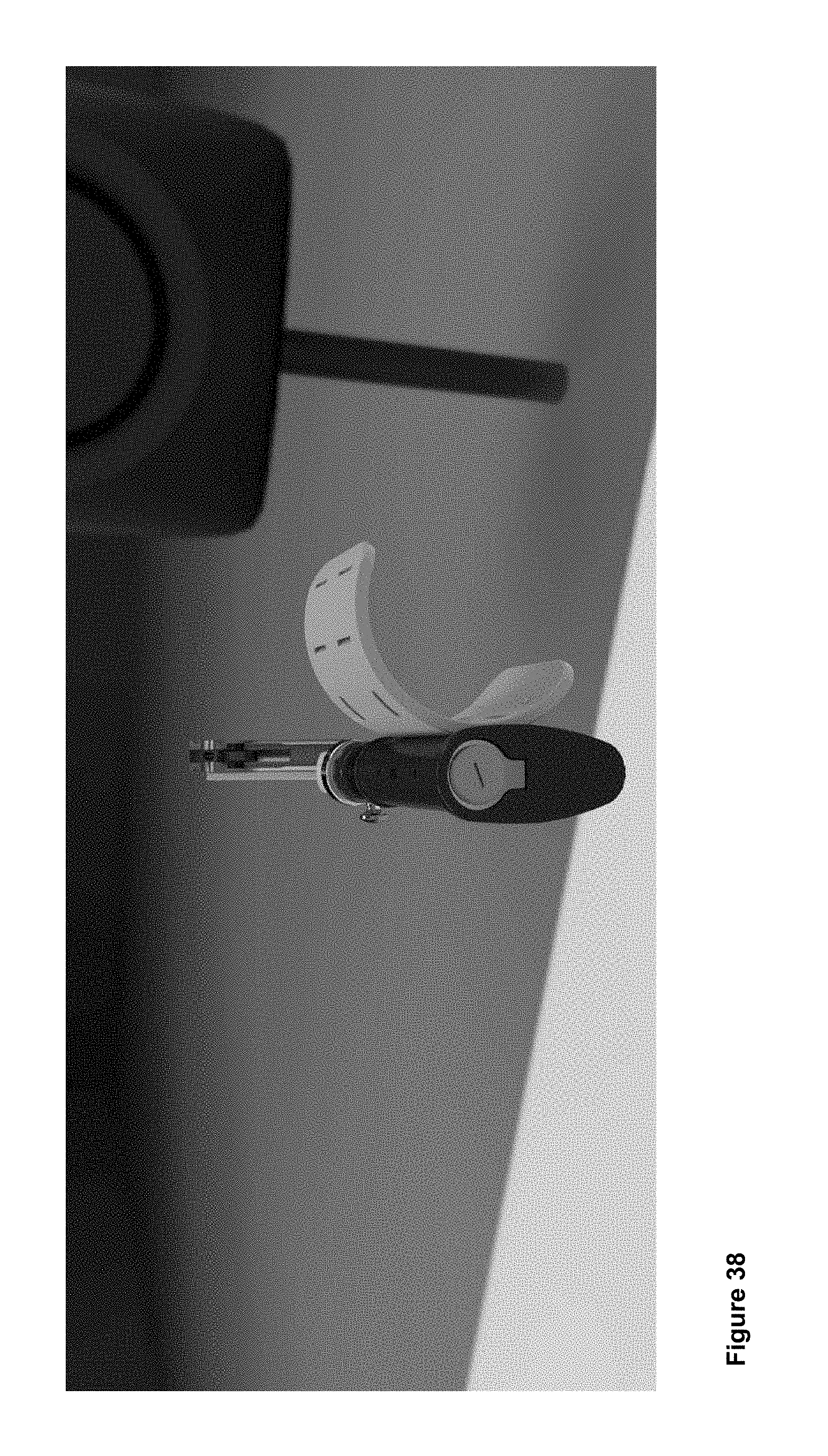
[0148] FIGS. 30 and 31 relate to a Tube Type (also identified as) Blood Stripe Line.
[0149] FIG. 30 shows a Blood Stripe Line.
[0150] The following components are shown starting at bottom left and moving Clockwise:
[0151] Handgun (normal with no accessories mounted) [0152] Grip Connection Point Double Angle Type with Rod and Optional Strap. Note holes drilled in both the left hand and right-hand angles for mounting of Rod. Holes allow for reversal for handedness (the Rod/Bolt joint also acts as the Adjustment Joint). Wing Nut or other Fastener for tightening and locking into position and loosening to change position. [0153] Tube with installed Pull Pin, and T Shaped Brace (with optional Strap installed). [0154] Bare Unmodified T Shaped Brace without optional strap. [0155] Grip Connection Point 1911 Type with hole drilled and Bolt installed. Bolt is for mounting to a Rod. [0156] Shown in Center--Rod with holes drilled for Connection Bolt to 1911 Type Grip Connection Point (depicted in photo) (Grip type may change to another Grip Type or Grip Connection Point), and for Pull Pin connection between Rod and Tube.
[0157] FIG. 30--Utilizing an aluminum 1911 grip. The grip is drilled thru and a threaded fitting (a nut (as is nuts and bolts), but not limited to a nut) is adhered to the interior surface of the handgun grip in a void created in the inside of the grip (against the handgun frame). The Rod (solid Aluminum with OD of .75'') is flattened (by milling stamping, etc.) or otherwise shaped on one extreme end--so that it lays nicely against the 1911 grip. The rod also has a hole drilled thru it in this flattened area corresponding to the hole drilled thru the grip and aligning with the nut inside the grip. The rod is attached to the grip via a fastener (picture a pan head screw or bolt). The rod inserts into the tube (OD of 1'' ID of .75''). The Rod is attached to the tube either by welding, the insertion of a removable pull pin (requires drilling of the Rod and tube), or other means. There are two separate models of the Rod--one that allows forward rotation and one that does not. Means for the rod to lock in the rearward (normal firing position) or the forward or front/folded position (for Storage and Transport) can be incorporated. The rod and tube can also be shapes other than round to ensure proper alignment (oval, with a channel in either component, square or other geometry), and to assist to prevent rotation. Channels or other mechanisms may also be utilized for alignment and anti-rotation purposes, or other purposes. Brace is installed either directly onto or into the tube or into a larger size tube or attached to a buffer tube. Can adapt to the non-Blood Stripe Series. Removal of the Bolt that adheres the grip to the Rod will allow normal holstering of the Pistol. The opposite Grip Panel will also be drilled and have a fitting (allowing to switch form right-handed to left handed without additional changes other than placing the Rod and associated fitting on the opposite side.
[0158] Also depicted is a universal type Grip but with holes drilled in both the left hand- and right-hand angle bar for mounting of the Rod. Fittings included to "Lock" the Rod at a specific angle but allow adjustment to other angles.
[0159] Braces are adaptable for Left- and Right-hand use.
[0160] This series can also utilize any braces in the Non-Blood Stripe series. Maximum effort has been put forth to ensure cross-compatibility where ever possible.
[0161] Pull Pin construction, type, location and angle of attachment may be changed. As well as the Type of fastener used.
[0162] FIG. 31 shows the "Folded for Storage and Transport" position.
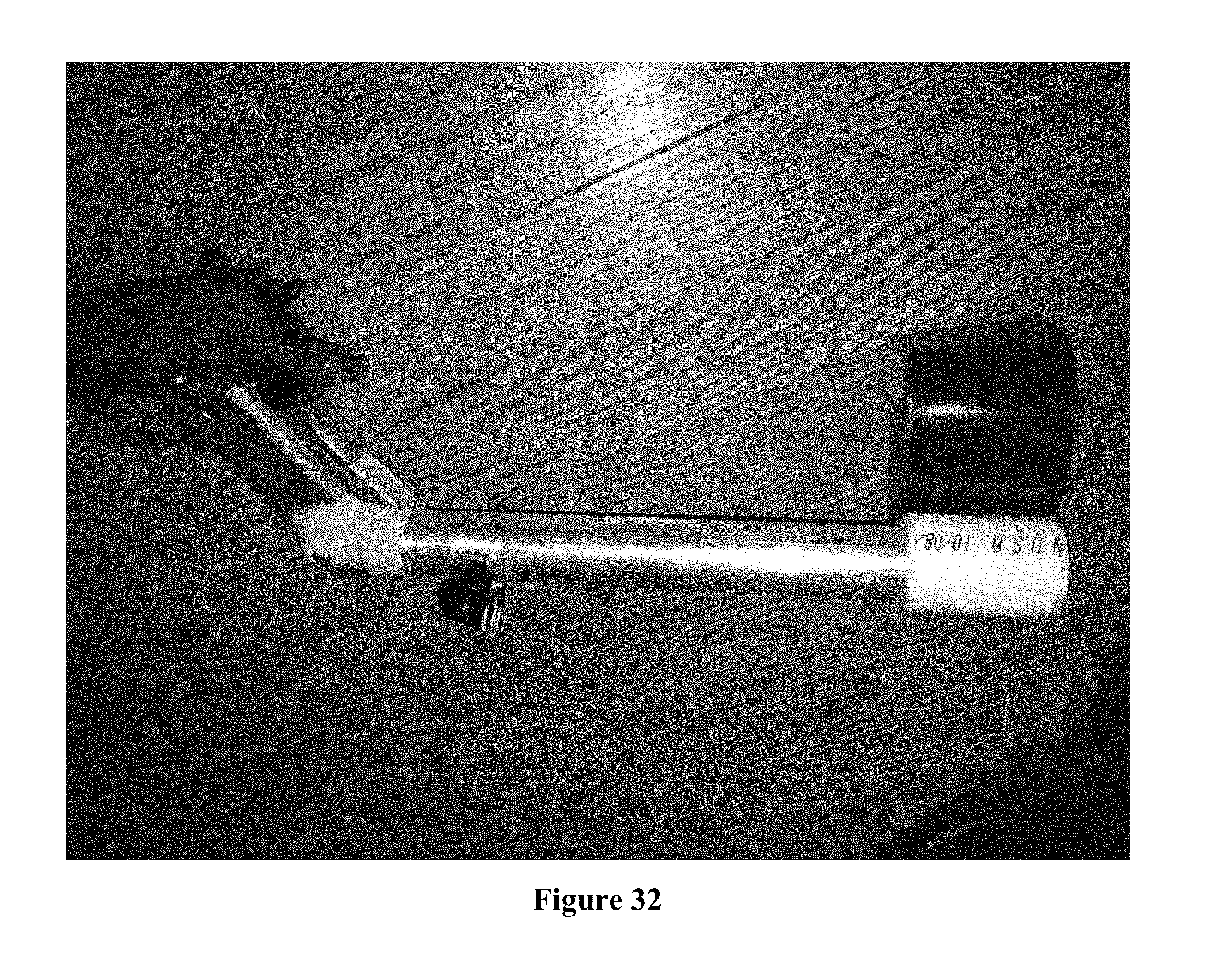
[0163] FIG. 32 shows a C-Shaped Brace and Brace Mounting Sleeve shown from the left-rear, it is adjustable for length.
[0164] Described from the Grip Connection Point going to the user:
[0165] Grip Connection Point--1911 Type with Adjustable Joint/Bolt. [0166] Rod (under Grey material, or Grip may be permanently attached to Rod, or directly to the Tube, or Permanently to the Tube via a Rod). [0167] Tube [0168] Pull Pin [0169] Brace Mounting Sleeve--Able to ride up and down the length of the Tube, allowing for adjustment to fit various users. With provisions to lock into place at various positions along the Tube. Brace mounting Sleeve and Tube OD may have different geometry and/or channels or other physical means to prevent rotation and aid alignment. Include provisions to allow sleeve to move and to be set and locked into various positions down the length of the Tube. [0170] C Shaped Brace--Mounted to the Brace Mounting Sleeve. This may be removable or a permanent part of the Brace Mounting Sleeve. Note Fittings between Brace and Sleeve. Fitting may vary. Location of the means to set the position of the Brace Sleeve anywhere around or on the Brace Locking Sleeve or Tube. [0171] May include combinations of components from Buffer Type, Hybrid, or Tube Type. Sliding Brace Chassis will have means for locking into various positions. Brace may or may not include straps. Bare Tube is also designed to be a Brace. Included provisions for Brace to switch from right-handed to left handed. [0172] NOTE: Grey material at the Rod/Brace junction should be ignored (other than to depict the ability to utilize Grip/Rod Combinations from other parts of this document. [0173] Tube and Grip may be an integral piece.
[0174] FIG. 33 shows a C Shaped Brace in use from the right of the user's perspective.
[0175] FIG. 34: Rendering 1.
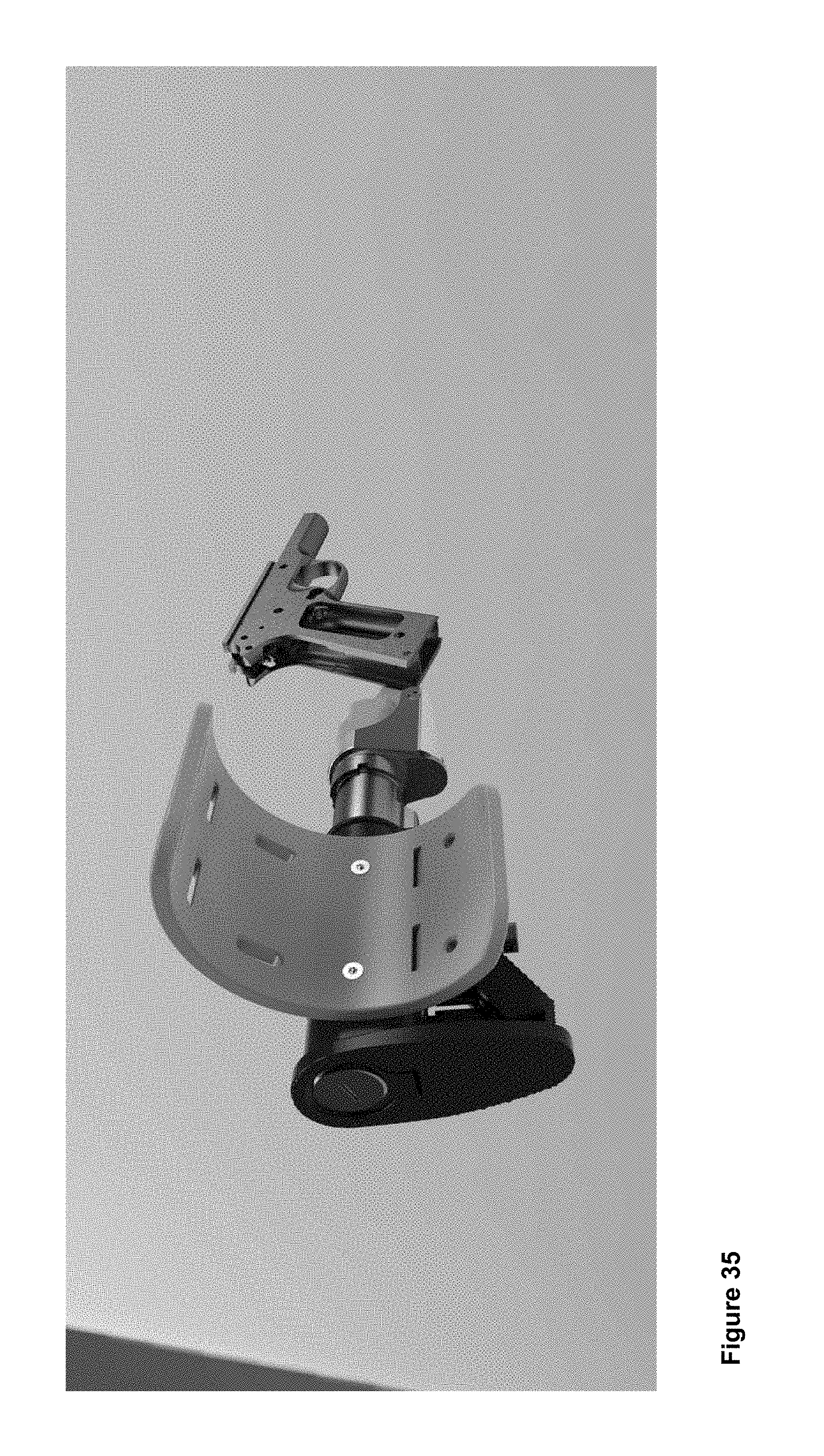
[0176] FIG. 35: Rendering 2.
[0177] FIG. 36: Rendering 3.
[0178] FIG. 37: Rendering 4.
[0179] FIG. 38: Rendering 5.
[0180] FIG. 39: Rendering 6 Extended.
[0181] FIG. 40: Coupler V2.
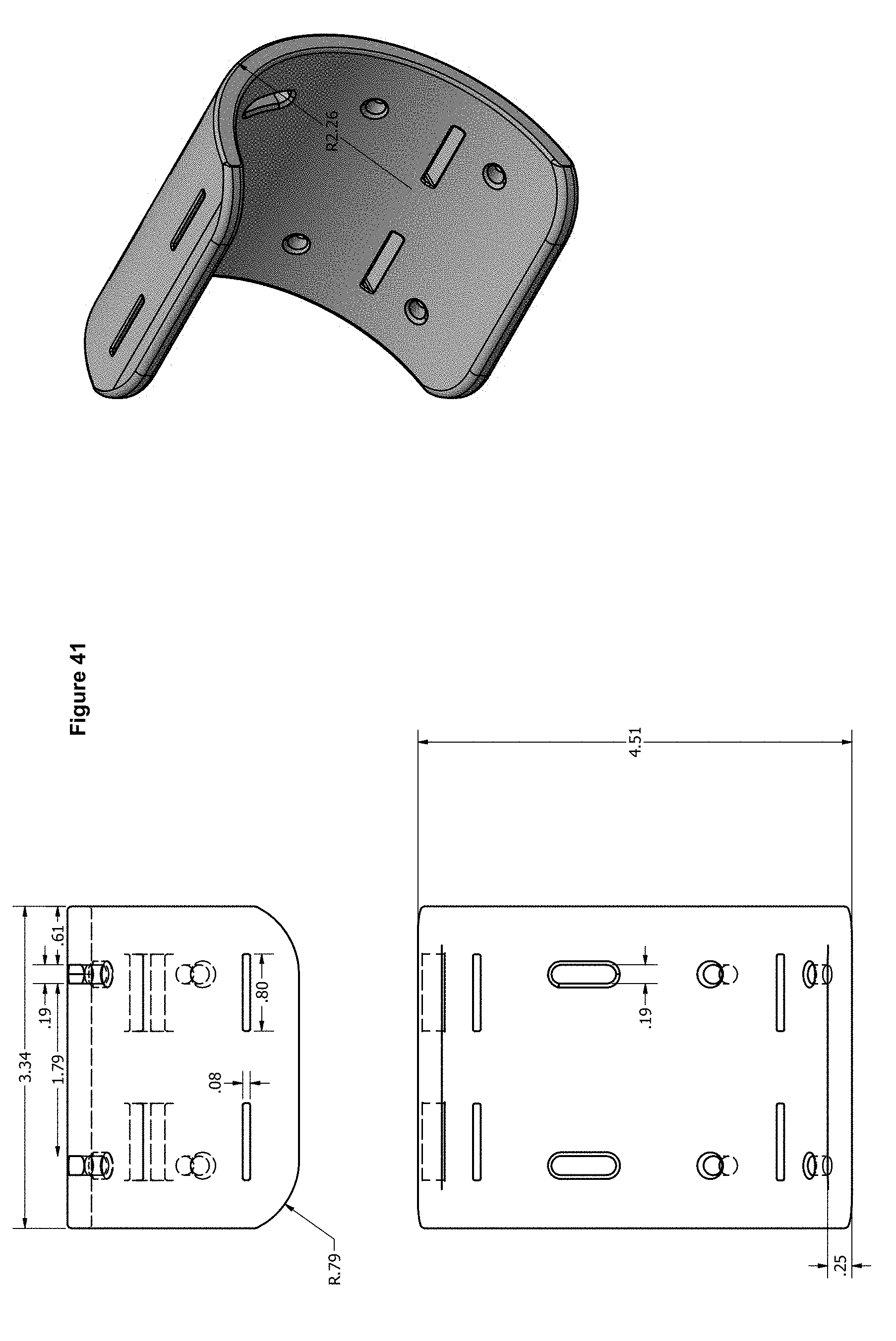
[0182] FIG. 41: Forearm grip V2.1.
[0183] FIG. 42: Fritz Assembly V2.1 Expanded.
[0184] FIG. 43: Fritz Assembly V2.2 Collapsed.
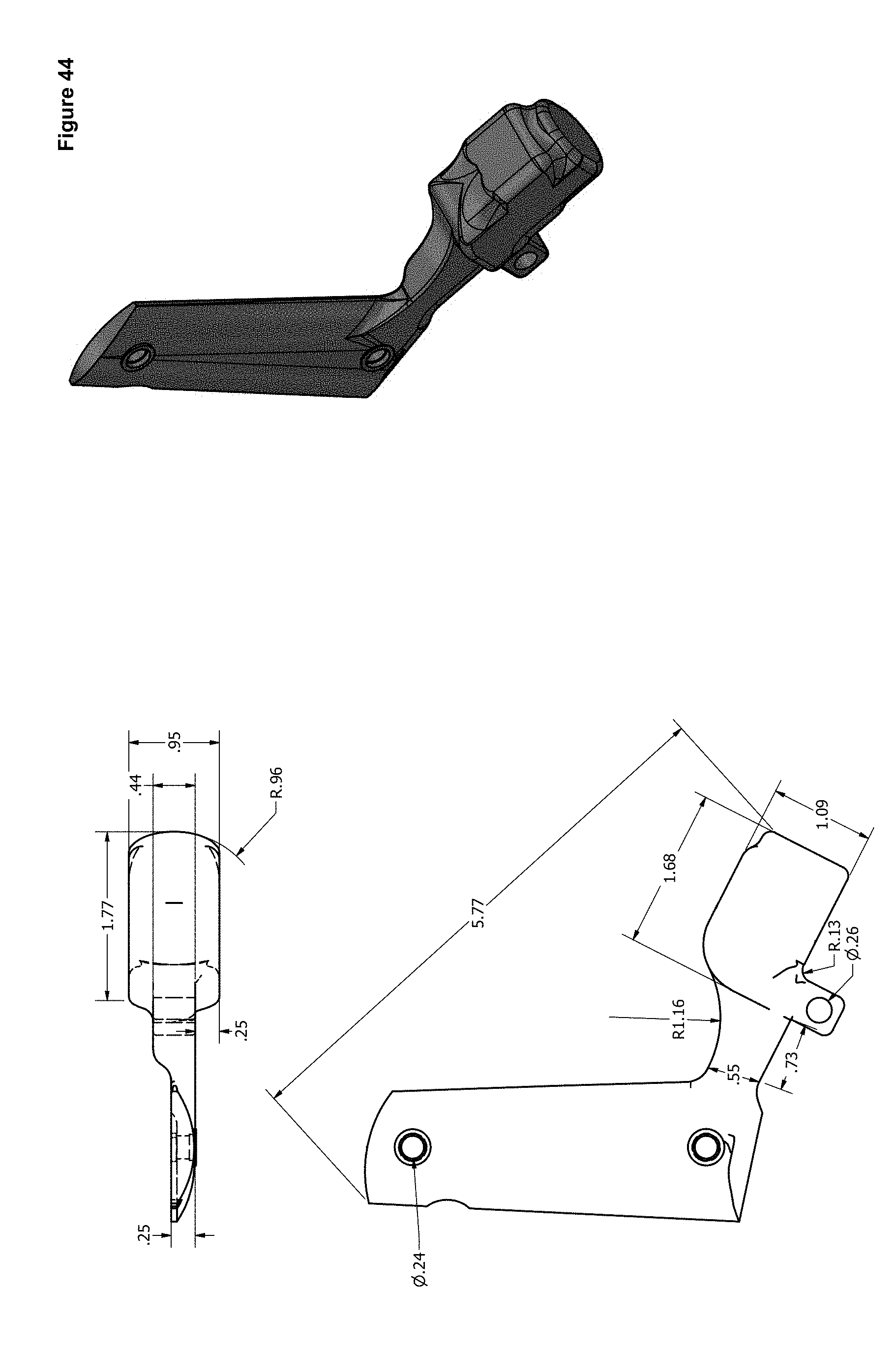
[0185] FIG. 44: Handgrip Right V2.1.
[0186] FIG. 45: Brace Chassis 2.1.
[0187] Benefits
[0188] The system has multiple and myriad benefits including, but not limited to:
[0189] More Secure Attachment:
[0190] The system facilitates a more secure attachment between the handgun and the user before, during and after the firing event.
[0191] Redistribution of Weight:
[0192] It assists to mitigate the weight of the handgun by redistributing a portion of the weight to the forearm.
[0193] Redistribution of Recoil:
[0194] To mitigate the effects of recoil directly applied to the hand by partially redistributing the recoil to the forearm.
[0195] More Accurate Shooting:
[0196] To increase accuracy of shots by increasing the contact area with the body and reducing the effects of human physiology, in particular eliminating the wrist's weakness and mobility.
[0197] Safety: [0198] More accurate shooting is inherently safer and also when used for hunting more accurate shots are more humane. [0199] Reduce and/or eliminate errant second shots with semi-automatics (a true safety concern).
[0200] Intended Users
[0201] Those suffering from reduced strength or reduced ability to withstand recoil.
[0202] Loss of digits (fingers and/or especially the thumb) or loss of a portion of the palm (combat veterans, industrial accident, any accident, or illness).
[0203] Those suffering from nerve pain/reduced feeling (nerve pain induced as a result of the recoil impulse).
[0204] Reduced capacity to handle recoil due to injury or illness (including Arthritis).
[0205] New users in training. This groups includes anyone new to shooting sports be it very young age or new to the sport at any age. The System assists with mitigating the violence of recoil, the weight of the handgun, retention, and eliminating errant second shots.
[0206] The effects of recoil are different on every person--The local police department here in my area has to regularly fail students out of their academy because they cannot become adjusted to recoil.
[0207] You have not lived until you have been on the firing line with a new user that drops a semi-automatic handgun after the first shot--yes it does happen.
[0208] Aged users or any users suffering from disabilities including but not limited to: arthritis, reduced or low strength, etc.
[0209] The inventor personally knows users that have either prematurely had to stop using their favored handguns (and move to progressively smaller calibers) or have exited the shooting sports entirely due to the effects of recoil as they age.
[0210] Large caliber handguns for hunters.
* * * * *
D00000
D00001
D00002
D00003
D00004
D00005
D00006
D00007
D00008
D00009
D00010
D00011
D00012

D00013

D00014

D00015

D00016

D00017

D00018

D00019

D00020

D00021
D00022

D00023
D00024

D00025

D00026
D00027
D00028

D00029

D00030

D00031
D00032

D00033

D00034
D00035

D00036

D00037
D00038

D00039

D00040
D00041

D00042

D00043
D00044

XML
uspto.report is an independent third-party trademark research tool that is not affiliated, endorsed, or sponsored by the United States Patent and Trademark Office (USPTO) or any other governmental organization. The information provided by uspto.report is based on publicly available data at the time of writing and is intended for informational purposes only.
While we strive to provide accurate and up-to-date information, we do not guarantee the accuracy, completeness, reliability, or suitability of the information displayed on this site. The use of this site is at your own risk. Any reliance you place on such information is therefore strictly at your own risk.
All official trademark data, including owner information, should be verified by visiting the official USPTO website at www.uspto.gov. This site is not intended to replace professional legal advice and should not be used as a substitute for consulting with a legal professional who is knowledgeable about trademark law.