Ducted Firearm Suppressor
Hall; Lance
U.S. patent application number 16/283035 was filed with the patent office on 2019-08-22 for ducted firearm suppressor. The applicant listed for this patent is Lance Hall. Invention is credited to Lance Hall.
| Application Number | 20190257608 16/283035 |
| Document ID | / |
| Family ID | 67617666 |
| Filed Date | 2019-08-22 |




View All Diagrams
| United States Patent Application | 20190257608 |
| Kind Code | A1 |
| Hall; Lance | August 22, 2019 |
DUCTED FIREARM SUPPRESSOR
Abstract
A suppressor is provided to reduce the sound produced by a firearm. The Suppressor comprises a body with a muzzle attachment facility and the body defines a linear bullet passage with a bullet exit aperture. Further, the body of the suppressor defines an articulated gas path away from the bullet passage, and the gas path has a plurality of overlaying forward flow segments and rearward flow segments and an exit aperture away from the bullet exit aperture.
| Inventors: | Hall; Lance; (Toney, AL) | ||||||||||
| Applicant: |
|
||||||||||
|---|---|---|---|---|---|---|---|---|---|---|---|
| Family ID: | 67617666 | ||||||||||
| Appl. No.: | 16/283035 | ||||||||||
| Filed: | February 22, 2019 |
Related U.S. Patent Documents
| Application Number | Filing Date | Patent Number | ||
|---|---|---|---|---|
| 62633640 | Feb 22, 2018 | |||
| Current U.S. Class: | 1/1 |
| Current CPC Class: | F41A 21/30 20130101 |
| International Class: | F41A 21/30 20060101 F41A021/30 |
Claims
1. A firearm suppressor comprising: a body having a muzzle attachment facility; the body defining a linear bullet passage having a bullet exit aperture; the body defining an articulated gas path away from the bullet passage; and the gas path having a plurality of overlaying forward flow segments and rearward flow segments and an exit aperture away from the bullet exit aperture.
Description
CROSS-REFERENCE TO RELATED APPLICATIONS
[0001] This application claims the benefit of U.S. Provisional Patent Application No. 62/633,640 filed on Feb. 22, 2018, entitled "Ducted Firearm Suppressor", which is hereby incorporated by reference in its entirety for all that is taught and disclosed therein.
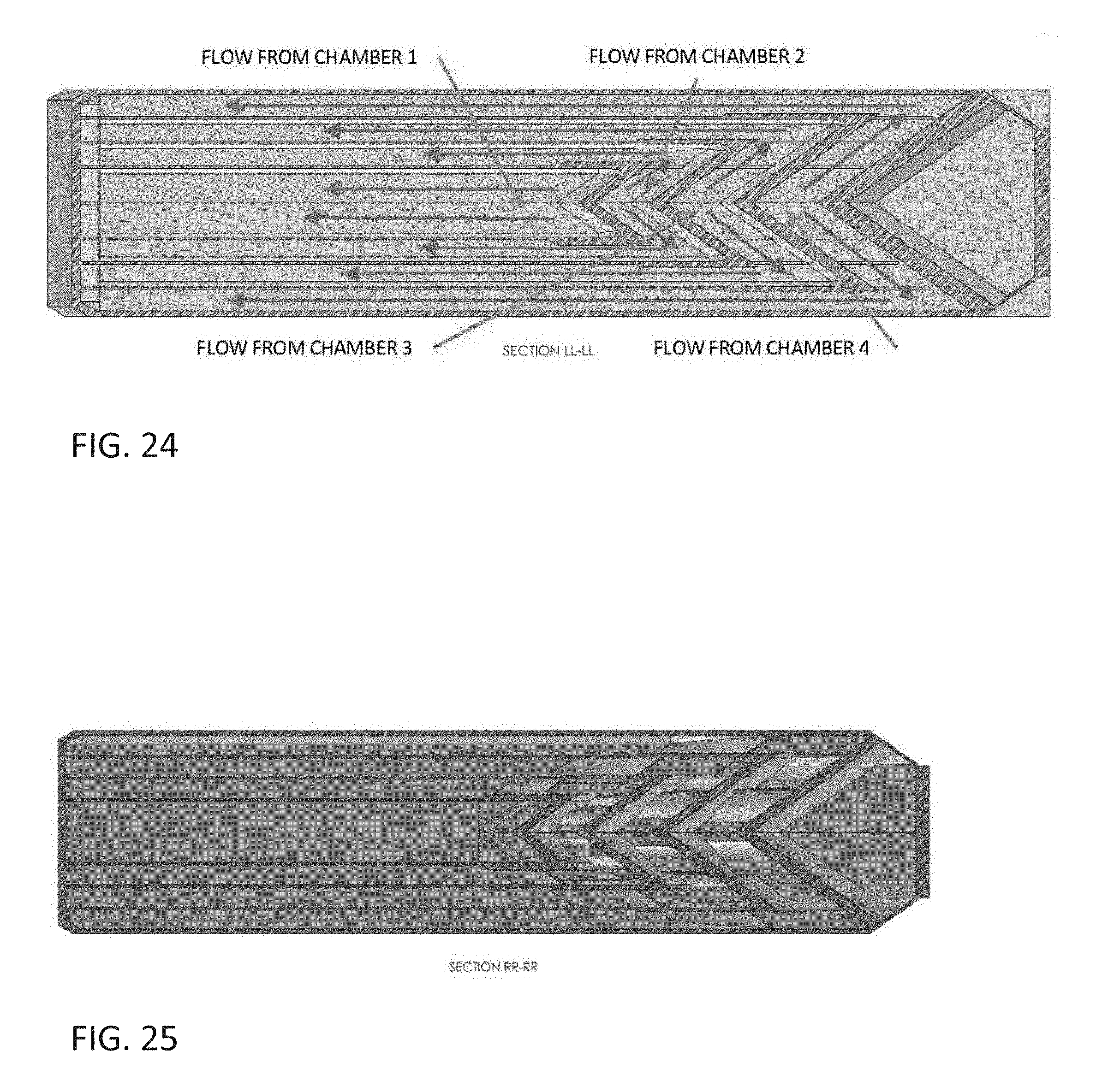
FIELD OF THE INVENTION
[0002] The present invention relates to a ducted firearm suppressor, and more particularly, to a suppressor that contains blast diversion features and reduces the sound produced by a firearm.
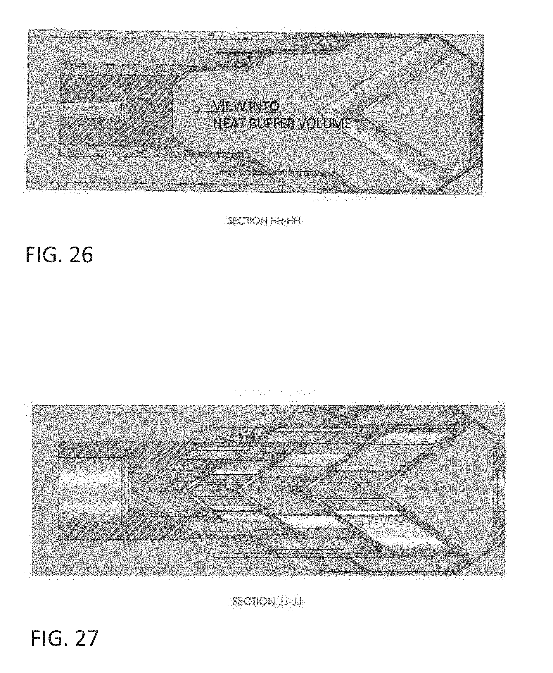
BACKGROUND OF THE INVENTION
[0003] Recent advancements in manufacturing technologies have expanded the design space of engineers. The ducted firearm suppressor described in this application relies on these new manufacturing technologies to be produced.
[0004] The limitations of the prior art are addressed by providing a suppressor to reduce the sound produced by a firearm. The Suppressor comprises a body with a muzzle attachment facility and the body defines a linear bullet passage with a bullet exit aperture. Further, the body of the suppressor defines an articulated gas path away from the bullet passage, and the gas path has a plurality of overlaying forward flow segments and rearward flow segments and an exit aperture away from the bullet exit aperture.
SUMMARY OF THE INVENTION
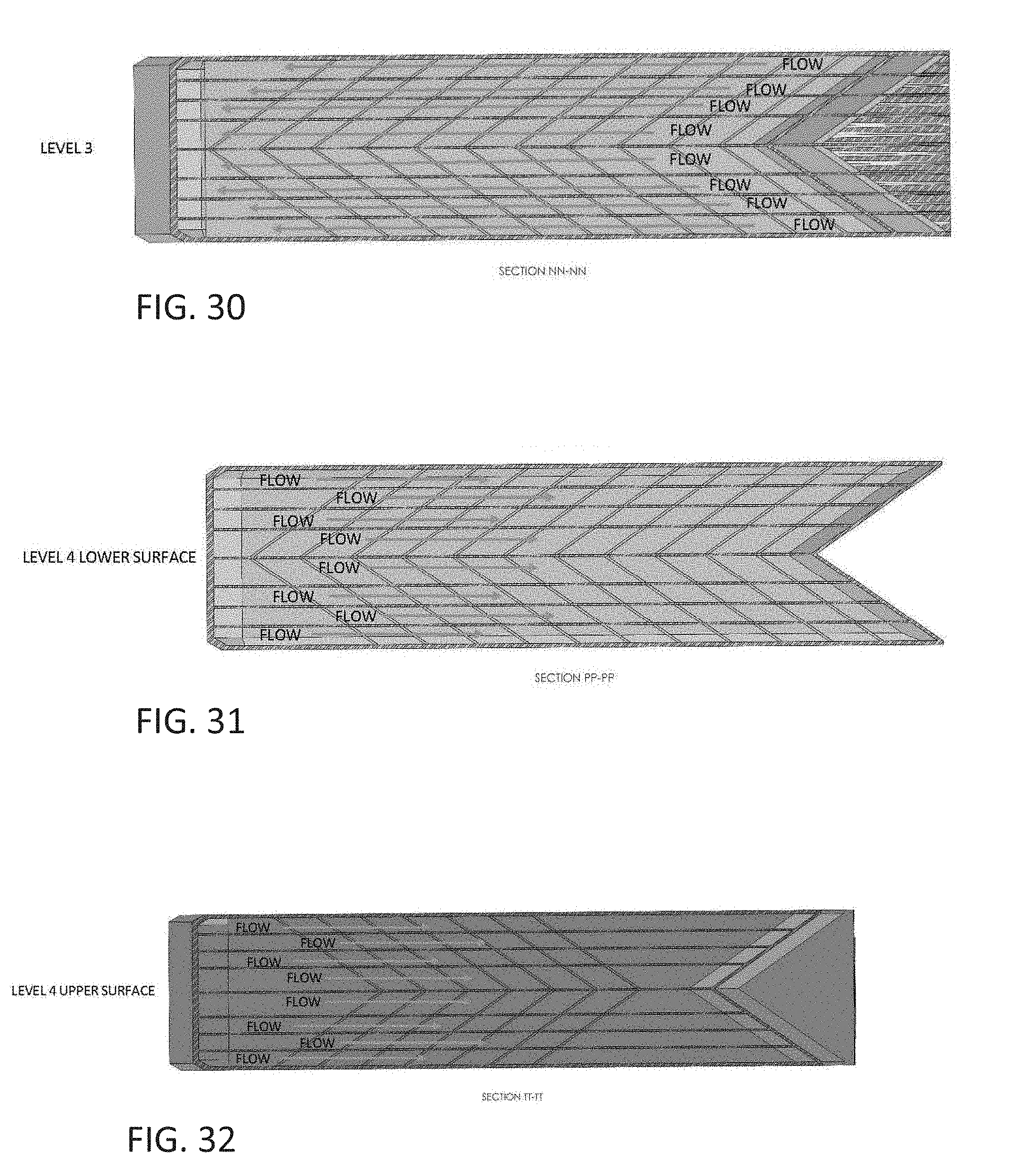
[0005] The present invention is intended to reduce the sound produced by a firearm as the blast exits the muzzle of the barrel.
[0006] The present invention consists of a body that contains blast diversion features and ducting that allow the blast pressure to dissipate over a longer period of time, cool to some extent, and exit through different openings than the projectile exit port.
[0007] The present invention and its manufacturing method allow for more compact applications as it reduces the overall length extension from the end of the barrel.
[0008] The present invention routes the blast gases via ducting under or around the barrel and allows the gases to flow freely as opposed to the traditional methods of containing the blast gases with various baffle designs.
[0009] The body of the present invention also has features to allow mounting to a firearm muzzle and can be configured to various mounting methods.
BRIEF DESCRIPTION OF THE DRAWINGS
[0010] FIGS. 1-32 show van of a preferred embodiment of the invention.
DETAILED DESCRIPTION OF A PREFERRED EMBODIMENT
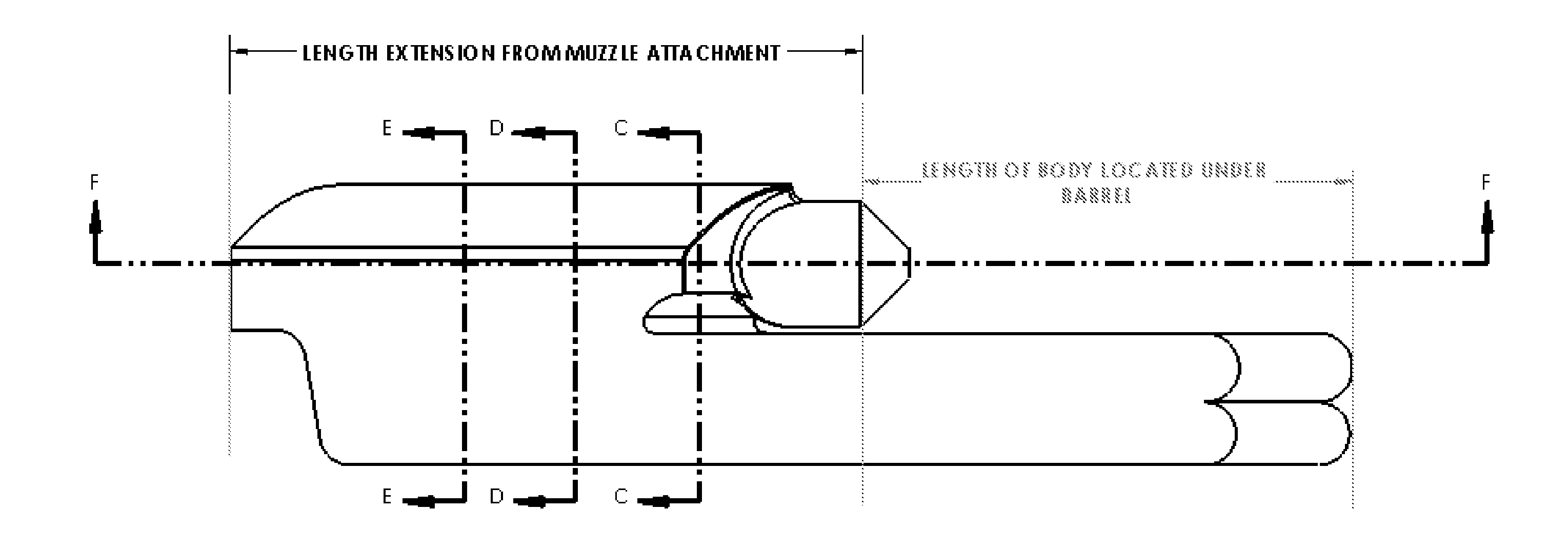
[0011] FIG. 1 is a top view of the device.
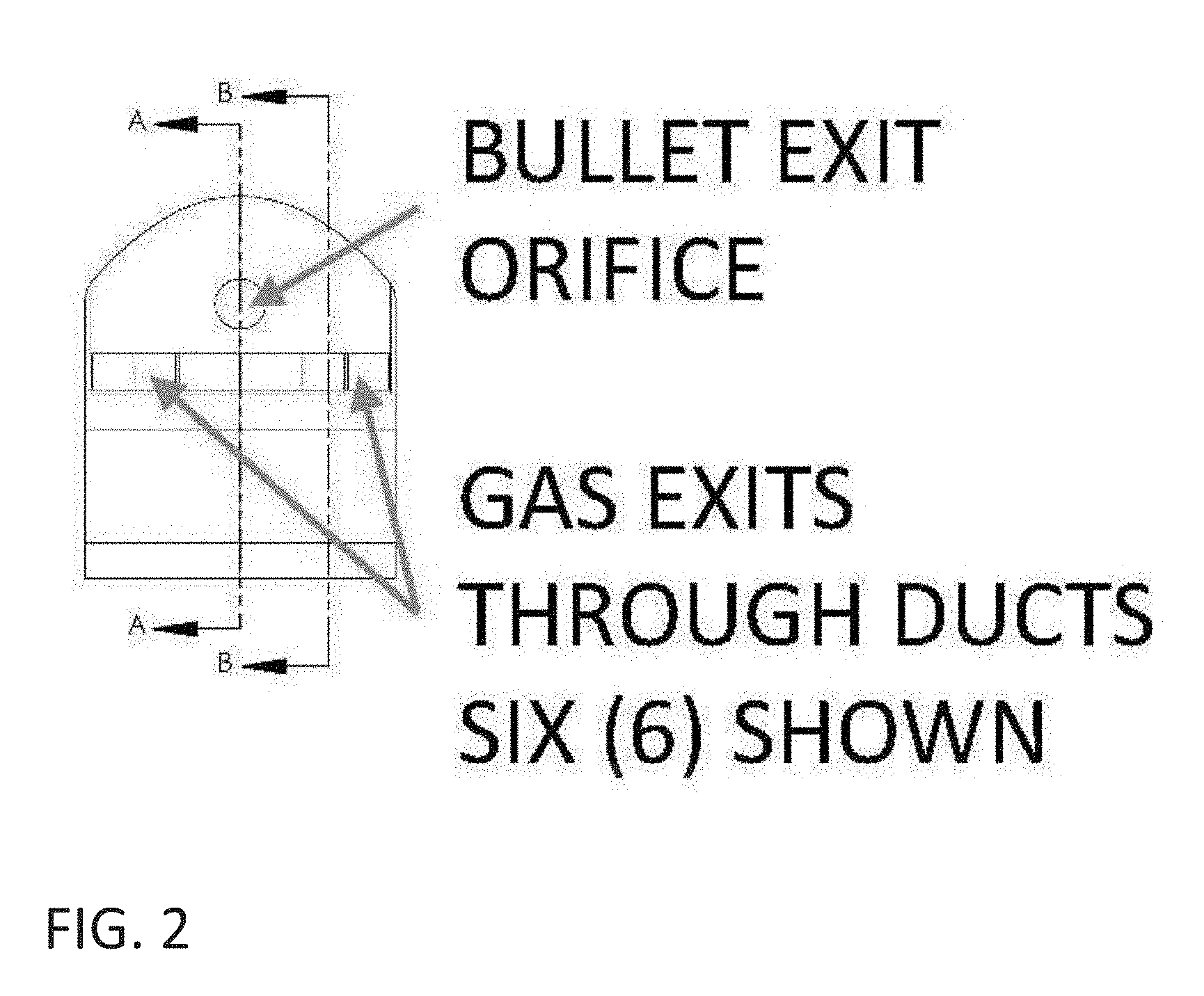
[0012] FIG. 2 shows the gas exit port locations relative to the bullet exit orifice.
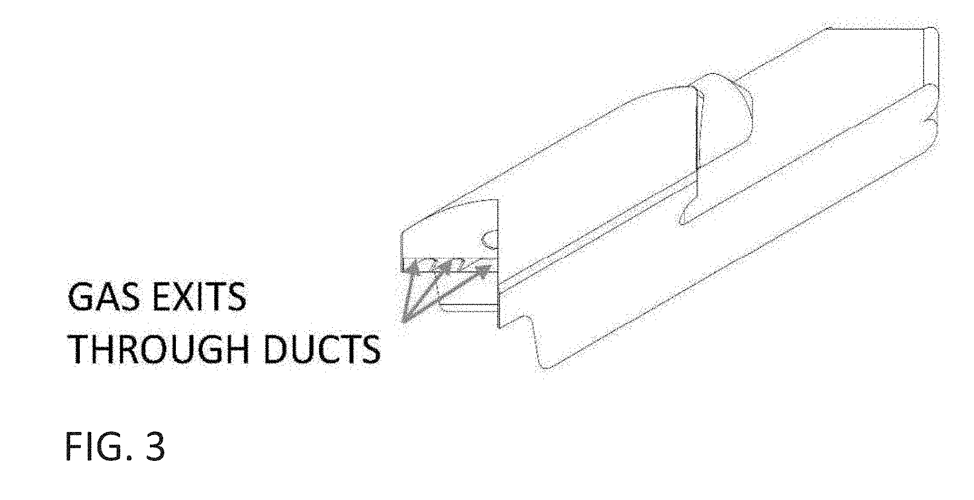
[0013] FIG. 3 is an isometric view of the invention and shows the gas exit ports.
[0014] FIG. 4 shows the relationship of the muzzle mounting location to the forward and rearward extents of the device.
[0015] FIG. 5 shows the bullet path through the device and details the diversion features' arc that is tangent to the bullet path
[0016] FIG. 6 is a section view of the bullet centerline looking downward into the diversion features. It also shows the flow of the gas as it impinges into the angled and curved diversion features.
[0017] FIG. 7 is a section view B-B of the device
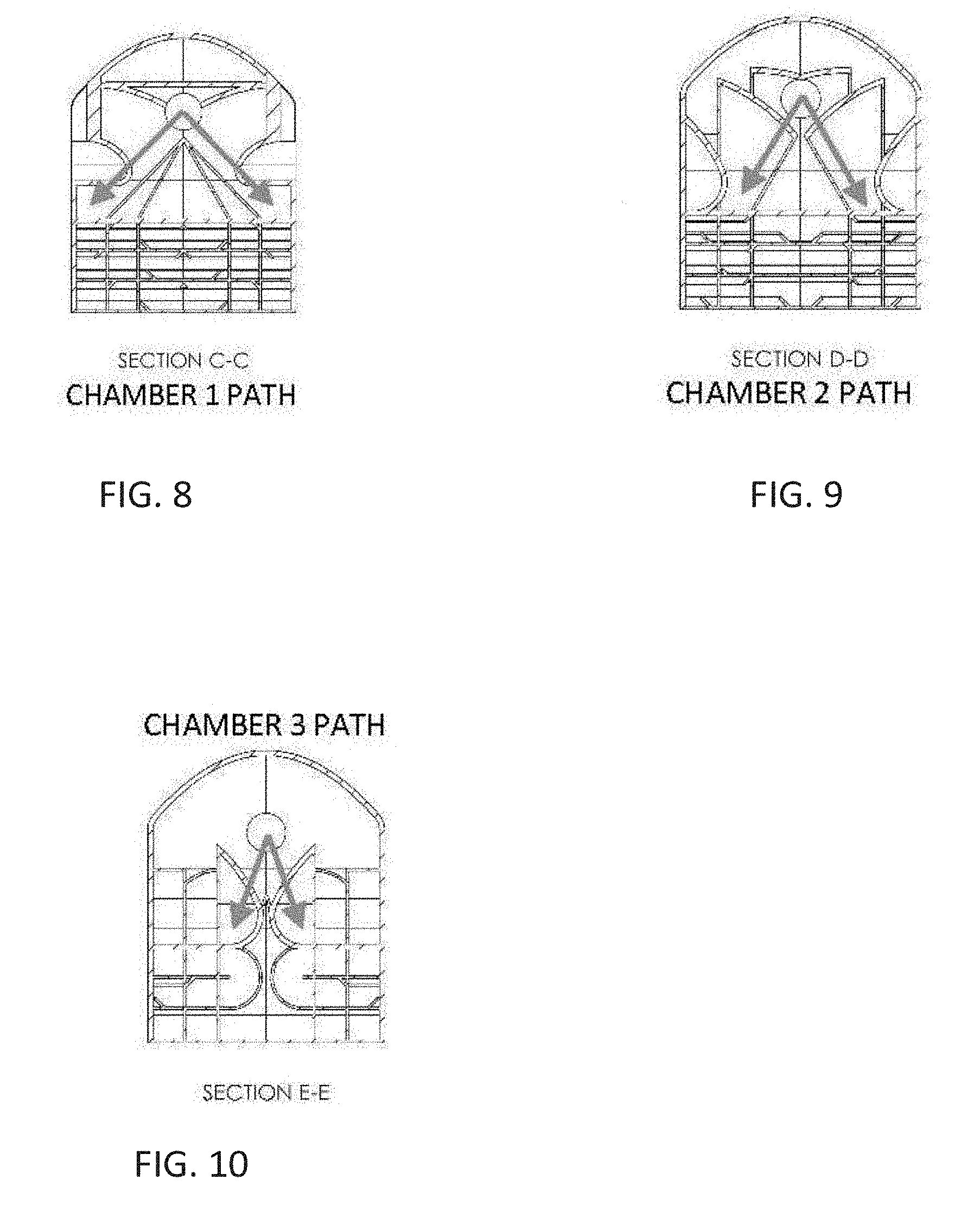
[0018] FIG. 8 is a section view C-C of the device and shoves the flow of gas into the outer passageways from the first chamber.
[0019] FIG. 9 is a section view D-13 of the device and shows the flow of gas into the passageways from the second chamber.
[0020] FIG. 10 is a section view E-E of the device and shows the flow of gas into the inner most passageways from the third chamber.
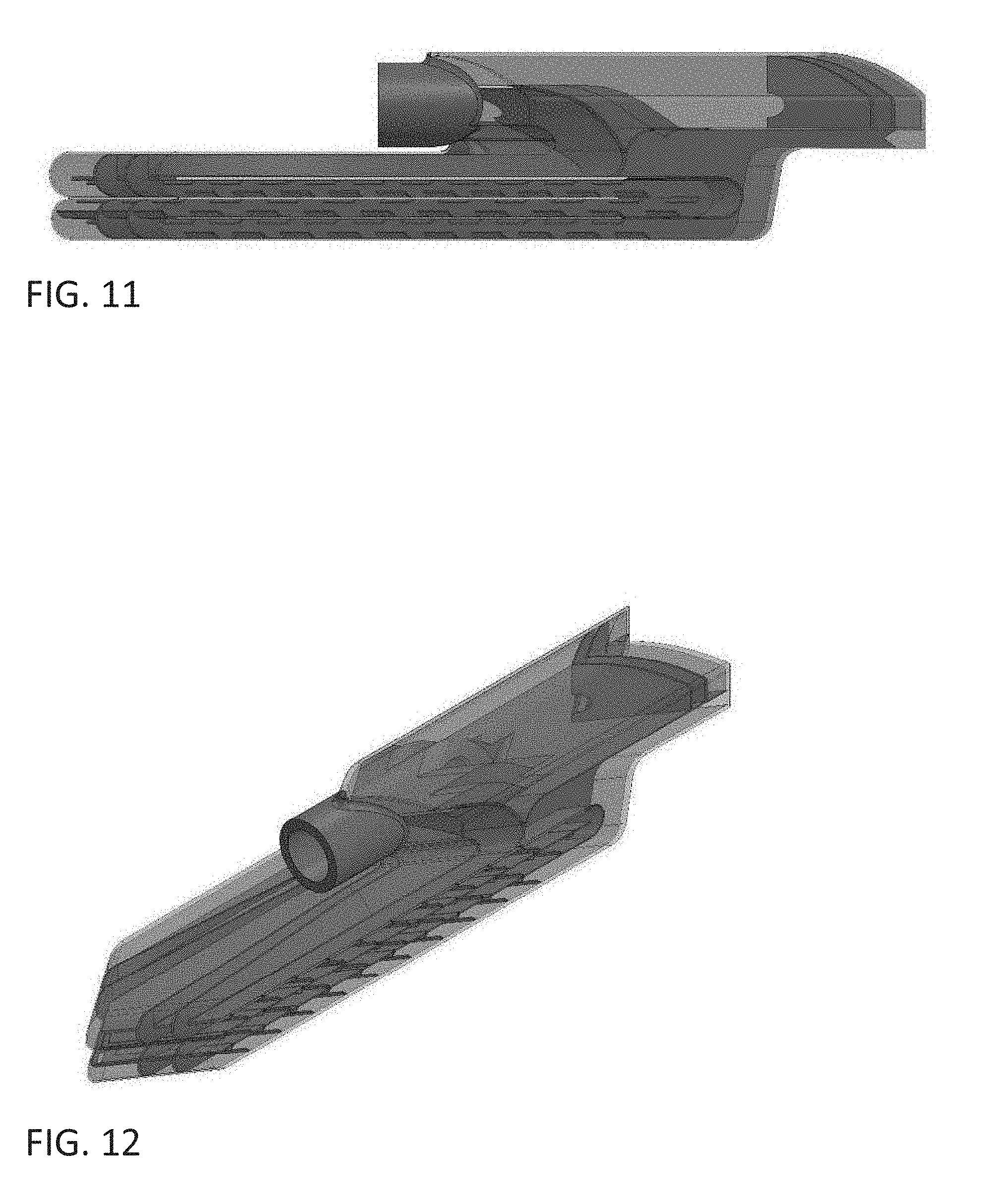
[0021] FIG. 11 is a side view of the device with a semi-transparent outer shell in order to show the inner structure.
[0022] FIG. 12 is a rear isometric view of the device with a semi-transparent outer shell in order to show the inner structure.
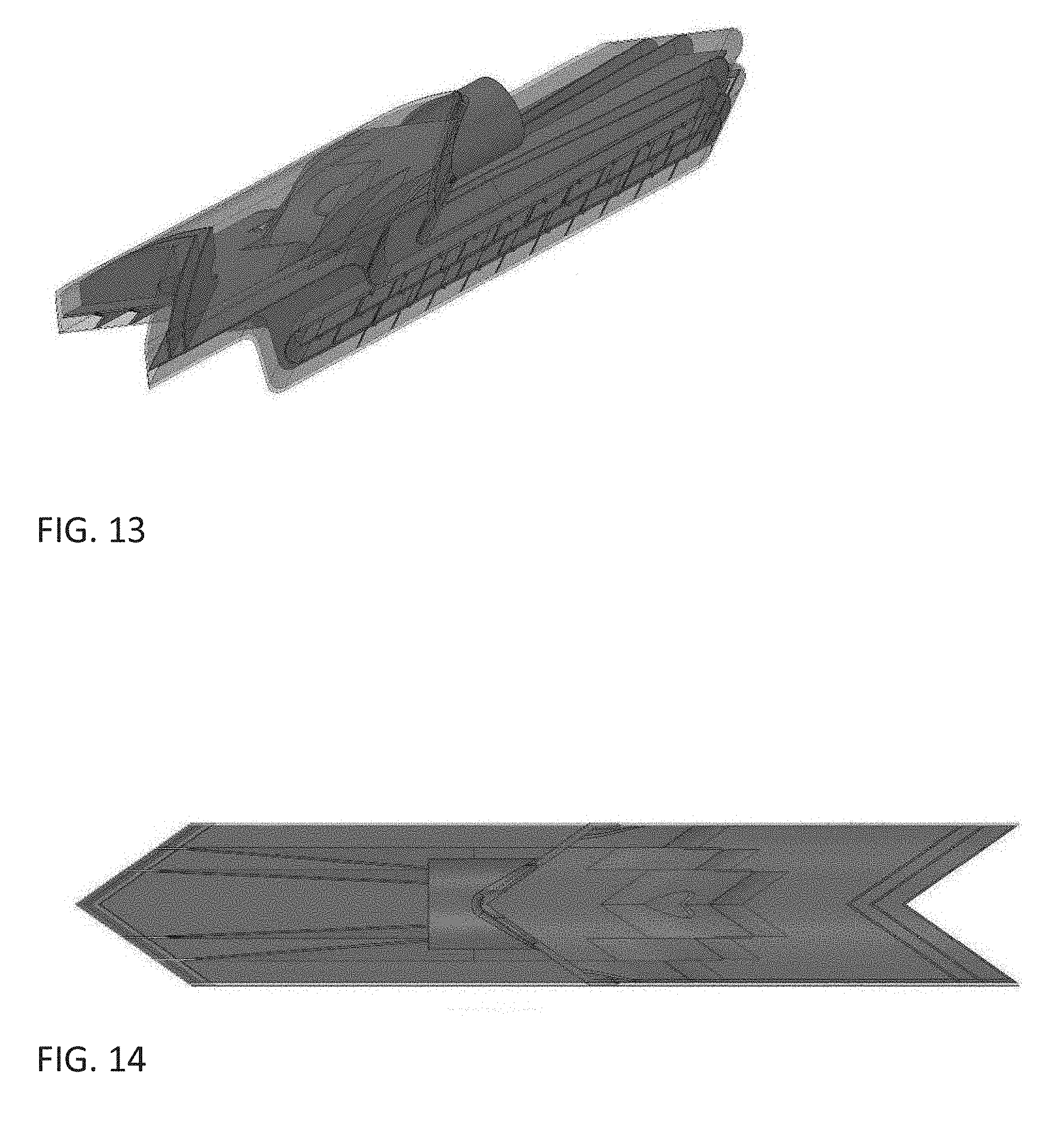
[0023] FIG. 13 is a front isometric view of the device with a semi-transparent outer shell in order to show the inner structure.
[0024] FIG. 14 is a top view of the device with a semi-transparent outer shell in order to show the inner structure.
[0025] FIG. 15 is a side view of another design variation.
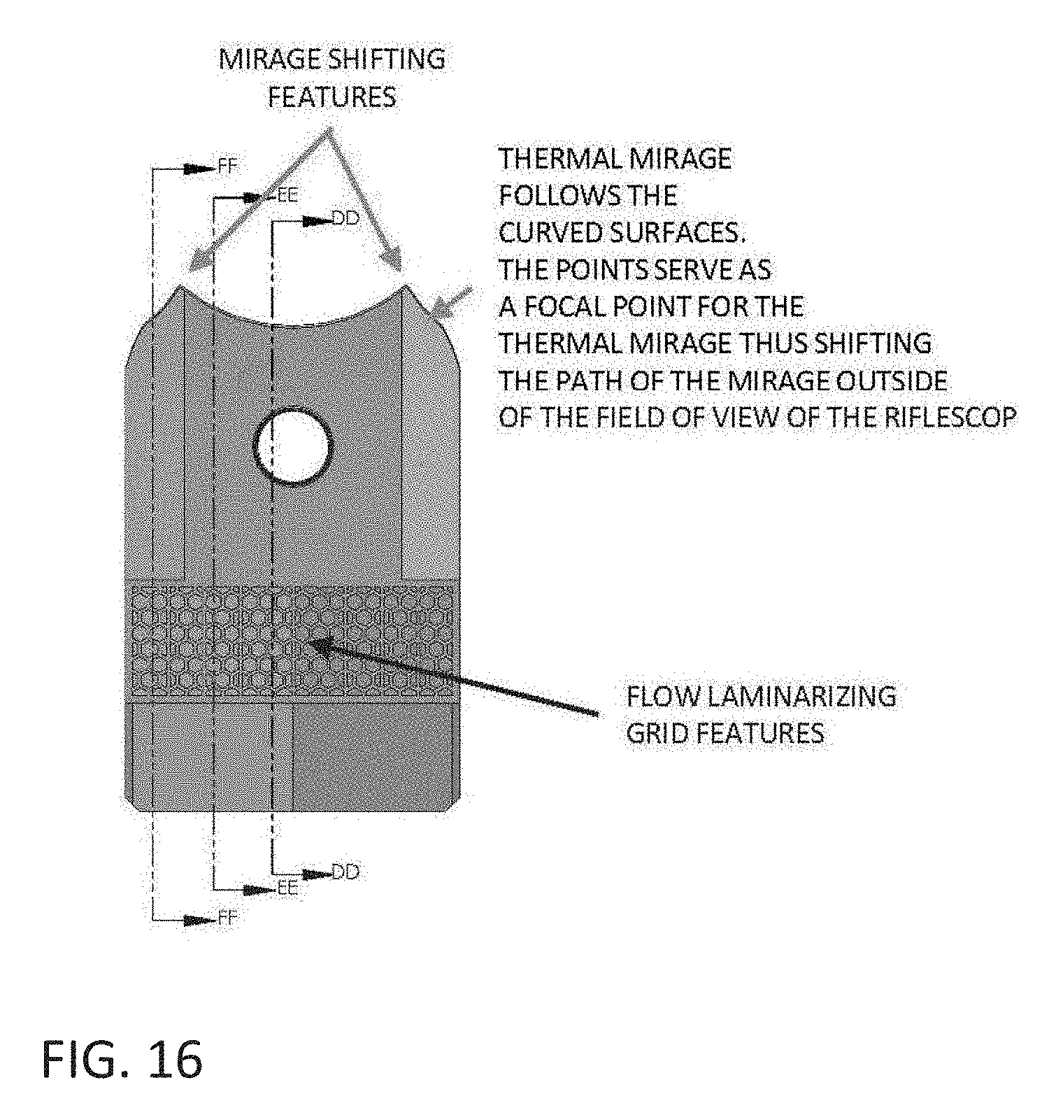
[0026] FIG. 16 is a front view of the device and shows the thermal mirage mitigation feature and the flow laminarizing features.
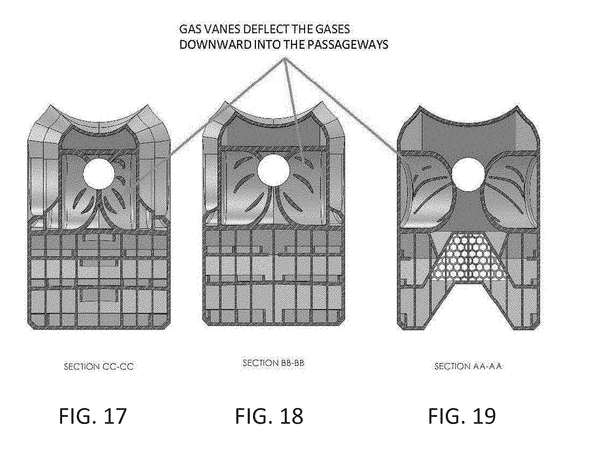
[0027] FIG. 17 is a section view CC-CC showing the deflection vanes in the second chamber.
[0028] FIG. 18 is a section view BB-BB showing the deflection vanes in the third chamber.
[0029] FIG. 19 is a section view AA-AA showing the deflection vanes in the fourth chamber.
[0030] FIG. 20 is a section view DD-DD and shows the muzzle attachment feature, the levels of gas flow, the heat buffer volume and the flow laminarizing features.
[0031] FIG. 21 is a section view EE-EE showing the path of the gas flow through the passageways.
[0032] FIG. 22 is a section view FF-FF showing the path of the gas flow through the passageways and details the swirl inducting fins that are present on various levels.
[0033] FIG. 23 shows the hidden lines visible view from which multiple section views originate.
[0034] FIG. 24 is a section view LL-LL and shows the gas flow path as the gases are diverted downward into the passageways.
[0035] FIG. 25 is a section view RR-RR and show the vanes and diversion features from the level 1 passageways.
[0036] FIG. 26 is a section view of the heat buffer volume onto the separation plate. The separation plate provides a barrier between the diversion chambers and the heat buffer volume.
[0037] FIG. 27 is a section view JJ-JJ and shows the view of the vanes and diversion features at the bullet path elevation.
[0038] FIG. 28 is a section view KK-KK and shows the view of the diversion features/level 1 gas flow passageway floor.
[0039] FIG. 29 is a section view MM-MM and shows the direction of gas flow in level two.
[0040] FIG. 30 is a section view NN-NN and shows the direction of gas flow in level three.
[0041] FIG. 31 is a section view PP-PP and shows the direction of gas flow in level four, looking downward.
[0042] FIG. 32 is a section view PP-PP and shows the direction of gas flow in level four, looking upward.
* * * * *
D00000

D00001

D00002

D00003

D00004

D00005

D00006

D00007

D00008

D00009

D00010

D00011

D00012
D00013
D00014

D00015

D00016

D00017
D00018
D00019

D00020
XML
uspto.report is an independent third-party trademark research tool that is not affiliated, endorsed, or sponsored by the United States Patent and Trademark Office (USPTO) or any other governmental organization. The information provided by uspto.report is based on publicly available data at the time of writing and is intended for informational purposes only.
While we strive to provide accurate and up-to-date information, we do not guarantee the accuracy, completeness, reliability, or suitability of the information displayed on this site. The use of this site is at your own risk. Any reliance you place on such information is therefore strictly at your own risk.
All official trademark data, including owner information, should be verified by visiting the official USPTO website at www.uspto.gov. This site is not intended to replace professional legal advice and should not be used as a substitute for consulting with a legal professional who is knowledgeable about trademark law.