Wall-mounted Refrigerator And Peltier Effect Cooling System
PINET; Claude ; et al.
U.S. patent application number 16/250400 was filed with the patent office on 2019-08-22 for wall-mounted refrigerator and peltier effect cooling system. The applicant listed for this patent is LES ENTREPRISES ZERONEXT INC.. Invention is credited to Christian-Yves COTE, Gregory Allan Thomas HALL, Claude PINET.
| Application Number | 20190257556 16/250400 |
| Document ID | / |
| Family ID | 60991776 |
| Filed Date | 2019-08-22 |


View All Diagrams
| United States Patent Application | 20190257556 |
| Kind Code | A1 |
| PINET; Claude ; et al. | August 22, 2019 |
WALL-MOUNTED REFRIGERATOR AND PELTIER EFFECT COOLING SYSTEM
Abstract
A refrigerator is wall-mounted. The refrigerator has a frame with an insulated compartment supporting a plurality of shelves, a front panel covering the frame and having at least one window for displaying refrigerated articles supported by the shelves, at least one door to access the articles supported by the shelves, a cooling unit, an air recirculation system having a warm air collector for collecting warm air and having a warm air channel for directing air through the cooling unit to provide cooled air, at least one fan, and a cold air channel for directing the cooled air back into the compartment and a mounting for anchoring the refrigerator with respect to a wall. The thermal efficiency of the refrigerator may be enhanced as described herein.
| Inventors: | PINET; Claude; (US) ; COTE; Christian-Yves; (Montreal, CA) ; HALL; Gregory Allan Thomas; (Guelph, CA) | ||||||||||
| Applicant: |
|
||||||||||
|---|---|---|---|---|---|---|---|---|---|---|---|
| Family ID: | 60991776 | ||||||||||
| Appl. No.: | 16/250400 | ||||||||||
| Filed: | January 17, 2019 |
Related U.S. Patent Documents
| Application Number | Filing Date | Patent Number | ||
|---|---|---|---|---|
| PCT/CA2017/050846 | Jul 12, 2017 | |||
| 16250400 | ||||
| 62363768 | Jul 18, 2016 | |||
| Current U.S. Class: | 1/1 |
| Current CPC Class: | A47F 3/0434 20130101; A47F 7/28 20130101; F25D 2700/12 20130101; F25B 21/02 20130101; F25B 2321/023 20130101; A47F 7/283 20130101; A47F 3/001 20130101; F25D 2700/02 20130101; A47F 3/0408 20130101; F25D 17/04 20130101; F25D 23/10 20130101; F25D 25/02 20130101; F25D 2700/14 20130101; A47F 3/0417 20130101; A47B 73/00 20130101; F25D 2317/062 20130101; F25D 2317/0655 20130101; F25D 31/007 20130101 |
| International Class: | F25B 21/02 20060101 F25B021/02; F25D 17/04 20060101 F25D017/04; F25D 23/10 20060101 F25D023/10; F25D 25/02 20060101 F25D025/02; F25D 31/00 20060101 F25D031/00; A47F 3/04 20060101 A47F003/04; A47F 7/28 20060101 A47F007/28 |
Claims
1. A wall-mounted refrigerator comprising: a frame having an insulated compartment comprising a plurality of shelves; a front panel covering said frame and having at least one window for displaying refrigerated articles supported by said shelves; at least one door to access said articles supported by said shelves; a cooling unit; an air recirculation system having a warm air collector for collecting warm air and having a warm air channel for directing air through said cooling unit to provide cooled air, at least one fan, and a cold air channel for directing said cooled air back into said compartment; a mounting for anchoring said refrigerator with respect to a wall; and wherein a thermal efficiency of said refrigerator is enhanced by at least one of: said shelves comprising staggered shelves having a bottle-support surface for supporting sides of horizontally disposed bottles, said shelves extending partly across said compartment leaving a central portion of said compartment free of any shelves so that in use necks of bottles can be nested within said compartment, said warm air collector being located at a central top portion of said compartment and said cold air channel comprising two channels located at the vertical lateral sides of said compartment, said two channels having openings for directing cold air inwardly towards said shelves for cooling bottles on said shelves; said at least one door being mounted at a side of said compartment to access said shelves from a side, said door incorporating an air channel; said window comprising at least two panes having an outer pane forming said front panel beyond said window; and said cooling unit comprising a thermoelectric cooling unit arranged above said compartment within said frame and having a lower cold air heat exchanger and an upper hot air heat exchanger discharging heated air above said refrigerator, said warm air collector being located at a top of said compartment in direct communication with said lower cold air heat exchanger.
2. The refrigerator as defined in claim 1, wherein said staggered shelves have a conformed bottle-support surface for supporting sides of horizontally disposed bottles.
3. The refrigerator as defined in claim 1, wherein said channels located at the vertical lateral sides of said compartment are joined to the rear of said frame.
4. The refrigerator as defined in claim 1, wherein said channel incorporated into said side door is said cold air channel.
5. The refrigerator as defined in claim 4, wherein said openings of said cold air channel allow for more cold air to be released into said insulated compartment from said cold air channel closer to the middle of said cold air channel than closer to the extremities of said cold air channel.
6. The refrigerator as defined in claim 1, wherein said shelves comprise staggered shelves having a conformed bottle-support surface for supporting sides of horizontally disposed bottles, said shelves extending partly across said compartment leaving a central portion of said compartment free of any shelves so that in use necks of bottles can be nested within said compartment, said warm air collector being located at a central top portion of said compartment and said cold air channel comprising two channels located at the vertical lateral sides of said compartment, said two channels having openings for directing cold air inwardly towards said shelves for cooling bottles on said shelves, and said at least one door comprises two side doors mounted at each side of said compartment to access said shelves from each side, said side doors incorporating said two channels.
7. The refrigerator as defined in claim 6, wherein said cooling unit comprises a thermoelectric cooling unit arranged above said compartment within said frame and having a lower cold air heat exchanger and an upper hot air heat exchanger discharging heated air above said refrigerator, said warm air collector being located at a top of said compartment in direct communication with said lower cold air heat exchanger, and said two channels having, at their top, a channel coupling to said lower cold air heat exchanger cooled air output.
8. The refrigerator as defined in claim 7, wherein said thermoelectric cooling unit comprises: a thermoelectric element having a lower cold side and an upper hot side; a heat sink coupled to said upper hot side, said heat sink including a sealed chamber with a working fluid for dissipating heat generated from said hot side of the thermoelectric element to heat discharge fins disposed above said upper hot side; an ambient air duct and fan arranged to blow ambient air across said heat discharge fins; a cooling plate shaped into at least one truncated pyramid coupled at a pyramid top side to said lower cold side of said thermoelectric element; and cooling fins extending downwardly from said cooling plate at a pyramid base bottom side.
9. The refrigerator as defined in claim 8, wherein said thermoelectric cooling unit comprises between 3 and 7 of said thermoelectric elements each associated with a corresponding said heat sink and said truncated pyramid.
10. The refrigerator as defined in claim 1, wherein said window comprises a dual or triple pane window having an outer pane forming said front panel beyond said window.
11. The refrigerator as defined in claim 10, wherein said window is a triple pane single window with low emissivity glass, having a space between panes filled with an inert gas.
12. The refrigerator as defined in claim 11, wherein said gas is composed of one of krypton, argon and a combination thereof.
13. The refrigerator as defined in claim 1, further comprising a light source in said compartment for illuminating articles supported by said shelves.
14. The refrigerator as defined in claim 13, further comprising a sensor for detecting presence of a person in front of said refrigerator to control a switch to turn on said light source.
15. The refrigeration as defined in claim 14, wherein said sensor for detecting presence of a person is a microwave sensor.
16. The refrigerator as defined in claim 1, further comprising an insolation sensor for detecting an intensity of light incident into said compartment and a user warning and/or event logging module responsive to said insolation sensor.
17. The refrigerator as defined in claim 1, further comprising an interior temperature sensor for detecting a temperature in said compartment and a user warning and/or event logging module responsive to said interior sensor for providing information about a temperature of said compartment over time.
18. The refrigerator as defined in claim 17, further comprising an exterior temperature sensor for detecting an ambient temperature, wherein said user warning and/or event logging module is further responsive to said exterior temperature sensor to provide an indication as to a cause for failure to maintain a temperature of said compartment due to an unacceptable rise in ambient temperature.
19. The refrigerator as defined in claim 1, further comprising a sheet neighboring at least a part of said cooling unit and configured to prevent water condensed due to said cooling unit's cooling effect from accumulating in said insulated compartment.
20. The refrigerator as defined in claim 19, wherein said sheet is a geotextile material.
Description
[0001] The present application claims priority of the U.S. provisional application 62/363,768 filed on Jul. 18, 2016.
TECHNICAL FIELD
[0002] The present application relates to wall-mounted and/or floor-mounted refrigerators, mounting supports and installation supports thereof, and Peltier effect cooling systems.
BACKGROUND
[0003] Many traditional refrigerated wine cellars often store wine bottles with the cork or the base facing outward, in some cases with each bottle hidden in a hollow casing, only revealing the outwardly protruding head or base, each bottle layered one on top of the other and/or one side by side. However, this arrangement does not allow a consumer to view the labels of the bottles without pulling out each bottle. This arrangement makes it therefore more difficult to locate a desired name, vintage, blend or batch.
[0004] Furthermore, refrigeration units, such as those used to regulate a wine refrigeration or temperature regulation unit, may be cumbersome and clunky due to their large size. This large size may be attributed to, for example, the cooling units found within the refrigerator, where a large compressor for compression refrigeration is a cooling system often used to achieve the desired lowering in temperature. Moreover, the refrigerant used in the compression refrigeration system, once heated as it undergoes a phase change (evaporates: from liquid to gas) requires that it be cooled down (condense: from gas back to liquid) so it may repeat the refrigeration cycle, also requires more space, as the heat is often dissipated outside of the refrigerator.
[0005] Registered Community Design number 002552570-0001 registered on 7 Oct. 2014 by OHIM shows a wine refrigerator in which bottles are stored on two columns of shelves with the bottles arranged horizontally on the shelves to have their cork ends staggered and nested. The storage of bottles is only one bottle width deep and less than two bottle lengths wide. Such a refrigerator offers the advantage of displaying bottle labels through a front window, and of being of small footprint. A pleasant presentation of wine bottles can be provided in a home or commercial dining room. However, such a refrigerator has the design disadvantage that the surface area of the refrigerated compartment to total volume is larger than for the above-described wine refrigerators which are at least bottle-height deep and more cubic in dimensions. It also has the disadvantage that little room is left for a traditional refrigeration compressor.
[0006] The present invention addresses the problems described above.
SUMMARY
[0007] One of the less bulky options of cooling systems for a refrigerator, such as a wine refrigeration unit, is a Peltier effect cooling system. This cooling system is far less cumbersome and bulky, as it does not function using compression refrigeration or require the cooling of a large quantity of refrigerant. Instead, the Peltier cooling system functions using a thermoelectric element composed of two semi-conductors forming p-n junctions. One of these semi-conductors may be p-doped while the other may be n-doped. Once an electric current passes through the thermoelectric element, one side of the thermoelectric element cools off while the other heats up. The cold side of the thermoelectric element is used to cool off a given system where heat accumulating on the hot side of the thermoelectric element is dissipated using, for example, a heat sink, where the heat is evacuated. However, the Peltier effect cooling system has certain limitations, such as those resulting from the small size and properties of the thermoelectric element, thus posing a challenge when the system is to cool or maintain the temperature of, for example, a large volume of air found in, for example, a large compartment.
[0008] Applicant has discovered that a truncated pyramid-shaped cooling plate may be used to enhance the cooling power of the thermoelectric element by increasing the heat transfer between the cooling plate and the cold side of the thermoelectric element while acting as a divide and improving the insulation between the refrigerated compartment and the portion of the refrigerator circulating the warmed or warmer air.
[0009] Applicant has also found that a convection system may be used to effectively circulate cooled air through a refrigerated compartment, where the cooled air circulates through channels incorporated into the refrigerator's side doors, these channels possessing openings for allowing the cooled air to be distributed along the length of the refrigerated compartment, while reducing mixing between the warm and cooled air.
[0010] In accordance with one broad aspect of some embodiments, there is provided a wall-mounted refrigerator having a frame with an insulated compartment comprising a plurality of shelves, a front panel covering the frame and having at least one window for displaying refrigerated articles supported by the shelves. The refrigerator also has at least one door to access the articles supported by the shelves and a cooling unit. Furthermore, the refrigerator has an air recirculation system having a warm air collector for collecting warm air and having a warm air channel for directing air through the cooling unit to provide cooled air, at least one fan, and a cold air channel for directing the cooled air back into the compartment. The openings of the cold air channel may allow for more cold air to be released into the insulated compartment near the middle of the cold air channel than towards the extremities of the cold air channel. The refrigerator also has a mounting for anchoring the refrigerator with respect to a wall. The thermal efficiency of the refrigerator is enhanced by at least one of the following. First, the shelves have staggered shelves with a conformed bottle-support surface for supporting sides of horizontally disposed bottles, where the shelves extend partly across the compartment leaving a central portion of the compartment free of any shelves so that in use necks of bottles can be nested within the compartment. The warm air collector is located at a central top portion of the compartment and the cold air channel with two channels is located at the vertical lateral sides of the compartment. The two channels have openings for directing cold air inwardly towards the shelves for cooling bottles on the shelves. Second, the at least one door is mounted at a side of the compartment to access the shelves from a side, the door incorporating an air channel. Third, the window with a dual or triple pane window has an outer pane forming the front panel beyond the window. Fourth, the cooling unit has a thermoelectric cooling unit arranged above the compartment within the frame and has a lower cold air heat exchanger and an upper hot air heat exchanger discharging heated air above the refrigerator, the warm air collector being located at a top of the compartment in direct communication with the lower cold air heat exchanger.
[0011] Another broad aspect of some embodiments is a refrigerator where the cooling is performed by a cooling liquid or refrigerant, such as water, where the heat dissipation from the cooling liquid or refrigerant is conducted by an external cooling system, located outside of the refrigerator. The cooling liquid absorbs the heat from the warmed air and dissipates the heat externally. In some embodiments, the external cooling system may have a compressor and/or a condenser.
[0012] The window of the refrigerator may be a dual or triple pane window. The number of panes may also be superior to three. There may also be an outer pane forming the front panel beyond the window. The window may be a triple pane single window with low emissivity glass. There may be a space between panes filled with an inert gas. The gas may be composed of one of krypton, argon or a combination thereof.
[0013] The refrigerator may also have a light source in the refrigerator's compartment for illuminating articles supported by the refrigerator's shelves in the compartment. The refrigerator may also have a sensor for detecting the presence of a person in front of the refrigerator to control a switch to turn on the light source. The sensor for detecting the presence of a person may be a microwave sensor.
[0014] The refrigerator may also have a fault detection device. As such, the refrigerator may have an insolation sensor for detecting an intensity of light incident into the refrigerator's compartment and a user warning and/or event logging module responsive to the insolation sensor. The refrigerator may also have an interior temperature sensor for detecting a temperature in the compartment and a user warning and/or event logging module responsive to the interior sensor for providing information about a temperature of the compartment over time. Moreover, the refrigerator may have an exterior temperature sensor for detecting an ambient temperature. The user warning and/or event logging module is further responsive to the exterior temperature sensor to provide an indication as to a cause for failure to maintain a temperature of the compartment due to an unacceptable rise in ambient temperature.
[0015] In some embodiments, the refrigerator may have a sheet neighboring at least a part of the cooling unit and configured to prevent water condensed due to the cooling unit's cooling effect from accumulating in the insulated compartment. The sheet may be a geotextile material.
[0016] Another broad aspect of some embodiments is a floor-mounted refrigerator. The floor-mounted refrigerator is anchored to the floor using an anchoring foot. The floor-mounted refrigerator may have at least one window display located on at least one face of the refrigerator. The refrigerator may have at least two window displays, where at least one of the at least two window displays is located on either face of the refrigerator.
[0017] Another broad aspect of some embodiments is a thermoelectric cooling unit which has a thermoelectric element with a lower cold side and an upper hot side. The cooling unit also has a heat sink coupled to the upper hot side, the heat sink including a sealed chamber with a working fluid for dissipating heat generated from the hot side of the thermoelectric element to heat discharge fins disposed above the upper hot side. Furthermore, the cooling unit includes an ambient air duct and fan arranged to blow ambient air across the heat discharge fins. Also, the cooling unit has a cooling plate shaped into at least one truncated pyramid coupled at a pyramid top side to the lower cold side of the thermoelectric element. Moreover, the cooling unit has cooling fins extending downwardly from the cooling plate at a pyramid base bottom side.
[0018] The cooling unit may have between three to seven thermoelectric elements, where each of these elements is associated with a heat sink and a truncated pyramid of a cooling plate.
[0019] Another broad aspect of some embodiments is a support device for a wall-mounted refrigerator. The support device has track brackets mounted to a wall for receiving a set of guides incorporated to the rear of the wall-mounted refrigerator. Once the guides are slid into the track brackets, the track brackets prevent movement of the refrigerator along two of three of axes x, y and z, wherein the refrigerator may still move vertically along the wall. The support device also has pedestal support with an adjustable height for receiving the vertical weight of the refrigerator. The pedestal support may have a cavity for receiving a cable of the refrigerator.
[0020] Another broad aspect of some embodiments is a lateral door of a refrigerator running along the length of the refrigerated compartment refrigerator. The lateral door has a channel for passing air cooled by a cooling unit of the refrigerator and for coupling to a channel of the cooling unit. The lateral door's channel has openings for distributing air along the length the refrigerated compartment. The air distributed in this channel may be cooled air. Alternatively, the air distributed in this channel may be warmed air.
[0021] Another broad aspect of some embodiments is a temporary installation device for a wall-mounted refrigerator. The temporary installation device has two feet, each foot having a receiving means for receiving a lateral portion of the refrigerator's base and stabilizing the vertically-positioned refrigerator. The feet also have a rail for receiving the refrigerator and for allowing the refrigerator to glide along the rail for positioning of the refrigerator.
BRIEF DESCRIPTION OF DRAWINGS
[0022] The invention will be better understood by way of the following detailed description of embodiments of the invention with reference to the appended drawings, in which:
[0023] FIG. 1 is an oblique view of a wall-mounted or floor-mounted refrigerator having a shallow depth and one or more display windows for displaying cooled items.
[0024] FIG. 2 is a side oblique view of the upper part of a wall-mounted or floor-mounted refrigerator have a shallow depth and one or more display windows for displaying cooled items.
[0025] FIG. 3A is a flowchart diagram of a set of steps of an exemplary flow of air in a wall-mounted or floor mounted refrigerator.
[0026] FIG. 3B is a flowchart diagram of an exemplary set of steps of an alternative exemplary flow of air in a wall-mounted or floor mounted refrigerator.
[0027] FIG. 4A is a front view of an exemplary Peltier effect thermoelectric cooling device.
[0028] FIG. 4B is as side view of an exemplary Peltier effect thermoelectric cooling device.
[0029] FIG. 5 is a top-down view of an exemplary cooling plate of a Peltier effect thermoelectric cooling system.
[0030] FIG. 6A is a side-oblique view of an exemplary display of a wall-mounted or floor-mounted refrigerator.
[0031] FIG. 6B is an oblique back view of an exemplary display of a wall-mounted or floor-mounted refrigerator.
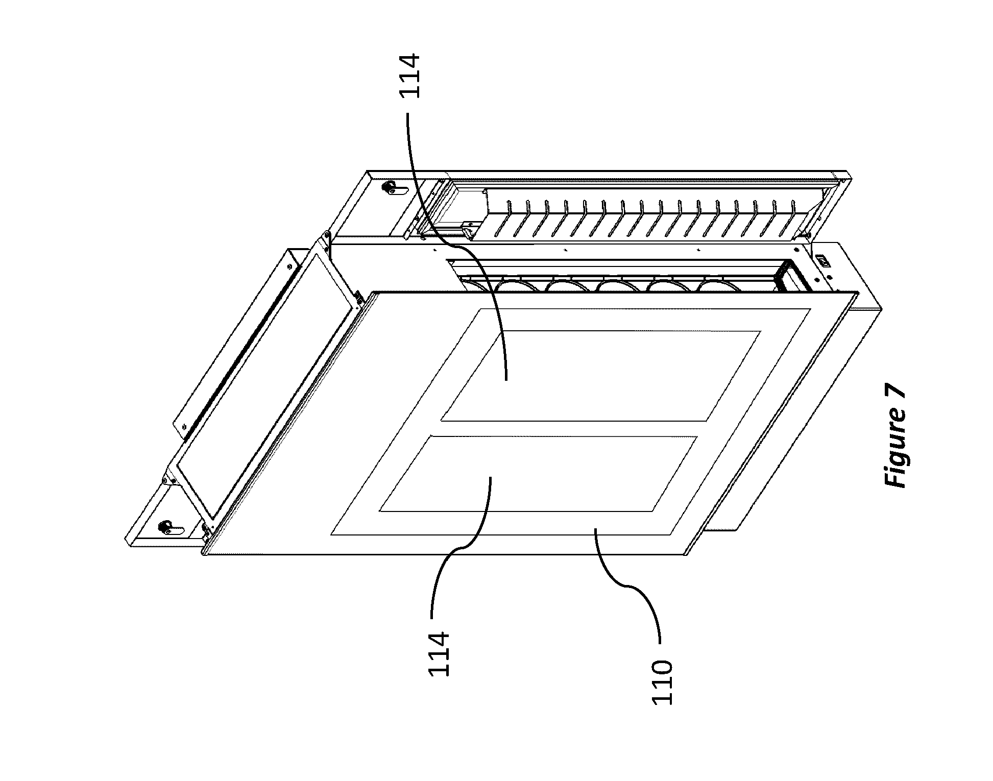
[0032] FIG. 7 is an oblique view of another exemplary display of a wall-mounted or floor-mounted refrigerator.
[0033] FIG. 8A is a side view of an exemplary plurality of shelves of an exemplary refrigerator.
[0034] FIG. 8B is a front view of an exemplary plurality of shelves of an exemplary refrigerator.
[0035] FIG. 9 is a schematic block diagram of an exemplary fault detection system of an exemplary refrigerator.
[0036] FIG. 10 is an oblique view of exemplary installation supports used to install an exemplary wall-mounted or floor-mounted refrigerator.
[0037] FIG. 11 is an oblique bottom-back view of an exemplary refrigerator.
[0038] FIG. 12 is a side cross-sectional view of an exemplary Peltier effect thermoelectric cooling device.
[0039] FIG. 13 is a front-side perspective view of a portion of an exemplary refrigerator with an exemplary air channel having openings that are not equally spaced apart.
DETAILED DESCRIPTION
[0040] A first aspect of the present embodiment relates to a wall-mounted or floor mounted refrigerator having a shallow depth and one or more display windows for displaying cooled items. The appearance of such a refrigerator is known from Registered Community Design number 002552570-0001 registered on Jul. 10, 2014 by OHIM. In a preferred embodiment, the refrigerator is a refrigerated wine cellar, but may also be a refrigeration unit for any kind of bottled or canned beverages, such as, for example, soft-drinks, sparkling wine and beer, or desserts, such as fruit, slices of pies, etc.
[0041] Reference is now made to the drawings. FIG. 1 is an exemplary embodiment of a wall-mounted or floor-mounted refrigerator 100. The refrigerator 100 includes a display area 110 for showing the contents of the refrigerator 100 on a first panel of the refrigerator 100. The display area 110 may comprise a full transparent window. In some embodiments, only portions of the display area 110 may be transparent, for example, where these portions are for showing labels of bottles cooled in the refrigerator 100. This can help improve insulation of the refrigerator since the non-window portions of the area 110 can provide for better insulating. The display area 110 may be made of, for example, glass or acrylic. In an alternative embodiment, where the refrigerator is mounted to the floor on, for example, a large pedestal to prevent the refrigerator from collapsing either forwards or backwards, the refrigerator may have a dual display window, one display window on either face or panel of the refrigerator where the refrigerated items are visible from either side of the refrigerator, such as from the front and the back.
[0042] The refrigerator 100 also comprises a cooling unit 140. In a preferred embodiment, the cooling unit 140 is located at the top of the refrigerator 100 to help with exhausting warm air, although the cooling unit 140 can be arranged at other locations within the refrigerator 100. The cooling unit 140 may be a Peltier effect cooling apparatus as further described below, a conventional compressor-based refrigeration unit, or a replaceable latent heat storage module.
[0043] The refrigerator 100 also comprises one or two side doors 120 on either side of the refrigerator 100. In FIG. 1, these side doors 120 are shown open. In a preferred embodiment, the side doors 120 open laterally away from the refrigerator 100 towards the rear of the refrigerator 100, using, for example, a hinge mechanism. Alternatively, in other embodiments, the side doors 120 may open in other ways such as by sliding open, using, for example, a set of rails. The side doors 120 can each comprise a cold air channel 130 for passing cold air and distributing the cold air along the length of the refrigerator 100 through openings found along the channel 130. In a preferred embodiment, these openings are vents. In other embodiments, the openings can be, for example, perforations, small holes or a grid. At an open top portion of the channel 130, when the door 120 is closed, a cold air channel 132 from cooling unit 140 is coupled. In the arrangement of FIG. 2, this cold air coupling is done from a top of the channel 130, however, it could also be a coupling from a side port into a top of channel 130. Gasket seals are optional for this coupling. However, the gasket seals may improve coupling efficiency.
[0044] The depth 150 of the refrigerator 100 may be inferior to the width 151 of the refrigerator 100. The width 151 may be sufficiently large to contain bottled wine, for example when the bottles are lying on one side, where the head and the base of each bottle point either towards or away from each of the doors 120. In this example, the side doors 120 may be slender in order to match the depth 150 of the refrigerator 100. The slender side doors 120 allow for minimal cooled air to mix with the warmer ambient air when a side door 120 is opened in order to, for example, remove or add a refrigerated item.
[0045] Reference is now made to FIG. 2. FIG. 2 shows a close-up of an exemplary side door 120 that is opened laterally. Each of side doors 120 may have a cold air channel 130 for channeling the air cooled by the cooling unit 140. Each of the channels 130 may have a series of openings 135 along the channel 130 for passing the cooled air as described above. The cooled air may be distributed along the channel 130 through the openings 135 in order to cool the entirety of the refrigerated space containing the refrigerator items. FIG. 2 also shows a plurality of shelves 136 which are used to support the refrigerated items, such as bottled wine. The plurality of shelves 136 also create a channel, guiding the cooled air to a central opening 137 as the air gradually warms. The central opening 137 may be formed by the plurality of shelves 136, located between two pluralities of shelves 136 (which may also be described as the two shelve racks 136), as shown in FIG. 2. The central opening 137 may be a space allowing the warmed air to rise back up by convection to the cooling system 140 for cooling. This air circulation system, where the cool air descends in the channels and then rises at the central opening 137 of the refrigerator 100, reduces the mixing of the warmed air with the cooled air by separating both and increases the efficiency of the cooling process. In an alternative embodiment, the refrigerator 100 may optionally not have a central opening 137 where, for example, the plurality of shelves is not divided in two in the middle but forms instead one continuous rack of shelves. In this exemplary embodiment, the hot air may instead rise, for example, at the front and/or the back of the compartment of the refrigerator 100, where the refrigerator 100 is configured in such a way as to limit the mixing of the cooled and warm air (such as through the use of channels 130). In another alternative embodiment, the lateral cold air channels 130 may not be incorporated to the side doors 120 but are joined to, for example, the rear of the refrigerator, the channels 130 placed in such a way as not to hinder access to the refrigerated items when the side doors of the refrigerator are opened.
[0046] Reference is now made to FIG. 13, illustrating an exemplary channel 130 of a refrigerator 100 having openings 135 that are not equally spaced apart. In some embodiments, the pathway taken by the air in the refrigerator 100 as it transitions from cold to warm, and warm to cold, may leave certain of the items stored in the refrigerator 100 to be warmer than others depending on their position in the storage compartment of the refrigerator 100. In order to compensate for this temperature difference of the refrigerated items, the amount of cold air released through the openings 135 may vary as a function of where it has been observed that the refrigerated items may be warmer (e.g. more cold air released where items tend to be warmer, and less cold air where the items tend to be cooler). The amount of cold air released may be controlled, for instance, by varying the spacing of the openings 135 as shown in FIG. 13, where less space or separation between the openings leads to a greater concentration of openings in a given area and the release of more cold air from the channel 130. The amount of cold air released may also be controlled by, for example, varying the width of the openings 135 (e.g. a larger opening releases more cold air), where larger openings are present where the items tend to get warmer. For example, it has been discovered that, in some examples, refrigerated items stored in the middle of the refrigerator 100 tend to be warmer than those stored at either the top or bottom of the refrigerator 100. In these examples, an air channel 130 where the openings 135 allow for a greater release of cold air towards the middle (e.g. the openings 135 are less separated towards the middle of the channel), and less at the vertical extremities of the channel 130, may compensate and balance the temperature differential that may be observed between the refrigerated items positioned at different locations in the refrigerator 100.
[0047] The refrigerator 100 may also have air filters to prevent the accumulation of particulates on different components of the refrigerator 100, such as the cooling fins 143 and heat dissipation fins. The air filters may provide a barrier at different air passage ways, such as positioned somewhere along the air intake located at the back of the refrigerator 100 for taking in ambient air, at the ambient air import before the ambient air is fanned through the heat dissipating fins, and/or between the refrigeration compartment and the cooling unit 140, such as with the positioning of air filter 137.
[0048] Reference is made to FIG. 11, illustrating the bottom-back portion of an exemplary refrigerator 100. The air intake may be located at the back of the refrigerator 100, where the air may enter from the bottom-back of the refrigerator 100, such as through openings 125 and flow up through the channel 176. The back of the refrigerator 100 may also have an opening for providing a cable to be connected to a power source, such as the opening 124.
[0049] In an alternative embodiment, the cooling of the warmed air of the refrigerator may be performed by a cooling liquid or refrigerant, such as water, where the heat dissipation from the cooling liquid or refrigerant may be conducted by an external cooling system, the heat sink located outside of the refrigerator. In this embodiment, the cooling liquid absorbs the heat from the warmed air and dissipates the heat externally. There may be a channel, such as a tube or cable, running between the refrigerator and the cooling system for carrying the warmed cooling liquid or refrigerant to the cooling system and returning the now cooled liquid or refrigerant back to the refrigerator. In some embodiments, but not limited to these, when the cooling is performed by compression refrigeration, the refrigerant may undergo phase shifts as it absorbs (from liquid to gas) and then dissipates (from gas back to liquid) the heat. The cooling system may have a compressor for compressing the heated gas into, for example, a superheated vapor. The cooling system may also include a condenser for condensing the superheated vapor or heated gas back into a liquid. In such examples, the condenser may include a coil for passing the superheated vapor or heated gas and running, for example, cold water on the coils for dissipating the heat. Such a cooling unit may be compacted into a small casing. In some examples, where the cooling system is connected to a power source, the refrigerator may not be connected to a power source.
[0050] FIG. 3A is a flowchart of an exemplary set of steps 300a depicting the flow of air to cool a refrigerator 100, where the refrigerator 100 may have two sets of plurality of shelves for carrying refrigerated items, the two pluralities of shelves forming the central opening between the plurality of shelves running along the central axis of the refrigerator 100. Ambient air can first enter the refrigerator 100 through an opening located at the back of the refrigerator 100. For instance, this opening may be at or near the bottom of the refrigerator 100 as shown in FIG. 11. This opening may be, for example, a channel (such as channel 176 as shown on FIG. 6B) that allows the ambient air to travel up the back of the refrigerator and enter the cooling unit 140 at step 320. The air is then cooled by the cooling unit 140 at step 330a which may be, for example, a Peltier effect cooling apparatus. The cooled air is then pushed to both sides of the refrigerator at step 340a and then funneled down the sides of the refrigerator 100 through, for example, channels incorporated or attached to the refrigerator's side doors at step 350a. The cooled air is distributed along the length of the channels 135, and as the air is distributed, it may travel over a plurality of shelves 136 used to carry refrigerated items, such as wine bottles. In an example where these pluralities of shelves 136 are perpendicular to the side doors 120 of the refrigerator 100, the plurality of shelves 136 form a series of channels for directing the air towards the center opening found between the plurality of shelves 136. When the refrigerated items are bottles, the bottles further form with the shelves of the plurality of shelves 136 tight spaces in which the air is pushed through. The cooled air, now warmed, moving and directed by the shelves to the center opening between the plurality of shelves 136, now rises up this central opening at step 360a as hot air rises as a result of convection. Once the warm air reaches the top of the refrigerator 100, it is distributed along the length of the cooling unit 140 located as the top of the refrigerator 100 and passes through the cooling unit 140 for re-cooling at step 360a. The steps 330a-370a may then be repeated, as the air is recycled and cooled once more.
[0051] In an alternative embodiment of another exemplary set of steps 300b depicting the flow of air to cool a refrigerator 100 as shown in FIG. 3B, once air is cooled by the cooling unit 140 at step 330b, the cooled air may be pushed down through a central portion of the refrigerator 100 at step 340b, where the cooled air is channeled across the plurality of shelves 136 and the refrigerated items, such as the bottles resting on the shelves 136 in the refrigerator 100 at step 350b. The warmed air is then returned through the side doors 120 of the refrigerator 100 at step 360b, and rises back up as a result of convection through, for example, the channels 130 incorporated into the side doors 120. The warm air passes through the cooling unit 140 for re-cooling at step 370b and steps 330b-370b may then be repeated as the air is recycled and cooled once more.
[0052] Reference is now made to FIG. 12, showing an exemplary Peltier effect thermoelectric cooling apparatus that is part of an exemplary refrigerator. As shown in FIG. 12, some embodiments of the refrigerator may have a barrier, film or flexible sheet surrounding at least a portion of the Peltier effect thermoelectric cooling apparatus to prevent or dissipate water or moisture build up resulting from the Peltier effect thermoelectric cooling apparatus as the air is cooled. In some instances, the sheet 126 may be a geotextile cloth 126, preventing the accumulated water from entering the display/storage compartment of the refrigerator. In some embodiments, the sheet 126 may be a form of absorbent material that removes and/or eliminates the water as produced. The refrigerator may be configured to allow for easy replacement of the sheet 126 over time.
[0053] A second aspect of the invention is a Peltier effect thermoelectric cooling apparatus. Reference is now made to FIGS. 4A and 4B showing an exemplary Peltier effect cooling apparatus 200. The Peltier effect cooling apparatus 200 has a thermoelectric element 146. The thermoelectric element 146 may be composed of two semi-conductors forming a p-n junction. The semi-conductors may be composed, for example, of doped bismuth chalcogenides (Be.sub.2Te.sub.3 or Be.sub.2Se.sub.3). When an electric current travels through the thermoelectric element 146, one side of the thermoelectric element 146 is heated while the other is cooled. The efficiency of the thermoelectric element is affected namely by the difference between the temperature of the refrigerator and that of the room. In such embodiments, a temperature differential of about 10 degrees Celsius may be achieved while maintaining the efficiency of the thermoelectric element. The cooled surface may be used in refrigeration, by, for example, cooling the nearby air. In one embodiment, the thermoelectric element 146 may be a series of thermoelectric chips, such as those used to cool computer components. In a preferred embodiment, there may be five evenly spaced thermoelectric chips for cooling a space equivalent to a volume of around 110 liters or 3.8 cubic feet. However, depending on the size of the compartment of the refrigerator that is required to be cooled, different embodiments may comprise less (e.g. 3) thermoelectric chips or more. Achieving a greater temperature differential between the temperature of the refrigerator and that of the room may also require a greater number of thermoelectric chips, elements, surface area or efficiency of said elements as the power output of the thermoelectric elements drops as the desired temperature differential increases (the power (W) of the thermoelectric elements is inversely correlated to the desired temperature differential between the room and that of the refrigerator).
[0054] In another embodiment, the thermoelectric element 146 may be one continuous element instead of a plurality of thermoelectric chips.
[0055] The thermoelectric cooling apparatus 200 also has a heat sink 148 for trapping and dissipating excess heat produced by the hot side of the thermoelectric element 146. The thermoelectric element 146 may be coupled to the heat sink 148. The heat sink 148 may comprise tubes 142 or a sealed chamber containing a refrigerant. In one example, the refrigerant may be a Freon gas. The refrigerant absorbs the heat of the hot side of the thermoelectric plate 146, evaporates and rises up the tubes 142. The heat sink 148 may also include a fan system 141. The fan system 141, such as a refrigerator air duct fan, directs air to heat discharge fins in contact with the tubes 142 where the air is at ambient or slightly above ambient temperature, cooling off the heated tubes 142 and the evaporated refrigerant contained within. Heat is thus transferred from the refrigerant to the ambient air, the now warmer ambient air evacuated from the Peltier cooling device 200. The refrigerator air duct and fan 141 are arranged to blow air from a refrigerator interior compartment warm air port across the cooling fins to a cold air port. As the refrigerant is cooled down, it undergoes another phase shift, condensing as it is cooled, the liquid refrigerant trickling down inside the tube 142 and, now cooled, may then absorb more heat from the hot side of the thermoelectric element 146 and repeat the process. The person having ordinary skill in the air will readily recognize that other forms of heat sinks may be used, where, for example, the heat sink does not use a refrigerant but simply heat discharge fins and a fan.
[0056] In an alternative embodiment, a heat conductive plate similar to the cooling plate 144 may be joined, directly or indirectly, to the hot side of the thermoelectric element 146, adapted, for example, to the small size of the thermoelectric element 146, allowing for a better heat transfer to the heat discharge fins and fans. In some embodiments, this heat conductive plate may be used instead of the heat sink 148.
[0057] The Peltier cooling apparatus 200 may also have cooling fins 143 on the cold side. The fins 143 may be grouped in sets of fins 149. In one embodiment, these sets of fins 149 may be evenly spaced. In another embodiment, these sets of fins 149 may be irregularly spaced or not spaced, consisting of one uniform body of fins 143 evenly interspersed throughout. In one example, the sets of fins 149 may be placed in a symmetrical arrangement. In another embodiment, there may be one single set of fins 149 running along the whole of the Peltier cooling apparatus 200. In a preferred embodiment, the number of sets of fins 149 is equal to the number of thermoelectric elements 146, where each of the set of fins 149 may be aligned with the thermoelectric element 146.
[0058] In order to increase the efficiency of the cooling process by increasing the air exposed to a cold surface area, the Peltier cooling apparatus 200 may include a metal plate 145 that may be joined, directly or indirectly, to the thermoelectric element 146. Such a metal plate 146 may be made out of aluminum or any other heat conducting metal, such as copper. The Peltier cooling device 200 may also include a cooling plate 144 with a truncated pyramidal shape joined to the thermoelectric element 146 and to the set of fins 149. This cooling plate 144 may be made out of a good heat conductor, such as, for example, aluminium or copper. The cooling plate 144 increases the cooling effect by increasing the surface area of the cold surface and the amount of air coming into contact with the cold surface. The pyramid shape of the cooling shape 144 is truncated so as to allow at least one thermoelectric element 146 to rest on its top surface, the truncated face. In the example where the thermoelectric element 146 is a plurality of thermoelectric chips, these chips may have a small surface area (e.g. not more than a few square centimeters). Thus, when the thermoelectric element 146 is joined to the cooling plate 144, the cold side of the thermoelectric element 146 in turn cools down the cooling plate 144. The cooling plate 144 increases the cooling power of the thermoelectric element 146 by increasing the heat transfer between the cooling plate 144 and the cold side of the thermoelectric element 146 by increasing the surface area of the cold surface for better heat transference from the warmed air. The cooling plate 144 distances the cooled surfaces from the hot side of the thermoelectric element 146 in order to minimize undesired heat transfer between the refrigerated compartment, the cooled air and the portion of the refrigerator 100 involved in dissipating heat (including, for example, the hot side of the thermoelectric element 146 and the heat sink 148)
[0059] In an exemplary embodiment of the cooling plate 144 as shown in FIG. 5, the cooling plate 144 is shaped with a plurality of pyramid shapes 147, the top of each pyramid shape 147 dimensioned to receive one thermoelectric element 146 (such as a thermoelectric chip). In one example, the top of the pyramid shape 147 may match that of the thermoelectric element 146. In another example, the top of the pyramid shape may still receive the thermoelectric element 146 while not matching its dimensions. In a preferred embodiment, there are five pyramid shapes 147, each for receiving one of five thermoelectric chips. It will be understood that the number of pyramid shapes 147 may vary, depending on the number of thermoelectric elements 146. The number of pyramid shapes 147 may match the number of thermoelectric elements 146 or may be different (e.g. such as where there are two thermoelectric chips 146 per pyramid shape). In an alternative embodiment, the entire cooling plate 144 may be shaped into one single plate, where the flattened top of the truncated pyramid is shaped to receive one single thermoelectric element 146. The walls of the pyramid shape 147 are depicted as a staircase, where the pyramid shape 147 is a truncated Mayan pyramid. The walls of the pyramid shape 147 may, in an alternative embodiment, be smooth, such as a truncated Egyptian pyramid.
[0060] In an alternative embodiment, a heat sink, similar to the heat sink 148, may be used to gather the heat from the warmed air rising from the refrigerator's compartment and dissipate it through the thermoelectric element 146. In this alternative embodiment, the heat sink is coupled to the cold side of the thermoelectric element 146 and may include a sealed chamber, such as a set of tubes or a heat pipe, filled with a working fluid or refrigerant as understood by a person skilled in the art to work for small temperature differentials. The working fluid would receive the heat transferred from the warmed air, evaporate, transfer the heat to the cold side of the thermoelectric element 146, condense then flow back down to repeat the process. The heat sink would also have cooling fins for cooling the warmed air. The heat sink would include a fan for blowing the warmed air across the cooling fins to a cooled air port to be recirculated in the refrigerated compartment.
[0061] A third aspect of the present invention is that of a display for a refrigerator 100 located on one of the refrigerator's panels. Reference is now made to FIG. 6A showing an exemplary embodiment of a display area 110 or window of a refrigerator 100, placed behind an outer pane forming the panel. The display area 110 may include an outer layer 111 and an inner layer 112. The outer layer 111 may be of a different dimension than the inner layer 112. The display 110 may be a low emissivity glass panel, where one or more surfaces of the outer and/or inner layer may be coated with a transparent metal layer. The inner layer 112 may be further composed of two or more sub-layers. In a preferred embodiment, there are two sub-layers. There may be a space 115 formed between the outer layer 111 and the inner layer 112. The space 115 may be filled with an inert gas such as Argon or Krypton. There may also be a space formed between the sub-layers. The space between the two sub-layers may be filled with an inert gas, where the inert gas may be, for example, Argon or Krypton. The inner layer 111 and outer layer 112 may be made of a transparent substance such as glass or a polycarbonate. In some embodiments, the display may be triple glazed argon-filled window (or krypton filled) with the outer glass pane being larger than the two inner panes, so that the outer pane forms the outer surface of the refrigerator 100, while the inner panes are for the display window. A suitable masking on a surface of the outer pane provides the finished appearance for the refrigerator surrounding the display window 110. In this masked area, opaque insulation can be used. In an alternative embodiment, the display may be a double-glazed argon-filled (or krypton-filled), or filled with another inert gas, window.
[0062] A fourth aspect of the present invention is a lighting system. The exemplary refrigerator 100 may also have a lighting system 116, as shown in FIG. 6A. In a preferred embodiment, the lighting system is an LED lighting system. The lighting system may light up the refrigerated items, as for example with an LED projection lamp 116 placed at the top central portion whose light reflects from the inner glass 113 to illuminate the contents of the refrigerator. It will be appreciated that differently located lamps or light sources can be arranged as desired. Furthermore, the lighting system 116 may be connected to a motion sensing system 118. The motion sensing system 118 may detect the presence of a user in proximity with the refrigerator and turns on the LED projection lamp 116. In one embodiment, the motion sensing system 118 may comprise an infrared source and an infrared sensor. The infrared sensor measures the presence of a given user by measuring the amount of reflected IR light from the user. The transmitted IR light can be with an amplitude modulation that allows the IR sensor to filter out background IR light and have a better measurement of the reflection from the IR source of unit 118. In another example, the motion sensing system may be passive infrared sensor(s) measuring heat emitted from a body, such as a person, through black body radiation. Other examples of motion sensing systems include microwave and ultrasonic sensors, measuring reflection intensity and/or phase shifts in the reflected waves by applying the principle of the Doppler Effect. A person skilled in the art will readily recognize that other means of sensing motion may be used without departing from the present teachings. In some examples where the motion sensor is a microwave sensor, the microwave sensor may measure the Doppler shift phenomenon, using, for instance, a microwave emitter as is known in the art, allowing for the measuring of the movement of a body in proximity to the refrigerator in order to detect the presence of, for example, a human.
[0063] In alternative embodiments, the motion sensing system may be overridden by a light switch. Once the light switch is turned on or off, the lighting system will be permanently turned on/off, independent of the readings coming from the motion sensing system. A door switch can also be provided to activate the lighting 116.
[0064] In an alternative embodiment as shown in FIG. 7, the display area 110 may be coated in a material to reduce light-heat absorption such as by using the technique of silvering, applying a coating or silver or aluminium creating a reflective coating for reflecting the rays of the sun. As sunlight is reflected, so is light absorption and heat produced by black body radiation reduced as a result. In another example, the display area 110 may also provide for transparent slits or strips 114. The transparent slits 114 may be windows allowing for a user to view at least a portion of the content of the refrigerator 100. Such content that a user may like to view may include, for example, the labels of wine bottles. There may be one or more transparent slits 114 on the display 110. These transparent slits 111 may be provided by separate windows or by reflective masks and/or insulation masks filling the gaps between panes under the masks in parallel and may run along the length of the display, as shown in FIG. 7. In a preferred embodiment, there are two transparent slits 110, one for each plurality of shelves 136, where each slit 114 is wide enough to view the label of a wine bottle when the wine bottle is lying on its side and where the slit 114 runs down the length of the display so that the labels of the wine bottles showcased on each of the plurality of shelves 136 may be visible.
[0065] FIGS. 8A and 8B are drawings of an exemplary plurality of shelves 136. For example, the shelves may be shaped to receive wine bottles, where the shelves may be staggered to minimize space usage for refrigerating these bottles. The plurality of shelves 136 may be shaped using a thermoforming process, preferably vacuum forming. Vacuum forming may involve placing a preheated sheet of plastic on top of a male or female mold. A vacuum is then created to remove any air found between the mold and the sheet of plastic, shaping the plastic into the desired form. Once the plastic backbone of the plurality of shelves 136 is formed, the shaped plastic is then filled with urethane foam for providing better insulation. The person skilled in the air will recognize that other thermoforming processes may be used, such as pressure forming or compression moulding. In some embodiments, the shelves may be wire racks or a mesh.
[0066] A fifth aspect of the present invention is a fault detection system such as exemplary fault detection system 150 of a refrigerator 100, a schematic block diagram of which is illustrated in FIG. 9. The fault detection device may be used with a refrigerator possessing any sort of cooling system, but is particularly useful when the cooling system is a Peltier effect cooling system 140. This is because the Peltier effect cooling system has only a limited efficient cooling ability, and the minimum temperature it may achieve efficiently when functioning is dependent upon external factors, such as the temperature of the ambient air outside of the refrigerator, or whether the refrigerator is placed in direct sunlight, where the cooling system must overcome the heat generated from, for example, light absorption by the refrigerator resulting in black body radiation. Thus, a fault detection device may be useful to inform the refrigerator's user, or a manufacturer, of, for example, misuse of the refrigerator if, for example, the refrigerator is placed in direct sunlight.
[0067] The fault detection device 150 first includes a temperature monitor 153 for reading the temperature within the refrigerator. This temperature monitor 153 may allow for the controlling of the air cooling system 140 and circulation fan 152 depending on if the refrigerator 100 has reached or is near a target temperature. The fault detection device 150 also has a set of additional sensors. These sensors are for monitoring certain physical properties over time. For example, one sensor 156 may be a photovoltaic light sensor (insolation sensor) for measuring the intensity of the solar light hitting the display 110 of the refrigerator 100. This may be to tell if the refrigerator 100 is exposed to too much sunlight (i.e. direct sunlight at an angle able to provide over about 100 W/m.sup.2) such as if it is placed in direct sunlight, next to a window for instance. In another example, one sensor may be a temperature sensor 154 for measuring the temperature of the ambient air in the room in which the refrigerator 100 is placed. This may indicate that the temperature in the room in which the refrigerator is located is too hot and the refrigerator's cooling system is therefore not able to reach the desired cooling temperature (e.g. as a result of a drop in power of the thermoelectric elements of the Peltier effect cooling apparatus). This sensor 154 may be particularly useful when the refrigerator's 100 cooling system is a Peltier effect system, where the lowest temperature achieved by the system is a function of the ambient temperature (the temperature of the air outside of the refrigerator). A given Peltier effect cooling system, depending on the properties of the thermoelectric element, may cool down to a given temperature difference (.DELTA.Temperature), the temperature difference equal to the ambient temperature minus the cooled temperature, .DELTA.T a constant for a given Peltier effect cooling system. For example, the Peltier effect cooling apparatus may be able to achieve efficiently an internal refrigeration temperature of ten degrees lower than the external temperature. In this example, if the ambient temperature is 20.degree. C., then the minimum temperature that can be obtained in the refrigerator is 10.degree. C. Therefore, it may be preferable to measure the ambient temperature outside of the refrigerator 100 to insure that the Peltier effect cooling apparatus may be able to efficiently the desired internal temperature.
[0068] One of the sensors of the fault detection device 150 may also be a sensor for identifying if one of the side doors 120 of the refrigerator 100 has been left open for a given period. For example, the door sensor 118 would allow for the identification of instances during which the side doors 120 where accidently left open, letting cooled air escape and, for instance, severing the air cycle within the refrigerator such as in the exemplary embodiment where the channel 130 is incorporated to the side door 120 that has been accidently left open.
[0069] A controller or processor 151 uses control logic to process the sensor data, control the cooler 140 and fan, issue any user warnings via the user interface 155 (including any audible signals desired), control any lighting, etc. The fault detection device 150 may also include a memory module 158 for storing the readings from the temperature monitor and/or the sensors and record any faults or events for future reference. The memory module 158 may also store readings from the user interface 155 (such as a keypad or a wired or wireless interface for control via a computer or smartphone) for allowing a user to input, for example, a desired internal temperature for the refrigerator 100. The fault detection device 150 may also comprise (not shown) a communications module where the communications module communicates to, for example, a remote user. The remote user may be, for example, a manufacturer, an owner of the refrigerator or a distributor. The communications module may communicate data stored in the memory module to the remote user. Such data may be useful in instances, when, for example, the manufacturer receives a complaint from the owner of the refrigerator that the refrigerator cannot maintain a desired temperature. The manufacturer may then access the data in memory 158 produced by the temperature monitor and/or sensors and determine the probable cause, such as if the refrigerator was exposed for a prolonged period to direct sunlight. In another example, the fault detection device may also include an alarm signal, where said signal goes off if, for example, the refrigerator is overexposed to sunlight, if one of the refrigerator's side doors is open or if the refrigerator is placed in a room where the temperature is too hot.
[0070] In an alternative embodiment, the refrigerator 100 may also have a humidity sensor (not shown) for measuring the humidity within the refrigerator 100. Such a humidity sensor may be useful to prevent the accumulation of excess condensation where said condensation may bead or fog up the display 100 or jeopardize the performance of, for instance, controller or processor 151. The refrigerator 100 may also optionally include a dehumidifying agent, such as, for example, a silica gel, placed in, for example, a designated compartment such as one located at the bottom of the refrigerator 100, where the dehumidifying agent may be replaced once the humidity sensor indicates an increase in humidity in the refrigerator 100, an indication that the dehumidifying agent may no longer be as effectively absorbing moisture of the air within the refrigerator 100.
[0071] The refrigerator 100 may be, in some embodiments, a refrigerated wine cellar, where the temperature of the wine is to be maintained constant. In one embodiment, the wine cellar may have two racks or plurality of shelves, side by side, for storing wine bottles or other bottled beverages. In this embodiment, the wine cellar may be dimensioned so that its width may be sufficient to contain two wine bottles, lying on their sides next to each other in a row. In this embodiment, the depth of the wine cellar is sufficient for it to receive a wine bottle, when the wine bottle is lying in such a way so its head and base are pointing to either of the side doors of the wine cellar, and so the depth may be just sufficiently larger than the diameter of the wine bottle at its largest point. The height of the wine cellar may vary depending on the number of rows contained in one plurality of shelves. For example, a wine cellar dimensioned to receive 30 bottles, so 15 bottles on each of the two pluralities of shelves, has a storage compartment that is at least tall enough to receive fifteen wine bottles lying on their sides as described above. In other embodiments of the wine cellar, the number of bottles stored may vary (e.g. 10, 18, 20) and so the dimensions of the wine cellar may vary accordingly. In these other embodiments, the wine cellar may still include two pluralities of shelves within its refrigerated compartment as described above, where the bottles would be evenly split between each plurality of shelves. In another embodiment, the wine cellar may have only one single plurality of shelve or one single row of bottles, where the bottles' heads and bases are aligned with the sides of the wine cellar. In some embodiments, the depth of the refrigerator may be sufficient to accommodate more than one bottle or container per shelf (e.g. two or more).
[0072] In an alternative embodiment, each of the two pluralities of shelves or shelves may be split and motorized. In such a way, when the side doors of the wine cellar open, the plurality of shelves may be deployed completely out of the refrigerator's encasing and extend outwardly from the side door cavity receiving the side door using, for example, a motorized drive. This may allow for the loading or unloading of bottles, now fully accessible. The triggering of the mechanism to move the wine rack of each of the plurality of shelves may be, for example, that of the opening of the door, the manual pushing of a button located on the wine cellar or the pushing of a button on, say, a remote control, sending a wireless signal (e.g. a Bluetooth signal) to the wine cellar, initiating the opening mechanism.
[0073] In the exemplary embodiment where the refrigerator is a wine cellar or a refrigeration unit for bottled beverages, the side doors 120 may offer an alignment mechanism. When each of the side doors 120 closes, said doors 120 may push misaligned bottles into place, aligning them vis-a-vis one another. This may be useful when the bottles have been loaded into the wine cellar but are not properly placed. As such, the bottles may be aligned without there being a need for manual adjustment of each bottle.
[0074] In another embodiment of the refrigerated wine cellar, the wine cellar may be dimensioned so it may be received in a wall cavity, where the wine cellar's outer display may be flush with the wall. This embodiment may include, for example, motors and ball-bearing glides to lift the wine cellar out sufficiently so the wine cellar has enough clearance to open its side doors. This mechanism may be initiated, for example, by sending a wireless signal once a user presses a button on a remote control, by triggering a motion sensor when a user walks into an open space or when the user pushes an activation button located on the refrigerated wine cellar.
[0075] Alternatively, an embodiment of the refrigerator in which the refrigerator is inset into a wall can have a portion projecting from the wall. For example, the room air inlet and outlet can have vents on a front surface (either at the bottom or at the top or both). The access to the contents of the wall-insert refrigerator can be by a hinged front door giving direct access to the contents on the shelves, or by having the front windowed panel mounted to the frame using slides to slide out to expose the side ends of the shelves. A handle can be provided if the sides of the front panel are not suitable to manually grip the front panel to open. The cold air supply channels 130 can be part of the fixed sides of the refrigerator in these embodiments.
[0076] In some embodiments, the refrigerator 100 may be mounted to a wall. A sixth embodiment of the present invention is a mounting support apparatus for mounting the refrigerator to the wall. This mounting support apparatus may be particularly useful when the refrigerator is small (containing, in some examples, a reduced load of bottles), such as one where its height is inferior to that of an average human, where the refrigerator may be mounted to the wall and off the ground, in some examples at eye level, to facilitate access to the refrigerator 100. In one exemplary embodiment of a mounting support apparatus for mounting the refrigerator 100 to a wall, the mounting support system may comprise at least one vertical track bracket, the bracket mounted to the wall using, for example, wall anchors. The track bracket prevents the refrigerator 100 from moving along two of three axes x, y and z (e.g. preventing the refrigerator from moving away from the wall or from side to side, but allowing the refrigerator to move freely vertically along the length of the wall). For example, the track bracket may be a set of rails mounted to a wall, configured to receive a second set of complementary rails attached to the back of the refrigerator 100. During installation, the refrigerator's rails may be aligned with those of the track bracket, and once both sets of rails slide into place, the refrigerator will only be able to move along the rails and therefore not away from the wall or from side to side.
[0077] The mounting support apparatus may further have a support with an adjustable height. The support may be, for example, shaped as a pedestal. The support may have a foot for resting on the ground and also a surface for receiving the refrigerator 100. Once the refrigerator is placed on the top of the pedestal or support, the support's height may be adjusted as desired, using, for example, an adjustable screw or sliding mechanism, and then locked. Once locked, the support no longer allows the refrigerator to move vertically and supports the full vertical weight of the refrigerator. The support with an adjustable height may have a hollow cavity for concealing, for example, a cable running from the refrigerator 100 to a socket in the wall.
[0078] A seventh aspect of the present invention are installation supports for installing a refrigerator 100 to a wall. Reference is now made to FIG. 10 showing exemplary installation supports 190 for the refrigerator 100. The installation supports 190 may preferably be shaped as skates to facilitate the positioning of the refrigerator 100 by allowing the refrigerator 100 to glide during installation onto a wall. Wall mounting holes 119 (see FIGS. 6A and 6B) can be provided to fasten a rear portion of the upper frame of the refrigerator to the wall. As shown in FIG. 6B, an L-shaped bracket 121 may be first fixed to a wall using, for example, fixation holes 119 for passing a fixation means such as a bolt or a screw. The refrigerator 100 may then be placed under the bracket 121, the L-shape of the bracket 121 receiving the back of the refrigerator 100. The refrigerator 100 may then be fixed to the bracket 121 using the holes 190 which, in some instances, may be aligned with holes located at the top-back of the refrigerator 100, and joined using a fixation means, such as a bolt or a screw. The person skilled in the art will readily recognize that other fixation means may be used to fix the refrigerator 100 to a wall without departing from the teachings of the present invention.
[0079] As the refrigerator 100 may have a considerable weight, its manoeuvring and installation may prove to be difficult. During installation, the refrigerator may be transported lying on its back. On its back, the installation supports 190 may be installed to the base of the refrigerator 100. There may be two installation supports 190, one for each side of the refrigerator 100. The installation supports 190 may be, for example, joined to side portions of the refrigerator's base using, for example, two screws per support 190. The installation supports 190 may be joined, for example, at the center of each installation support 190. The refrigerator 100 is then lifted up so the bulk of its weight rests on the installation supports 190. Once positioned upright, the installation supports 190 prevent the refrigerator 100 from tilting forward or backwards. The installation supports 190 may be shaped as skates. As such, the installation supports 190 may allow the refrigerator 100 to glide around a space to be placed next to a wall for mounting and installation. The refrigerator 100 may then be moved next to a wall. The installation supports 190 may also act as rails, allowing the refrigerator 100 to glide along the rails, allowing for precise adjustments in the refrigerator's position along the glide despite its weight, so that the refrigerator 100 may be positioned near enough to a wall for mounting and installation by its sliding along the rail to the rear of the installation supports 190. The refrigerator 100 may then be mounted to the wall. Once mounted and/or installed, the installation supports 190 may be removed by, for example, removal of the fixation means and/or sliding them out from under the installed refrigerator 100.
[0080] The present description has been presented for purposes of illustration but is not intended to be exhaustive or limited to the disclosed embodiments. Many modifications and variations will be apparent to those of ordinary skill in the art.
* * * * *
D00000
D00001
D00002
D00003
D00004
D00005
D00006
D00007
D00008
D00009
D00010
D00011
D00012

D00013

D00014

D00015

XML
uspto.report is an independent third-party trademark research tool that is not affiliated, endorsed, or sponsored by the United States Patent and Trademark Office (USPTO) or any other governmental organization. The information provided by uspto.report is based on publicly available data at the time of writing and is intended for informational purposes only.
While we strive to provide accurate and up-to-date information, we do not guarantee the accuracy, completeness, reliability, or suitability of the information displayed on this site. The use of this site is at your own risk. Any reliance you place on such information is therefore strictly at your own risk.
All official trademark data, including owner information, should be verified by visiting the official USPTO website at www.uspto.gov. This site is not intended to replace professional legal advice and should not be used as a substitute for consulting with a legal professional who is knowledgeable about trademark law.