Captive Fastener
Phan; Benjamin ; et al.
U.S. patent application number 16/274923 was filed with the patent office on 2019-08-22 for captive fastener. The applicant listed for this patent is Fastener Technology Corp.. Invention is credited to Yuriy Bern, Simon Ly, Benjamin Phan, William Smyrski, An Tran, Patrick Tran, Larisa Zilber.
| Application Number | 20190257347 16/274923 |
| Document ID | / |
| Family ID | 67617685 |
| Filed Date | 2019-08-22 |


| United States Patent Application | 20190257347 |
| Kind Code | A1 |
| Phan; Benjamin ; et al. | August 22, 2019 |
CAPTIVE FASTENER
Abstract
A captive fastener comprising a head, a neck, and a threaded shaft, and one or more spring loaded pins disposed within respective cavities of the shaft along at least first and second radial directions. Each spring loaded pin is located in a chamber of the shaft with an annular rim on at a proximal end of the pin that prevents the pin completely passing through an aperture and out the chamber. The distal end of the pin projects through the aperture and out of the shaft when the spring is not compressed. That is, the spring biases the pin outward such that a distal portion of the pin projects through the hole, but the spring can collapse to allow the fastener to pass through a fitted opening sized to receive the shaft of the fastener before the pin expands outward.
| Inventors: | Phan; Benjamin; (Arcadia, CA) ; Ly; Simon; (Rosemead, CA) ; Smyrski; William; (Granada Hills, CA) ; Tran; An; (Rosemead, CA) ; Tran; Patrick; (Arcadia, CA) ; Bern; Yuriy; (No. Hollywood, CA) ; Zilber; Larisa; (Northridge, CA) | ||||||||||
| Applicant: |
|
||||||||||
|---|---|---|---|---|---|---|---|---|---|---|---|
| Family ID: | 67617685 | ||||||||||
| Appl. No.: | 16/274923 | ||||||||||
| Filed: | February 13, 2019 |
Related U.S. Patent Documents
| Application Number | Filing Date | Patent Number | ||
|---|---|---|---|---|
| 62632490 | Feb 20, 2018 | |||
| Current U.S. Class: | 1/1 |
| Current CPC Class: | F16B 39/04 20130101; F16B 41/002 20130101 |
| International Class: | F16B 39/04 20060101 F16B039/04 |
Claims
1. A flush head screw with captivating pins, comprising: a fastener having a head, a neck, and a shaft; a first cavity in the shaft having a first opening to the shaft and a first counter bore opposite the first opening; a hold out pin disposed in the first cavity having a first annular rim at a first end with a diameter larger than a diameter of the first opening, the hold out pin including a first spring between the hold out pin and the first counter bore, the first spring biasing the hold out pin through the first opening; a second cavity in the shaft having a second opening to the shaft and a second counter bore opposite the second opening; a captive pin disposed in the second cavity having an annular rim at a first end with a diameter larger than a diameter of the second opening, the captive pin including a second spring between the captive pin and the second counter bore, the second spring biasing the captive pin through the second opening;
2. The flush head screw of claim 1, wherein the captive pin and the hold out pin are aligned along different radial directions.
Description
CROSS-REFERENCES TO RELATED APPLICATIONS
[0001] This application claims priority from U.S. Application No. 62/632,490, filed Feb. 20, 2018 incorporated by reference in its entirety.
BACKGROUND
[0002] The present invention relates generally to fasteners, and more particularly to a fastener with a pair of spring loaded pins that withdraw into the shaft of the fastener during insertion and expand or project outward from the shaft at different axial positions through respective apertures post-insertion for preventing the fastener from being retracted through the aperture.
[0003] It is known in the art to design fasteners such that, once inserted into an opening of a panel, the shaft of the fastener expands to prevent the fastener from withdrawing through the opening. The shaft can expand in different ways, like an umbrella, a tri-pod, etc., such that projections that extend from the shaft make contact with the opposite side of the panel, sheet, nut, or other object receiving the fastener. Examples of such fasteners are offered by Fastener Technology Corporation, Inc., of North Hollywood, Calif., the assignee of the present invention. These fasteners often require a special installation tool, as well as additional external parts (e.g., retainer ring, etc.) The present invention is a novel design for improving a fastener capture technique in a low cost, reliable manner that does not require the extraneous tools and components of the previous fasteners.
SUMMARY OF THE INVENTION
[0004] The present invention is a captive fastener comprising a head, a neck, and a threaded shaft, and one or more spring loaded pins disposed within respective cavities of the shaft along at least first and second axial positions. Each spring loaded pin is located in a chamber of the shaft with an annular rim on at a proximal end of the pin that prevents the pin completely passing through an aperture and out the chamber. The distal end of the pin projects through the aperture and out of the shaft when the spring is not compressed. That is, the spring biases the pin outward such that a distal portion of the pin projects through the hole, but the spring can collapse to allow the fastener to pass through a fitted opening sized to receive the shaft of the fastener before the pin expands outward. In one embodiment, a pair of pins, each perpendicular to each other and to the longitudinal axis of the shaft of the fastener, can be used to both hold the fastener in an upright position and prevent the fastener from being withdrawn through the hole.
[0005] After passing through the panel, nut, or other object, the compressive force on the end of the pins will be released, causing the springs to expand the pins outwardly until the pins project out of the shaft of the fastener. The annular rim on each pin prevents the pin from completely passing through the hole, so that the pin ends project outwardly from the shaft. In a preferred embodiment, there is a captive pin and a hold out pin, the captive pin being closer to the end of the fastener shaft and the hold out pin closer to the head of the fastener. Once inserted into a board, sheet, or the like, the captive pin expands and prevents the fastener from being drawn back through the same aperture. The hold out pin can be used to align the fastener in the board, sheet, etc. Moreover, the captive pin bears against any perpendicular surface if the fastener is attempted to be withdrawn, and provides a more secure bearing force compared with other captive fasteners.
[0006] These and other features of the present invention will best be understood by reference to the detailed description of the invention below, along with the accompanying figures set forth below.
BRIEF DESCRIPTION OF THE DRAWINGS
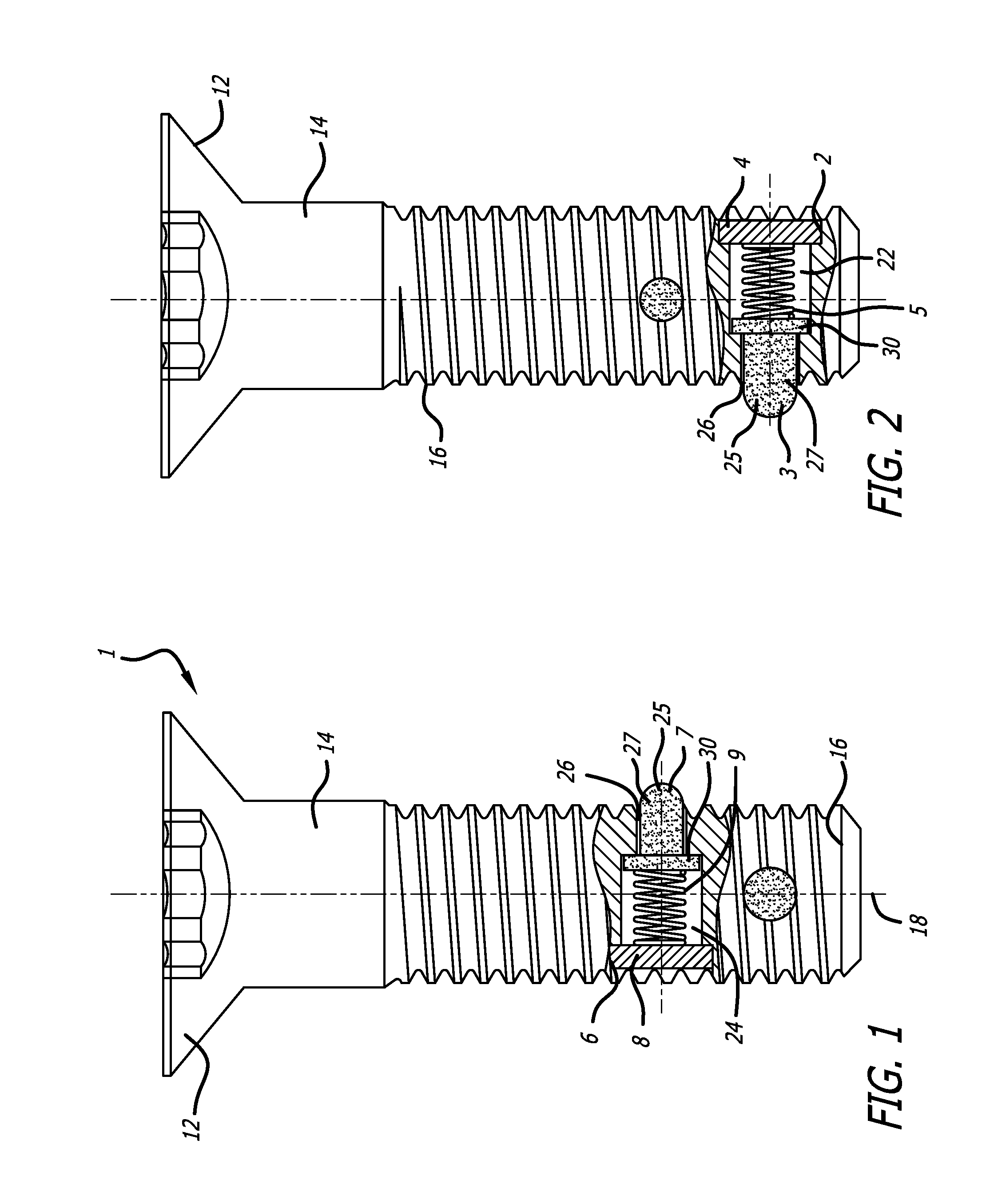
[0007] FIG. 1 is a front view, partially cut-away, of the present invention, showing the hold out pin 7.
[0008] FIG. 2 is a side view, partially cut-away, of the embodiment of FIG. 1, showing the captive pin 3.
[0009] FIG. 3 is a side view of the fastener of FIG. 1 entering a panel;
[0010] FIG. 4 is a side view of the fastener of FIG. 1 having passed through the panel to expose the hold out pin and captive pin;
[0011] FIG. 5 is a side view of the fastener of FIG. 1 where the captive pin locks the fastener in the panel and the hold out pin is retained by the panel; and
[0012] FIG. 6 is a front view of the fastener of FIG. 1, showing the fastener in upright position, being held out by pin 7.
DETAILED DESCRIPTION OF THE PREFERRED EMBODIMENTS
[0013] FIGS. 1 and 2 show a fastener of a first embodiment of the present invention, where the fastener 1 is a flush head screw having a head 12, a neck 14, and a threaded shaft 16 having a longitudinal axis 18. The head may have 6-lobes recess at an upper surface, or a Phillips or screwdriver slot as required, or no slot in the case of bolts. The shaft 16 may have any pitch thread, and the neck may have any length as needed. In the example shown, the head 12 is countersunk to match a recess 17 in a panel 21 so that the head 12 will be flush against the panel 21 at the recess when the fastener 1 is fully driven into the panel 21, although the invention is not so limited and other types of fastener heads and panel recesses are within the scope of the invention.
[0014] The shaft 16 of the fastener 1 is formed with first and second internal cavities 22, 24 spaced axially along the shaft's length. At each cavity is a circular opening 26 that has a smaller diameter than the diameter of the cavity 22, 24, and each circular opening 26 provides an outlet to its respective cavity. Opposite each circular opening 26 is a counter bore 2, 6 that is fitted with a plug 4, 8 that provides a support for the spring action of the pins.
[0015] With further reference to FIGS. 1 and 2, the internal cavities 22, 24 each include an expandable pin 3,7 formed by a spring 5,9 and a cylindrical pin body 27 with a spherical distal end 25 and an annular proximal rim 30. It is to be understood that the particular shapes are not critical to the invention, and that the invention is not limited to these shapes. The radius of the cylindrical body 27 is sized to match the inner radius of the circular opening 26 so as to slide into and out of the opening freely. The outward movements of the pins 3,7 are arrested by the contact of the annular rim 30 against the circular opening 26, such that the pins can only extend out of the shaft 16 a limited distance. This condition leaves the ends 25 of the pins 3, 7 extending outwardly from the shaft 16 a small amount that exceeds the diameter of the shaft.
[0016] The pins 3, 7 are each biased to extend through the circular openings 26 by respective springs 5, 9 that bear against the plugs 4,8 and are aligned so that the axes of the coil springs are aligned with the longitudinal axis of the respective circular opening 26. As shown in FIGS. 1 and 2, the springs 5, 9 bias the pins outward, but also permit the pins to be collapsed or retracted into the respective cavity against the biasing of the springs 5, 9. Once a compressive force is removed, the springs 5, 9 extend the pins 3, 7 until the annular rim 30 of the pin bear against the inner wall of the cavity at the circular opening 26. The captive pin 3 and the hold out pin 7 thus collapse to a position within the fastener shaft 16 when a compressive force is applied, and spring apart to a deployed position when the compressive force is removed.
[0017] Turning to FIGS. 3-6, when the fastener 1 is inserted into the countersunk hole 17 of the panel 21, a tilting of the fastener (FIG. 3) will depress the captive pin 3 to force the captive pin 3 into its chamber 22 and allow the fastener to enter the panel 21. The force of the panel collapses the pin 3 against the bias of the spring 5, allowing the fastener to pass through the straight portion 28 of the countersunk hole 17. The fastener 1 is fully inserted into the panel 21 (FIG. 4), until the shaft 16 of the fastener reemerges from the hole 28. Once the shaft 16 of the fastener passes through the panel 21 and the circular openings 26 are clear of the panel 21, the pins 3, 7 have no compressive force to counteract the expanding force of the springs 5, 9 and the pins expands outward until they reach their maximum extension. In their expanded state, as seen in FIG. 4, the pins' protrusion from the shaft 16 exceeds the diameter of the hole 28. If the hold out pin 7 is depressed again during the withdrawal of the fastener 1, the captive pin 3 prevents the pin from separating from the panel 21 while the hold out pin 7 creates a hold out feature to position the fastener 1 in a perpendicular orientation with respect to the panel 21, as shown in FIGS. 5 and 6.
[0018] While the preferred embodiments of the present invention have been depicted and described, the invention is not limited to the foregoing descriptions and depictions. Rather, one of ordinary skill in the art will readily recognize and appreciate that modifications and substitutions would be possible in connection with the foregoing preferred embodiment, and the scope of the invention is intended to cover all such substitutions and modifications.
* * * * *
D00000
D00001
D00002
D00003
XML
uspto.report is an independent third-party trademark research tool that is not affiliated, endorsed, or sponsored by the United States Patent and Trademark Office (USPTO) or any other governmental organization. The information provided by uspto.report is based on publicly available data at the time of writing and is intended for informational purposes only.
While we strive to provide accurate and up-to-date information, we do not guarantee the accuracy, completeness, reliability, or suitability of the information displayed on this site. The use of this site is at your own risk. Any reliance you place on such information is therefore strictly at your own risk.
All official trademark data, including owner information, should be verified by visiting the official USPTO website at www.uspto.gov. This site is not intended to replace professional legal advice and should not be used as a substitute for consulting with a legal professional who is knowledgeable about trademark law.