Compressor Bypass During Start-up
THALHAUSER; Josef ; et al.
U.S. patent application number 16/272398 was filed with the patent office on 2019-08-22 for compressor bypass during start-up. The applicant listed for this patent is GE Jenbacher GmbH & Co. OG. Invention is credited to Georg ARNOLD, Nikolaus SPYRA, Josef THALHAUSER.
| Application Number | 20190257242 16/272398 |
| Document ID | / |
| Family ID | 61256657 |
| Filed Date | 2019-08-22 |
| United States Patent Application | 20190257242 |
| Kind Code | A1 |
| THALHAUSER; Josef ; et al. | August 22, 2019 |
COMPRESSOR BYPASS DURING START-UP
Abstract
An internal combustion engine comprising at least one turbo charger, which comprises a compressor, at least one bypass valve, through which the compressor can be bypassed by at least a partial stream of air or an air-fuel mixture, and a control unit is provided. The control unit is configured to open or closed loop control the bypass valve. As such, the control unit is configured to at least partially open the at least one bypass valve and keep the at least one bypass valve open during a start of the internal combustion engine. The control unit is also configured to keep the at least one bypass valve open until an engine parameter of the internal combustion engine satisfies a predetermined startup criterion.
| Inventors: | THALHAUSER; Josef; (Jenbach, AT) ; SPYRA; Nikolaus; (Jenbach, AT) ; ARNOLD; Georg; (Jenbach, AT) | ||||||||||
| Applicant: |
|
||||||||||
|---|---|---|---|---|---|---|---|---|---|---|---|
| Family ID: | 61256657 | ||||||||||
| Appl. No.: | 16/272398 | ||||||||||
| Filed: | February 11, 2019 |
| Current U.S. Class: | 1/1 |
| Current CPC Class: | F02B 37/16 20130101; F02D 2200/0402 20130101; F02B 37/162 20190501; F02D 41/062 20130101; F02D 41/0002 20130101; F02D 41/0007 20130101; F02D 41/061 20130101 |
| International Class: | F02B 37/16 20060101 F02B037/16; F02D 41/00 20060101 F02D041/00 |
Foreign Application Data
| Date | Code | Application Number |
|---|---|---|
| Feb 21, 2018 | EP | 18157811.3 |
Claims
1. An internal combustion engine comprising: at least one turbo charger, which comprises a compressor; at least one bypass valve, through which the compressor can be bypassed by at least a partial stream of air or an air-fuel mixture; and a control unit configured to open or closed loop control the bypass valve; wherein the control unit is configured to at least partially open the at least one bypass valve and keep it open during a start of the internal combustion engine, and wherein the control unit is configured to keep the at least one bypass valve open until an engine parameter of the internal combustion engine satisfies a predetermined startup criterion.
2. The internal combustion engine as set forth in claim 1, wherein the engine parameter is a pressure difference before and after the compressor in flow direction, and wherein the predetermined startup criterion is a predetermined pressure difference.
3. The internal combustion engine as set forth in claim 1, wherein the engine parameter is a rotational speed of the turbo charger or the internal combustion engine, wherein the predetermined startup criterion is a lower threshold, and wherein the control unit keeps the at least one bypass valve open until the rotational speed attains or exceeds the predetermined lower threshold.
4. The internal combustion engine as set forth in claim 1, wherein the engine parameter is a time since a beginning of a start procedure, wherein the predetermined startup criterion is a lower threshold, and wherein the control unit keeps the at least one bypass valve open until the time since the start attains or exceeds the predetermined lower threshold.
5. The internal combustion engine as set forth in claim 1, wherein the predetermined startup criterion is chosen such that it is fulfilled at such a point in time, when the internal combustion engine is running without the action of an auxiliary drive.
6. The internal combustion engine as set forth in claim 1, wherein at least one upstream sensor is provided in flow upstream of the compressor, and wherein the at least one upstream sensor (6) is configured to provide the control unit with a characteristic signal for an upstream pressure.
7. The internal combustion engine as set forth in claim 1, wherein at least one downstream sensor is provided in flow direction downstream of the compressor, and wherein the at least one downstream sensor is configured to provide the control unit with a characteristic signal for a downstream pressure.
8. The internal combustion engine as set forth in claim 6, wherein the control unit is configured to determine a pressure difference, from measurement of the at least one downstream sensor and the measurements of the at least one upstream sensor.
9. The internal combustion engine as set forth in claim 1, wherein at least one rotational speed sensor is provided to determine a characteristic signal for the rotational speed of the internal combustion engine or the turbo charger, and wherein the control unit can be provided with the characteristic signal of the at least one rotational speed sensor.
10. The internal combustion engine as set forth in claim 1, wherein the control unit is configured to open or closed loop control the opening degree of the bypass valve.
11. The internal combustion engine as set forth in claim 1, wherein the control unit is a mechanical and/or electronic control unit.
12. The internal combustion engine as set forth in claim 1, wherein at least one further component of the internal combustion engine can be bypassed by the at least one bypass valve.
13. A method for operating an internal combustion engine with at least one turbo charger as set forth in claim 1, the method comprising: providing a bypass valve for bypassing a compressor of the at least one turbo charger; and keeping the bypass valve at least partially open during a start of the internal combustion engine until an engine parameter of the internal combustion engine satisfies a predetermined startup criterion.
Description
FIELD OF TECHNOLOGY
[0001] The present disclosure relates to an internal combustion engine according to the characteristics of the classifying portion of claims 1 and a method for operating an internal combustion engine.
BACKGROUND
[0002] It is known by the state of the art to prevent an internal combustion engine with at least one turbo charger. The turbo charger is provided with a compressor, wherein by means of the compressor air or an air-fuel mixture can be charged. It is also known to provide at least one bypass valve, through which the compressor can be bypassed by at least a partial stream of air or an air-fuel mixture. This bypass valve can be open or closed loop controlled by a control unit. In this way the charge pressure of the internal combustion engine and therefore the power-output of the internal combustion engine can be open or closed loop controlled with relatively short reaction times. Thereby the bypass valve will be closed if more power or a higher rotational speed of the internal combustion engine is required.
[0003] A disadvantage is that if the internal combustion engine is started, the air or the air-fuel mixture has to be conveyed to the combustion chambers. In the first phase of the engine start the turbo charger or more specific the compressor has a low rotational speed and behaves as a flow restriction for the air or air-fuel mixture bound for the combustion chambers. Because of this behavior of the compressor of the turbo charger the flow of air or an air-fuel mixture is delayed during the starting process until the compressor of the turbocharger builds up pressure when the turbocharger reaches a certain rotational speed. This leads to a relative long starting time of the internal combustion engine as the turbocharger has a high mass moment of inertia.
SUMMARY OF THE DISCLOSURE
[0004] The object of the present application is to provide an internal combustion engine and a method for operating an internal combustion engine, wherein the time for starting the internal combustion engine is significantly reduced.
[0005] This object is accomplished according to the subject disclosure with an internal combustion engine having the characteristics of claim 1 and with a method for operating an internal combustion engine having the characteristics of claim 13.
[0006] By means of the subject disclosure air or an air-fuel mixture, which is required for combustion, can--choosing the path of least resistance--flow as quickly as possible to a combustion zone, which is provided for the combustion, this could for example be a combustion chamber of the internal combustion engine.
[0007] For starting the internal combustion engine the internal combustion engine is driven--for example--by an auxiliary drive, till air or an air-fuel mixture arrives at the combustion zone, which is provided for an ignition. As soon as the air or the air-fuel mixture arrives at the place provided for an ignition, ignition can take place and the internal combustion engine starts running without any external help (for example without the help of an auxiliary drive).
[0008] As soon the internal combustion engine starts running without any external help also the turbo charger starts its operation. In other words, the compressor starts to convey the air or air-fuel flow and the air or air-fuel is not only sucked by the internal combustion engine.
[0009] The disclosure is based on the knowledge that during the start of the internal combustion engine, wherein air or an air-fuel mixture is sucked by the internal combustion engine, the time for starting can be reduced by having the air or air-fuel mixture bypass the compressor keeping the bypass valve open till the engine parameter of the internal combustion engine satisfies a predetermined startup criterion. In this way the air or air-fuel flow can bypass the compressor during at least the substantial phase of the starting procedure, whereby the flow resistance is reduced.
[0010] The air or air-fuel flow arrives at the provided zone for ignition faster. It should be noted that the flow of air or air-fuel flow will be reverse as soon as the compressor of the turbo charger starts its operation. This is the consequence of the fact that the presser downstream of the compressor is higher than upstream the compressor.
[0011] Therefore, according to the disclosure a control unit is provided, which is configured to open the at least one bypass valve at least partially and keep it open during a start of the internal combustion engine, characterised in that the control unit is configured to keep the at least one bypass unit open till an engine parameter of the internal combustion engine satisfies a predetermined startup criterion.
[0012] The bypass valve can be arranged in a bypass conduct bypassing the compressor. However, it is in principle also possible to arrange incoming and outgoing conducts for the compressor in such a way that only the bypass valve itself is necessary.
[0013] The embodiments of the disclosure are defined by the depending claims.
[0014] The disclosure can be used for internal combustion engines having one turbo charger or more than one. By the use of more than one turbo charger, the turbo chargers can be connected in series or in parallel.
[0015] It can be provided that the engine parameter is a pressure difference before and after the compressor in flow direction, wherein the predetermined startup criterion is a predetermined pressure difference. This predetermined pressure difference can for example be determined by tests.
[0016] In an embodiment it can be provided that the engine parameter is a rotational speed of the turbo charger or the internal combustion engine, wherein the predetermined startup criterion is a lower threshold, wherein the control unit keeps the at least one bypass valve open till the rotational speed attains or exceeds the predetermined lower threshold.
[0017] Alternatively or additionally it can be provided that the engine parameter is a time since beginning of the starting procedure, wherein the predetermined startup criterion is a lower threshold, wherein the control unit keeps the at least one bypass valve open till the time since the beginning of the starting procedure attains or exceeds the predetermined lower threshold. The beginning of the start procedure can for example be the point in time where an auxiliary drive is activated.
[0018] It can be provided that the predetermined startup criterion is chosen such that it is fulfilled at such a point in time, when the internal combustion engine is running without the action of an auxiliary drive.
[0019] At an embodiment of the disclosure it is provided that one upstream sensor is provided in flow direction upstream of the compressor, wherein the at least one upstream sensor is configured to provide the control unit with a characteristic signal for an upstream pressure. Alternatively it can also be provided that a pressure value is provided for the control unit, which is characteristic for the ambient pressure of the internal combustion engine.
[0020] It can be provided that at least one downstream sensor is provided in flow direction downstream of the compressor, wherein the at least one downstream sensor is configured to provide the control unit with a characteristic signal for a downstream pressure.
[0021] In addition it can be provided, that the control unit is configured to determine a pressure difference, from measurement of the at least one downstream sensor and the measurements of the at least one upstream sensor. In many instances it is, however, possible to not use an upstream sensor and to use the usual ambient pressure for determination of the pressure difference.
[0022] It can also be provided that at least one rotational speed sensor is provided to determine a characteristic signal for the rotational speed of the internal combustion engine or the turbo charger, wherein the control unit can be provided with the characteristic signal of the at least one rotational speed sensor.
[0023] In a further embodiment of the disclosure it can be provided that the control unit is configured to open or closed loop control the opening degree of the bypass valve.
[0024] It can be provided that that the control unit is a mechanical and/or electronic control unit. A simple example for a mechanical control unit would be a spring pre-load for a check valve, wherein the pre-load of the spring is chosen such that the check valve closes when the internal combustion engine starts to run on its own, in other words, when the pressure downstream of the bypass will increase above a pressure value upstream of the bypass.
[0025] Further, it can be provided that at least one further component of the internal combustion engine can be bypassed by the at least one bypass valve. For example also an intercooler would be a further component that could be bypassed.
[0026] Furthermore protection is sought for a method for operating an internal combustion engine, wherein a bypass valve for bypassing a compressor of the at least one turbo charger is provided, which is at least partially kept open during a start of the internal combustion engine till an engine parameter of the internal combustion engine satisfies a predetermined startup criterion.
BRIEF DESCRIPTION OF THE DRAWINGS
[0027] Further details of the present disclosure will be described with reference to the specific description hereinafter. In the drawing:
[0028] FIG. 1 shows a first embodiment of an international combustion engine,
[0029] FIG. 2 shows second embodiment of an international combustion engine, and
[0030] FIG. 3 shows third embodiment of an international combustion engine.
DETAILED DESCRIPTION
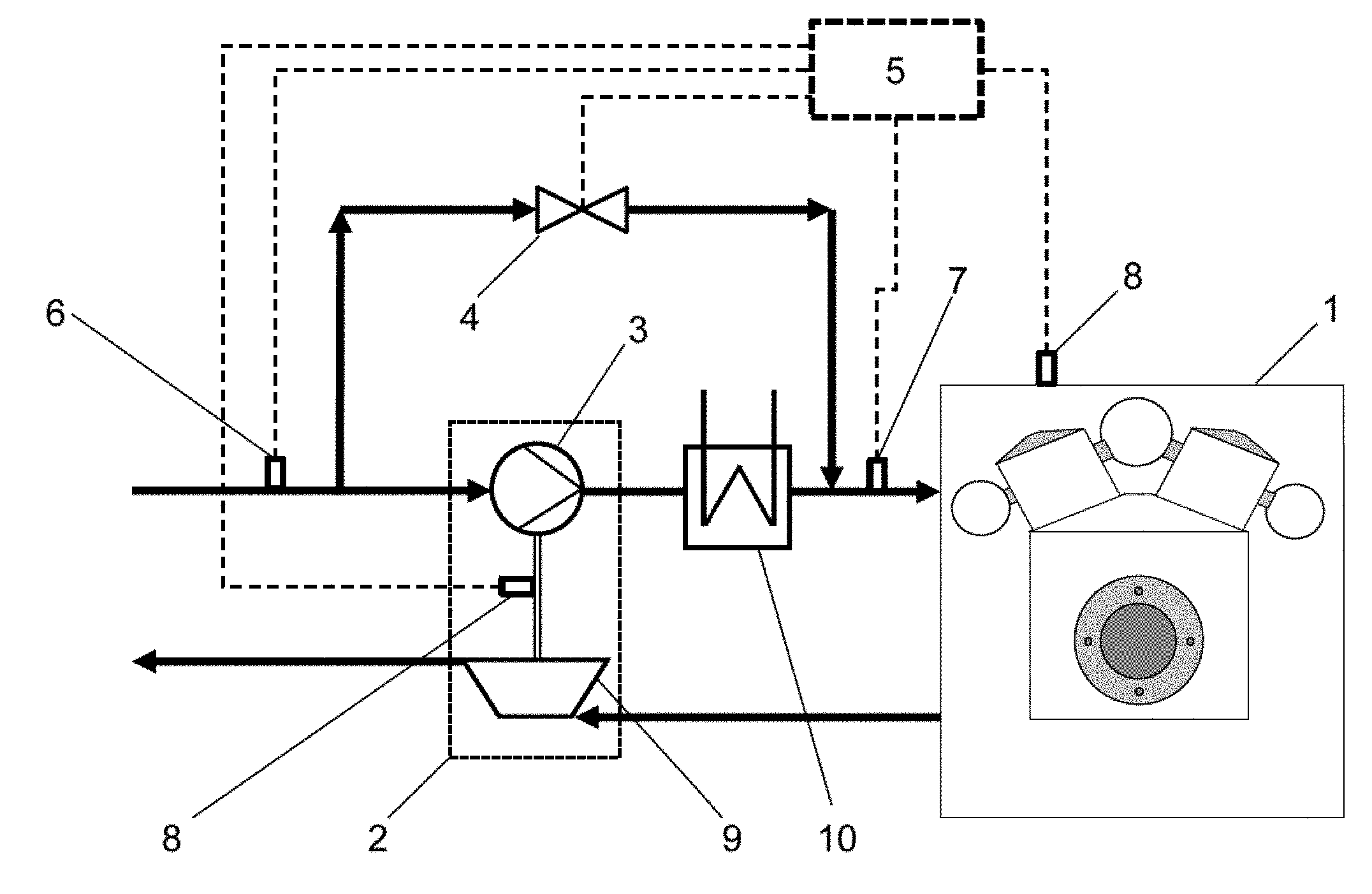
[0031] FIG. 1 shows a first embodiment of an international combustion engine 1, wherein the internal combustion engine 1 comprises a turbo charger 2. By means of the turbo charger 2 air or an air-fuel mixture can be charged for the combustion in the internal combustion engine 1. This air or air-fuel mixture is charged by the compressor 3 of the turbo charger 2. The turbo charger 2 further comprises an exhaust gas turbine 9, which is connected to the compressor 3 by a shaft. The exhaust gas turbine 9 is driven by exhaust gas coming from the internal combustion engine 1, where the exhaust gas is produced combusting of the air fuel mixture. This combustion normally takes place in the combustion chambers of the internal combustion engine 1 (not shown by the figures). For combustion in mixed charged internal combustion engines a charged air-fuel mixture is fed to the internal combustion engine 1. For combustion in charged internal combustion engines having a fuel port injection a charged air is fed to the internal combustion engine 1, a fuel is separately fed to the internal combustion engine 1 by means of port injection nozzles. When charging air or an air-fuel mixture the air or the air-fuel mixture also is heated by the compression operation. For reducing the temperature of the air or the air-fuel mixture an intercooler 10 is provided.
[0032] The compressor 3 and the intercooler 10 can be bypassed by means of a bypass conduct and a bypass valve 4. This bypass valve 4 is connected by a signal line (presented by the dotted line) with a control unit 5, which is configured to open or closed loop control the bypass valve 4. Furthermore an upstream sensor 6 is provided, which is connected with the control unit 5 by usage of a signal line. The upstream sensor 6 is configured to provide the control unit 5 with a characteristic signal for an upstream pressure (downstream of the compressor 3). Also a downstream sensor 7 is provided which is also connected to the control unit 5 by a signal line. The downstream sensor 7 is configured to provide the control unit 5 with a characteristic signal for a downstream pressure (upstream of the compressor 3). The control unit 5 is configured to determine a pressure difference, from measurement of the downstream sensor 7 and the upstream sensor 6. This pressure difference can be used by the control unit 5 for control an opening degree of the bypass valve 5.
[0033] During a startup of the internal combustion engine 1 the control unit is configured (according to the disclosure) to keep the bypass valve 4 partially open till an engine parameter of the internal combustion engine 1 satisfies a predetermined startup criterion. This startup criterion can be characteristic for a state were the internal combustion engine runs on its own, for example without the help of an auxiliary drive (not shown in the figures). Such a startup criterion could--for example--be a threshold value for the above mentioned pressure difference. If the pressure measured by the downstream sensor 7 exceeds the measured pressure of the upstream sensor 6 (taking into account measurement inaccuracy) this can be characteristic for a start of the internal combustion engine (i.e. threshold value 0). It is not absolutely necessary to determine a pressure upstream of the compressor 3 by an upstream sensor 6. It can also be provided that an ambient pressure is stored at the control unit 5, which approximates the upstream pressure of the compressor 3.
[0034] Other examples for a startup criterion would be a predetermined threshold for a rotary speed of the internal combustion engine 1 or the turbo charger 2. For checking if this criterion is fulfilled already provided rotary speed sensors 8 can be used. Another possibility for a startup criterion is that if the time since the start of the operation attains or exceeds a predetermined lower threshold the control unit 5 does not longer keep the bypass valve 4 open (i.e. closes it).
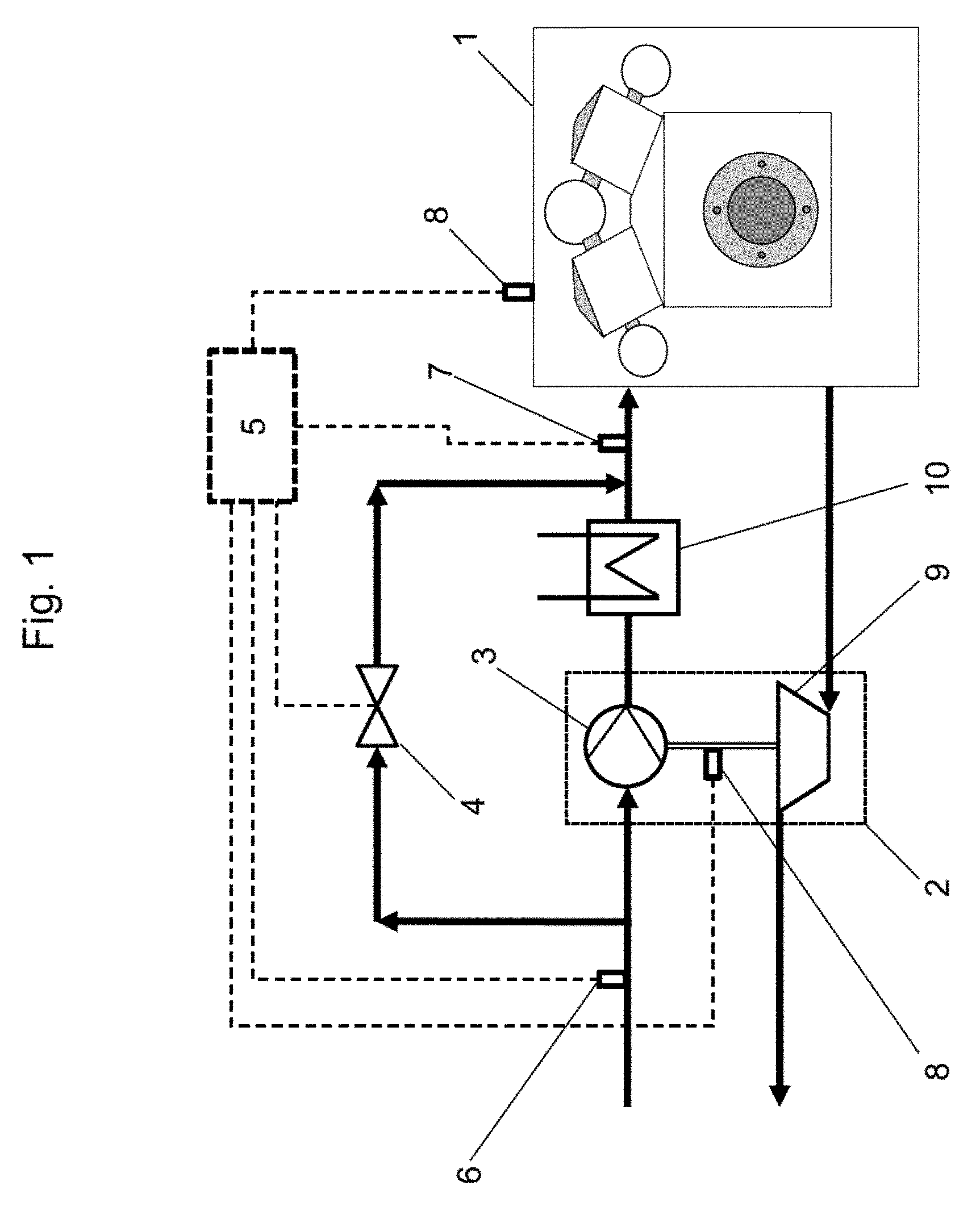
[0035] FIG. 2 shows a second embodiment of an international combustion engine 1, wherein the bypass valve 4 is provided with a check valve 11. The internal combustion engine 1 the turbo charger 2 and the intercooler 10 correspond to the embodiment of FIG. 1. The check valve 11 of FIG. 2 is configured with a spring preloading to be kept open during starting of the internal combustion engine 1, i.e. when the pressure downstream of the compressor 3 is be lower than the upstream pressure because the internal combustion engine 1 sucks air or an air-fuel mixture.
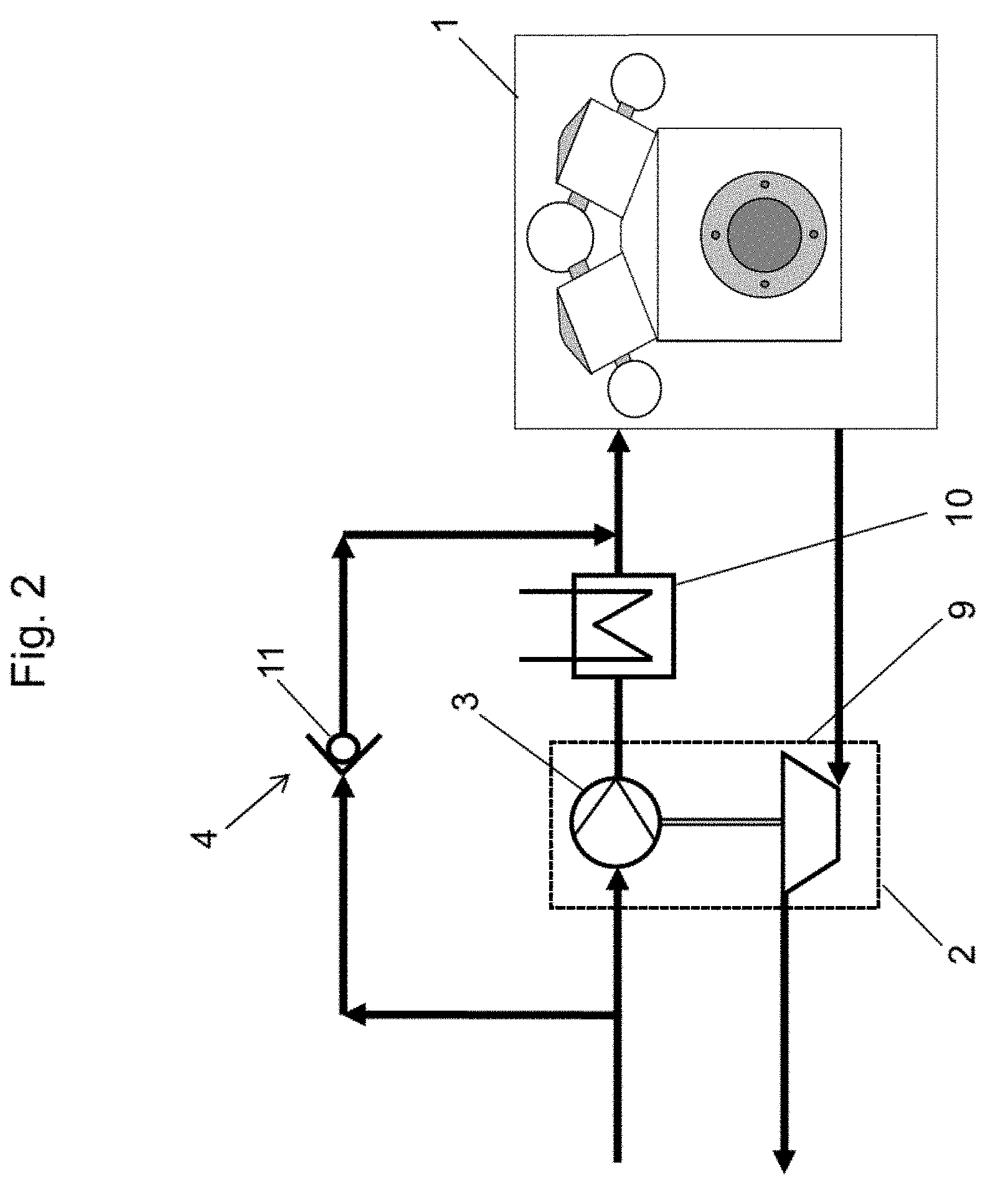
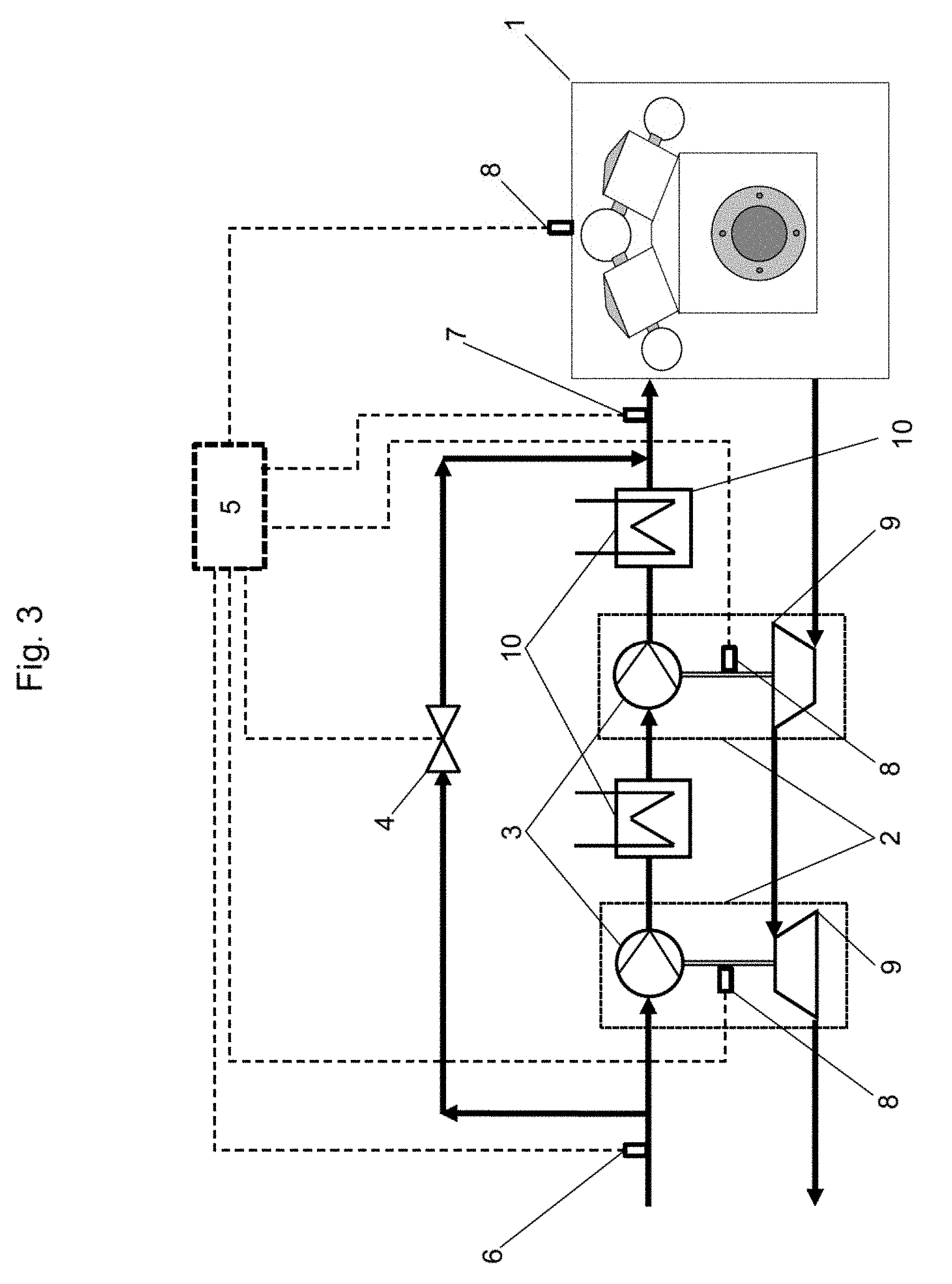
[0036] The third embodiment of an internal combustion engine 1 of FIG. 3 shows an example, wherein further components of the internal combustion engine are bypassed by the bypass valve 4. This embodiment teaches the use of two turbo chargers 2, wherein each turbo charger comprises a compressor, an exhaust gas turbine 9, a connection between the compressor 3 and the exhaust gas turbine 9 by a shaft, a rotational speed sensor 8 for determine a characteristic signal for each turbo charger 2 and an intercooler 10 downstream of each turbo charger 2. The rotational speed sensors 8 are configured to provide the control unit 5 with a signal, which can be used by the control unit 5 for open or closed loop control of the bypass valve 4. This control scheme is similar to the control scheme of FIG. 1. However, in contrast to FIG. 1, FIG. 3 teaches to bypass two turbo chargers 2 and two intercoolers 10 by means of the bypass valve 4 during a starting procedure of the internal combustion engine 1.
* * * * *
D00000
D00001
D00002
D00003
XML
uspto.report is an independent third-party trademark research tool that is not affiliated, endorsed, or sponsored by the United States Patent and Trademark Office (USPTO) or any other governmental organization. The information provided by uspto.report is based on publicly available data at the time of writing and is intended for informational purposes only.
While we strive to provide accurate and up-to-date information, we do not guarantee the accuracy, completeness, reliability, or suitability of the information displayed on this site. The use of this site is at your own risk. Any reliance you place on such information is therefore strictly at your own risk.
All official trademark data, including owner information, should be verified by visiting the official USPTO website at www.uspto.gov. This site is not intended to replace professional legal advice and should not be used as a substitute for consulting with a legal professional who is knowledgeable about trademark law.