Fence Having Hydrophilic Material
MOON; Myoung-Woon ; et al.
U.S. patent application number 16/127165 was filed with the patent office on 2019-08-22 for fence having hydrophilic material. The applicant listed for this patent is KOREA INSTITUTE OF SCIENCE AND TECHNOLOGY. Invention is credited to Seohyun CHO, O Chang KWON, Kwang Ryeol LEE, Young A LEE, Myoung-Woon MOON.
| Application Number | 20190257050 16/127165 |
| Document ID | / |
| Family ID | 67616717 |
| Filed Date | 2019-08-22 |


| United States Patent Application | 20190257050 |
| Kind Code | A1 |
| MOON; Myoung-Woon ; et al. | August 22, 2019 |
FENCE HAVING HYDROPHILIC MATERIAL
Abstract
The present disclosure relates to a fence having a hydrophilic material, and according to an embodiment of the present disclosure, there is an effect in collecting oil or hazardous & noxious substances quickly and efficiently while minimizing the pressure caused by water, by forming the fence from a material that allows water to penetrate while disallowing oil to penetrate. Additionally, there is an effect in preventing oil spill phenomena caused by damage or unbalance of the fence by reducing the water pressure applied to the fence due to water penetration even when a strong water pressure acts on the fence, for example, strong tidal currents occur and the fence is towed at high speeds to collect oil.
| Inventors: | MOON; Myoung-Woon; (Seoul, KR) ; LEE; Kwang Ryeol; (Seoul, KR) ; KWON; O Chang; (Seoul, KR) ; CHO; Seohyun; (Seoul, KR) ; LEE; Young A; (Seoul, KR) | ||||||||||
| Applicant: |
|
||||||||||
|---|---|---|---|---|---|---|---|---|---|---|---|
| Family ID: | 67616717 | ||||||||||
| Appl. No.: | 16/127165 | ||||||||||
| Filed: | September 10, 2018 |
| Current U.S. Class: | 1/1 |
| Current CPC Class: | C02F 2103/007 20130101; E02B 15/0864 20130101; C02F 1/40 20130101; E02B 15/0807 20130101; E02B 15/0814 20130101; E02B 15/0857 20130101; C02F 2103/08 20130101; E02B 15/06 20130101 |
| International Class: | E02B 15/08 20060101 E02B015/08 |
Foreign Application Data
| Date | Code | Application Number |
|---|---|---|
| Feb 19, 2018 | KR | 10-2018-0019563 |
Claims
1. A fence having a hydrophilic material, comprising: a float that floats in water; and a skirt coupled to at least one of top and bottom of the float, wherein at least one of the float and the skirt is made of a hydrophilic material that allows for selective penetration of a hydrophilic fluid, or has a surface to which a hydrophilic separation membrane made of a hydrophilic material is coupled.
2. The fence having a hydrophilic material according to claim 1, wherein comprises a support composed of a plurality of frames coupled to support the surface of at least one of the float and the skirt in order to reinforce strength. 15
3. The fence having a hydrophilic material according to claim 1, wherein in case that the hydrophilic separation membrane made of a hydrophilic material is coupled to the surface, the float includes: an inner floating body continuously extending in spiral shape.
4. The fence having a hydrophilic material according to claim 1, wherein in case that the hydrophilic separation membrane made of a hydrophilic material is coupled to the surface, the float includes: a plurality of tube bodies spaced apart from each other; and at least one disk member through which the plurality of tube bodies is coupled so that the plurality of tube bodies is held together.
5. The fence having a hydrophilic material according to claim 1, wherein in case that the hydrophilic separation membrane made of a hydrophilic material is coupled to the surface, the float includes: an inner floating body formed of a tube including a plurality of through-holes.
6. The fence having a hydrophilic material according to claim 1, wherein in case that the hydrophilic separation membrane made of a hydrophilic material is coupled to the surface, the float includes: a plurality of tube bodies arranged in parallel; and a coil member into which the plurality of tube bodies is inserted so that the plurality of tube bodies is supported.
7. The fence having a hydrophilic material according to claim 1, wherein comprises a reinforcing material coupled to at least one of the float and the skirt to reinforce strength.
Description
CROSS-REFERENCE TO RELATED APPLICATIONS
[0001] This application claims priority under 35 U.S.C. .sctn. 119 to Korean Patent Application No. 10-2018-0019563 filed on Feb. 19, 2018 in the Korean Intellectual Property Office, the disclosure of which is incorporated herein by reference in its entirety.
TECHNICAL FIELD
[0002] The present disclosure relates to a fence having a hydrophilic material, and more particularly, a fence having a hydrophilic material in which a hydrophilic oil separating material is used for a float and a skirt that constitute the fence so that the entire fence has a function to allow water to penetrate while disallowing oil to penetrate, thereby stably trapping oil or hazardous & noxious substances in water quickly and reliably even at areas with strong tidal currents of high velocity flow or high waves.
BACKGROUND
[0003] When oil or hazardous & noxious substance (HNS) spill accidents occur in seas and rivers, oil or HNS spreads out rapidly on the surface of the seas and rivers, causing serious environmental pollution.
[0004] Accordingly, when oil or HNS spill accidents occur, it is important to remove quickly.
[0005] In general, when oil is spilled on seas or rivers, after flows of marine currents are calculated and a primary spill barrier is installed by installing an oil fence, an emulsifying agent is sprayed to cause oil contained and collected by the oil fence to sink in deep water, or oil is collected using oil collection equipment such as an oil skimmer and absorbent fabrics.
[0006] However, in the case of conventional oil fence, at areas with strong tidal currents or high waves, the fence often gets unbalanced due to the water pressure and its effect sharply reduces, and thus the conventional oil fence is difficult to use.
RELATED LITERATURES
Patent Literatures
[0007] Korean Patent No. 10-1149032 titled `Oil fence and method for storing same`
SUMMARY
[0008] The present disclosure is designed under the above-described background, and therefore the present disclosure is directed to providing a fence having a hydrophilic material in which the fence is made of a material that allows water to penetrate while disallowing oil to penetrate, thereby collecting oil or hazardous & noxious substance (HNS) quickly and efficiently while minimizing the pressure caused by water.
[0009] The present disclosure is further directed to providing a fence having a hydrophilic material in which the water pressure applied to the fence reduces due to water penetration even when a strong water pressure acts on the fence, for example, strong tidal currents occur and the fence is towed at high speeds to collect oil, thereby preventing oil spill phenomena caused by damage or unbalance of the fence.
[0010] The object of the present disclosure is not limited thereto, and another object not mentioned herein will be clearly understood by those skilled in the art from the following description.
[0011] To achieve these objects, an embodiment of the present disclosure provides a fence having a hydrophilic material including a float that floats in water, and a skirt coupled to at least one of top and bottom of the float, wherein at least one of the float and the skirt is made of a hydrophilic material that allows for selective penetration of a hydrophilic fluid, or has a surface to which a hydrophilic separation membrane made of a hydrophilic material is coupled.
[0012] Additionally, there is provided the fence having a hydrophilic material including a support composed of a plurality of frames coupled to support the surface of at least one of the float and the skirt in order to reinforce strength.
[0013] Additionally, there is provided the fence having a hydrophilic material wherein in case that the hydrophilic separation membrane made of a hydrophilic material is coupled to the surface, the float includes an inner floating body continuously extending in spiral shape.
[0014] Additionally, there is provided the fence having a hydrophilic material wherein in case that the hydrophilic separation membrane made of a hydrophilic material is coupled to the surface, the float includes a plurality of tube bodies spaced apart from each other, and at least one disk member through which the plurality of tube bodies is coupled so that the plurality of tube bodies is held together.
[0015] Additionally, there is provided the fence having a hydrophilic material wherein in case that the hydrophilic separation membrane made of a hydrophilic material is coupled to the surface, the float includes an inner floating body formed of a tube including a plurality of through-holes.
[0016] Additionally, there is provided the fence having a hydrophilic material wherein in case that the hydrophilic separation membrane made of a hydrophilic material is coupled to the surface, the float includes a plurality of tube bodies arranged in parallel, and a coil member into which the plurality of tube bodies is inserted so that the plurality of tube bodies is supported.
[0017] According to an embodiment of the present disclosure, there is an effect in collecting oil or HNS quickly and efficiently while minimizing the pressure caused by water, by forming the fence from a material that allows water to penetrate while disallowing oil to penetrate.
[0018] Additionally, there is an effect in preventing oil spill phenomena caused by damage or unbalance of the fence by reducing the water pressure applied to the fence due to water penetration even when a strong water pressure acts on the fence, for example, strong tidal currents occur and the fence is towed at high speeds to collect oil.
BRIEF DESCRIPTION OF THE DRAWINGS
[0019] FIG. 1 is a diagram showing a problem of conventional oil fence and oil containment.
[0020] FIG. 2 is a diagram showing a fence having a hydrophilic material according to an embodiment of the present disclosure.
[0021] FIG. 3 is a diagram showing a water penetration phenomenon of a fence having a hydrophilic material according to an embodiment of the present disclosure.
[0022] FIG. 4 is a diagram showing a fence having a hydrophilic material according to another embodiment of the present disclosure.
[0023] FIG. 5 is a diagram showing a fence having a hydrophilic material according to still another embodiment of the present disclosure.
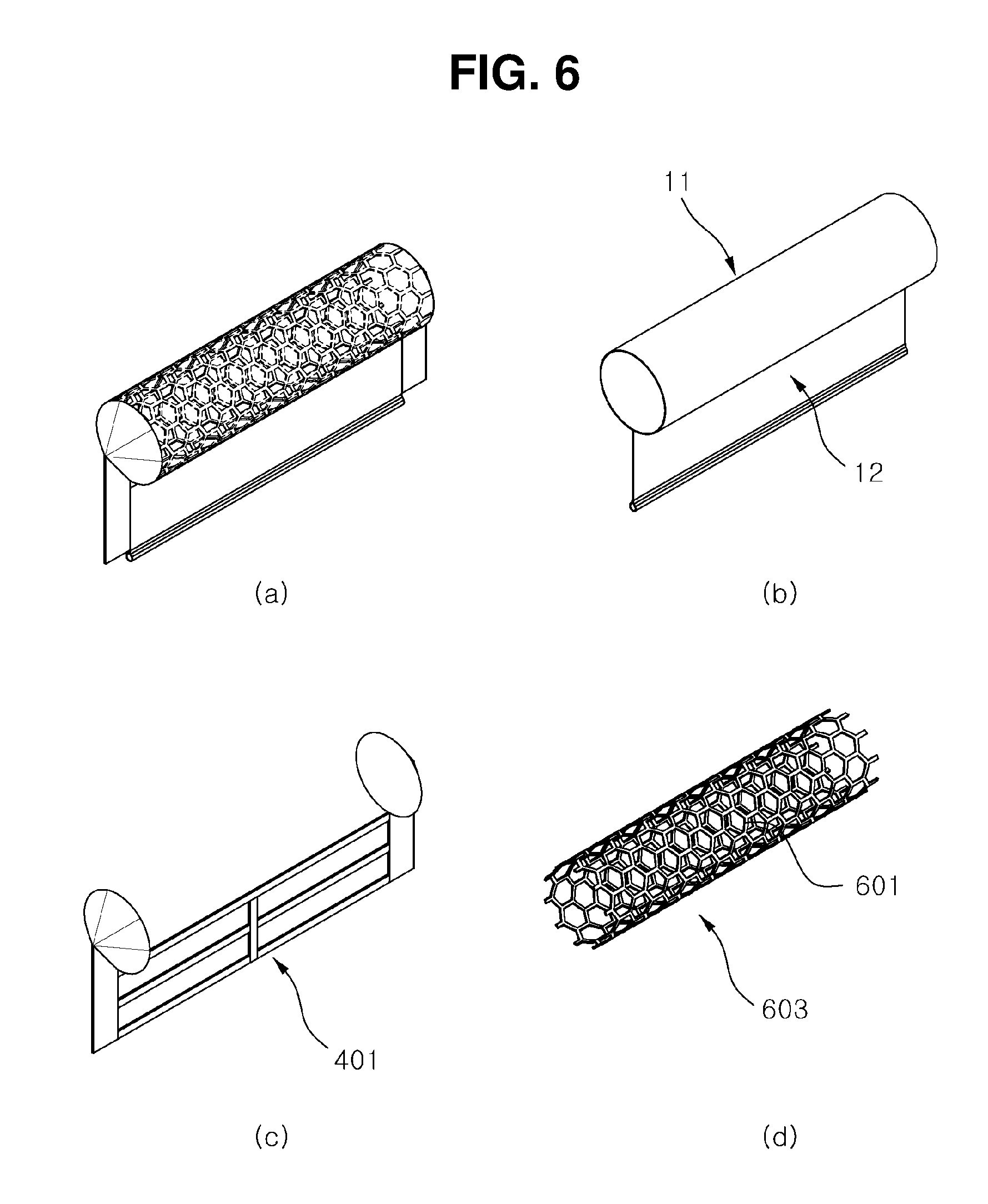
[0024] FIG. 6 is a diagram showing a fence having a hydrophilic material according to further another embodiment of the present disclosure.
[0025] FIG. 7 is a diagram showing a fence having a hydrophilic material according to yet another embodiment of the present disclosure.
[0026] FIG. 8 is a diagram showing a relationship between water pressure and distance of fabric in a fence having a hydrophilic material according to an embodiment of the present disclosure.
DETAILED DESCRIPTION OF EMBODIMENTS
[0027] Hereinafter, certain embodiments of the present disclosure will be described in detail through exemplary drawings. It should be noted that in adding reference symbols to elements of each drawing, like elements have like reference symbols if possible even though they are indicated on different drawings. Additionally, in describing the present disclosure, when certain details of relevant well-known configuration or function are determined to render the subject matter of the present disclosure vague, its detailed description is omitted herein.
[0028] Furthermore, in describing the elements of the present disclosure, the terms `first`, `second`, A, B, (a), (b), and the like may be used. These terms are only used to distinguish one element from another, and the nature of the corresponding element or its turn or order is not limited by the term. It should be understood that when an element is referred to as being "connected", "coupled" or "linked" to another element, it may be directly connected or linked to other element, but intervening elements may be "connected", "coupled" or "linked" between each element.
[0029] FIG. 1 is a diagram showing a problem of conventional oil fence and oil containment. FIG. 2 is a diagram showing a fence having a hydrophilic material according to an embodiment of the present disclosure. FIG. 3 is a diagram showing a water penetration phenomenon of the fence having a hydrophilic material according to an embodiment of the present disclosure. FIG. 4 is a diagram showing a fence having a hydrophilic material according to another embodiment of the present disclosure. FIG. 5 is a diagram showing a fence having a hydrophilic material according to still another embodiment of the present disclosure. FIG. 6 is a diagram showing a fence having a hydrophilic material according to further another embodiment of the present disclosure. FIG. 7 is a diagram showing a fence having a hydrophilic material according to yet another embodiment of the present disclosure. FIG. 8 is a diagram showing a relationship between water pressure and distance of fabric in the fence having a hydrophilic material according to an embodiment of the present disclosure.
[0030] As shown in these drawings, the fence 10 having a hydrophilic material according to an embodiment of the present disclosure includes a float 11 that floats in the water, and a skirt 12 coupled to at least one of top and bottom of the float 11, wherein at least one of the float 11 and the skirt 12 is made of a hydrophilic material that allows for selective penetration of a hydrophilic fluid, or has a surface to which a hydrophilic separation membrane made of a hydrophilic material is coupled.
[0031] In conventional oil fence, as shown in FIG. 1, when strong tidal currents occur, or the oil fence (a float 701 and a skirt 702) is towed at high speeds to collect oil, the oil fence (the float 701 and the skirt 702) gets damaged or unbalanced due to a strong water pressure applied to the oil fence (the float 701 and the skirt 702), resulting in oil spills, but according to embodiments of the present disclosure, these problems can be solved.
[0032] Hereinafter, each element will be described in detail.
[0033] The float 11 is formed to float on the surface of water, and may be manufactured in the shape of a cylinder and a polygonal pillar, and the length of the float 11 may vary as well.
[0034] Of course, to improve the buoyancy of the float 11, for example, air pocket of rubber or vinyl may be installed inside or outside of the float 11.
[0035] The float 11 is made of a hydrophilic material that allows for selective penetration of a hydrophilic fluid, or has a surface to which a hydrophilic separation membrane made of a hydrophilic material is coupled.
[0036] Here, the hydrophilic material includes natural fibers (cotton, pulp, cellulose, rayon), polymers (acrylic, polypropylene (PP), polystyrene (PS), polyurethane (PU)), or metals.
[0037] Meanwhile, the hydrophilic separation membrane made of the hydrophilic material may have, for example, a porous material surface-treated to have hydrophilicity.
[0038] Furthermore, the hydrophilic separation membrane may have pores of 2 .mu.m to 500 .mu.m.
[0039] Additionally, the hydrophilic separation membrane may have, on the surface, nano protrusion structures having the diameter of 1 to 100 nanometers made of metal or polymer such as polyurethane, polypropylene, polystyrene and acrylic fiber.
[0040] Meanwhile, the hydrophilic separation membrane may be formed with the thickness of 10 .mu.m to 1 cm.
[0041] The hydrophilic separation membrane may be formed in multiple layers.
[0042] Subsequently, the skirt 12 is coupled to at least one of top and bottom of the float 11, and the drawings show an example in which the skirt 12 is coupled to the bottom of the float 11.
[0043] Of course, the skirt 12 is also made of a hydrophilic material that allows for selective penetration of a hydrophilic fluid, or has a surface to which a hydrophilic separation membrane made of a hydrophilic material is coupled.
[0044] Meanwhile, a weight member may be coupled and fixed to the bottom of the skirt 12, and the weight member may be fixed into a coupling hole formed on the bottom of the skirt 12, or may be connected and fixed to the bottom of the skirt 12 with a fixing member such as a rope or a hanger loop.
[0045] Additionally, a reinforcing material may be coupled to at least one of the float 11 and the skirt 12, and the reinforcing material performs a function to reinforce the strength of at least one of the float 11 and the skirt 12.
[0046] For example, the reinforcing material may be formed covering the entirety with a material such as a glass fiber mesh, or may be formed in the shape of a band of PP, PC and PE.
[0047] Meanwhile, the fence having a hydrophilic material according to an embodiment of the present disclosure includes a support 401 composed of a plurality of frames coupled to support the surface of at least one of the float 11 and the skirt 12 in order to reinforce the strength.
[0048] Of course, as shown in the drawings, the support 401 may be provided to support both the float 11 and the skirt 12, and may be provided to support only one of the float 11 and the skirt 12.
[0049] The support 401 may be made of, for example, vinyl, fabric, and metal.
[0050] Meanwhile, in case that the fence having a hydrophilic material according to an embodiment of the present disclosure has a surface to which a hydrophilic separation membrane made of a hydrophilic material is coupled, the float 11 includes an inner floating body 403 continuously extending in spiral shape.
[0051] The inner floating body 403 continuously extends in spiral shape, and in other words, the inner floating body 403 is manufactured in the shape of a coil.
[0052] The inner floating body 403 is designed to assist in the maintenance of the circular shape of the float 11 while preventing a reduction in water penetration capability of the float 11 as much as possible.
[0053] Additionally, in case that the fence having a hydrophilic material according to another embodiment of the present disclosure has a surface to which a hydrophilic separation membrane made of a hydrophilic material is coupled, the float 11 includes a plurality of tube bodies 501 spaced apart from each other, and at least one disk member 503 through which the plurality of tube bodies 501 is each coupled to hold the plurality of tube bodies 501 together.
[0054] The plurality of tube bodies 501 is spaced apart from each other, and for example, air is injected into the inner part of the tube bodies 501 to provide buoyancy to the float 11.
[0055] Meanwhile, one end of the plurality of tube bodies 501 may be connected to each other as shown in the drawing.
[0056] The disk member 503 holds the plurality of tube bodies 501 together, and the disk member 503 has through-holes through which the tube bodies 501 are coupled.
[0057] The disk member 503 may be made of, for example, plastic, metal and rubber.
[0058] Additionally, in case that the fence having a hydrophilic material according to still another embodiment of the present disclosure has a surface to which a hydrophilic separation membrane made of a hydrophilic material is coupled, the float 11 includes an inner floating body 603 formed of a tube including a plurality of through-holes 601.
[0059] For example, the inner floating body 603 may be formed in the shape of a circular inner float with inner holes in honeycomb structure, and this structure allows water to smoothly penetrate the inner floating body 603.
[0060] Of course, after the inner floating body 603 is coupled to the float 11, air may be injected into the inner floating body 603 to maintain the shape and the strength of the inner floating body 603.
[0061] Additionally, in case that the fence having a hydrophilic material according to further another embodiment of the present disclosure has a surface to which a hydrophilic separation membrane made of a hydrophilic material is coupled, the float 11 includes a plurality of tube bodies 701 arranged in parallel, and a coil member 703 into which the plurality of tube bodies 701 is inserted so that the plurality of tube bodies 701 is supported.
[0062] The plurality of tube bodies 701 is provided in parallel, and for example, air is injected into the inner part of the tube bodies 701 to provide buoyancy to the float 11.
[0063] The coil member 703 is provided to support the plurality of tube bodies 701 inserted therein, and for example, the coil member 703 is formed in the shape of a spring made of metal, plastic and carbon.
[0064] The provision of the coil member 703 prevents the shape of the float 11 from being damaged by an external force.
[0065] A general oil fence with no separation membrane made of a hydrophilic material is subjected to the pressure of about 800 kPa by the flow rate of 1 knot, but as shown in FIG. 8, in the fence 10 having a hydrophilic material according to the embodiments of the present disclosure, the pressure is about 160 kPa when the distance of fabric in the hydrophilic separation membrane is 10 micrometers, and the pressure is about 3 kPa and about 1 kPa when the distance of fabric is 20 to 100 micrometers as commonly used, and thus it can be seen that the pressure reduces sharply.
[0066] It can be seen from the following [Table 1] that under the condition of 1 knot, Comparative Examples 1 and 2 are subjected to the pressure above the critical point, 110 kPa, whereas Examples 1 to 5 are subjected to the pressure of 24% or less of the critical point, 110 kPa.
TABLE-US-00001 TABLE 1 Compar- Compar- ative ative Ex- Ex- Ex- Ex- Ex- Ex- Ex- Classifi- ample ample ample ample ample ample ample cation 1 2 1 2 3 4 5 Distance 0 10 20 30 50 100 200 of fabric (.mu.m) Pressure 804,900 158,800 25,780 8,001 3,276 1,088 557.5 (Pa)
[0067] As described hereinabove, according to an embodiment of the present disclosure, as the fence is made of a material that allows water to penetrate while disallowing oil to penetrate, there is an effect in collecting oil or hazardous & noxious substance (HNS) quickly and efficiently while minimizing the pressure caused by water.
[0068] Additionally, even when a strong water pressure acts on the fence, for example, strong tidal currents occur and the fence is towed at high speeds to collect oil, the water pressure applied to the fence reduces due to water penetration, so there is an effect in preventing oil spill phenomena caused by damage or unbalance of the fence.
[0069] Although the foregoing statements describe that all the elements constituting the embodiment of the present disclosure are combined into one or work in combination, the present disclosure is not necessarily limited to the disclosed embodiment. That is, the elements may be selectively combined into at least one within the intended scope of the present disclosure.
[0070] It should be understood, unless otherwise stated to the contrary, the terms "including", "comprising" or "having" as used herein specify the presence of mentioned element, but do not exclude the presence or addition of one or more other elements. Unless otherwise defined herein, all terms used herein including technical or scientific terms have the same meaning as commonly understood by those having ordinary skill in the technical field pertaining to the present disclosure. The commonly used terms such as those defined in dictionaries should be interpreted as being consistent with the meaning in the context of the relevant art, and unless explicitly defined herein, they are not interpreted in ideal or excessively formal sense.
[0071] The foregoing description is provided to describe the technical spirit of the present disclosure by way of example only, and it is obvious to those having ordinary skill in the technical field pertaining to the present disclosure that various changes and modifications may be made thereto without departing from the essential features of the present disclosure. Therefore, the embodiments disclosed herein serve to describe the technical spirit of the present disclosure, but not intended to limit the technical spirit of the present disclosure, and the scope of technical spirit of the present disclosure is not limited by these embodiments. The scope of protection of the present disclosure should be interpreted by the appended claims, and the full technical spirit within its equivalent scope should be construed as falling in the scope of protection of the present disclosure.
DETAILED DESCRIPTION OF MAIN ELEMENTS
[0072] 10: Fence having a hydrophilic material
[0073] 11: Float
[0074] 12: Skirt
[0075] 401: Support
[0076] 403: Inner floating body
[0077] 501: Tube body
[0078] 503: Disk member
[0079] 601: Through-hole
[0080] 603: Inner floating body
[0081] 701: Tube body
[0082] 703: Coil member
* * * * *
D00000
D00001
D00002
D00003
D00004
D00005
D00006
D00007
D00008
XML
uspto.report is an independent third-party trademark research tool that is not affiliated, endorsed, or sponsored by the United States Patent and Trademark Office (USPTO) or any other governmental organization. The information provided by uspto.report is based on publicly available data at the time of writing and is intended for informational purposes only.
While we strive to provide accurate and up-to-date information, we do not guarantee the accuracy, completeness, reliability, or suitability of the information displayed on this site. The use of this site is at your own risk. Any reliance you place on such information is therefore strictly at your own risk.
All official trademark data, including owner information, should be verified by visiting the official USPTO website at www.uspto.gov. This site is not intended to replace professional legal advice and should not be used as a substitute for consulting with a legal professional who is knowledgeable about trademark law.