Low Thermal Conductivity Carbon-containing Materials And Methods Of Producing The Same
Zhang; Lifeng ; et al.
U.S. patent application number 16/366640 was filed with the patent office on 2019-08-22 for low thermal conductivity carbon-containing materials and methods of producing the same. The applicant listed for this patent is North Carolina Agricultural and Technical State University, Triad Growth Partners. Invention is credited to Alexis Wells Carpenter, Charlie Boyd Gause, Spero Gbewonyo, Lifeng Zhang.
| Application Number | 20190257005 16/366640 |
| Document ID | / |
| Family ID | 61763063 |
| Filed Date | 2019-08-22 |


| United States Patent Application | 20190257005 |
| Kind Code | A1 |
| Zhang; Lifeng ; et al. | August 22, 2019 |
LOW THERMAL CONDUCTIVITY CARBON-CONTAINING MATERIALS AND METHODS OF PRODUCING THE SAME
Abstract
The presently disclosed subject matter relates generally to low thermal conductivity carbon materials and methods of producing the same. In some embodiments, the carbon materials are doped with low thermally conductive nanoparticles. In some embodiments, carbon fibers are prepared by electrospinning a mixture of polymers; and/or incorporating a low thermal conductivity additive, such as nanoparticles.
| Inventors: | Zhang; Lifeng; (Oak Ridge, NC) ; Carpenter; Alexis Wells; (Carrboro, NC) ; Gause; Charlie Boyd; (Providence, NC) ; Gbewonyo; Spero; (Greensboro, NC) | ||||||||||
| Applicant: |
|
||||||||||
|---|---|---|---|---|---|---|---|---|---|---|---|
| Family ID: | 61763063 | ||||||||||
| Appl. No.: | 16/366640 | ||||||||||
| Filed: | March 27, 2019 |
Related U.S. Patent Documents
| Application Number | Filing Date | Patent Number | ||
|---|---|---|---|---|
| PCT/US2017/053762 | Sep 27, 2017 | |||
| 16366640 | ||||
| 62400410 | Sep 27, 2016 | |||
| Current U.S. Class: | 1/1 |
| Current CPC Class: | C04B 2235/9607 20130101; D01F 6/54 20130101; D10B 2505/00 20130101; C04B 38/0615 20130101; C04B 35/524 20130101; C04B 35/83 20130101; D01D 5/247 20130101; D10B 2321/10 20130101; C04B 38/0615 20130101; C04B 2111/28 20130101; D01D 5/0007 20130101; D01D 5/003 20130101; C04B 2235/3418 20130101; C04B 35/524 20130101; C04B 38/0054 20130101; D01F 9/22 20130101; C04B 2235/5454 20130101; D10B 2101/122 20130101; D01F 9/14 20130101; D10B 2401/10 20130101; C04B 2235/3454 20130101 |
| International Class: | D01D 5/247 20060101 D01D005/247; D01D 5/00 20060101 D01D005/00; D01F 9/22 20060101 D01F009/22; D01F 6/54 20060101 D01F006/54 |
Claims
1. A method of preparing a multi-scale porous carbon-containing material, having a thermal conductivity of less than about 5 W/m K, the method comprising a. electrospinning a spin dope comprising a first polymer that is a carbon precursor; and further comprising i. a second polymer having a decomposition temperature lower than about 600.degree. C.; and/or ii. nanoparticles having a boiling point above about 1400.degree. C. and a thermal conductivity of less than about 10 W/m K; wherein said electrospinning yields a polymer nanofiber; b. stabilizing said polymer nanofiber; and c. carbonizing said stabilized nanofiber at no more than about 1000.degree. C.
2. The method of claim 1, wherein the multi-scale porous carbon-containing material comprises an electrospun carbon nanofiber and has: a. pores having an average pore width between about 1 .mu.m and about 10 .mu.m; b. pores having an average pore width between about 100 nm and about 1000 nm; and/or c. pores having an average pore width between about 1 nm and about 100 nm.
3. The method of claim 1, wherein said multi-scale porous carbon-containing material has a thermal conductivity of less than about 3 W/m K.
4. The method of claim 1, wherein said first polymer is polyacrylonitrile.
5. (canceled)
6. (canceled)
7. The method of claim 1, wherein said second polymer is poly(methyl methacrylate).
8. The method of claim 1, wherein said first polymer is polyacrylonitrile, said second polymer is poly(methyl methacrylate) and the ratio of polyacrylonitrile to poly(methyl methacrylate) is between about 70:30 and about 50:50.
9. The method of claim 1, wherein said nanoparticles comprise silicon dioxide.
10. The method of claim 4, wherein said nanoparticles in the spin dope comprise at least about 2.5 wt % relative to the weight of polyacrylonitrile.
11. (canceled)
12. The method of claim 1, comprising: a. electrospinning a spin dope comprising polyacrylonitrile and i. a second polymer having a decomposition temperature lower than about 600.degree. C.; and ii. nanoparticles comprising silicon dioxide or calcium silicate; wherein said electrospinning yields a polymer nanofiber; b. stabilizing said polymer nanofiber; and c. carbonizing said stabilized nanofiber at no more than about 1000.degree. C.
13. The method of claim 1, comprising electrospinning a spin dope comprising polyacrylonitrile, poly(methyl methacrylate), and nanoparticles comprising silicon dioxide.
14. The method of claim 1, wherein said stabilizing comprises heating said polymer nanofiber to between about 220.degree. C. and about 300.degree. C. and holding said temperature for sufficient time to yield a stabilized intermediate; and wherein said carbonizing comprises heating said stabilized intermediate to no more than about 900.degree. C. and holding at said carbonization temperature for at least about 30 minutes.
15. (canceled)
16. A nanofibrous carbon product comprising nanoparticles wherein said nanoparticles have a boiling point above about 1400.degree. C. and a thermal conductivity of less than about 10 W/m K, wherein said nanofibrous carbon product has a thermal conductivity of no more than about 5 W/m K.
17. The nanofibrous carbon product of claim 16, wherein said product comprises a. pores having an average pore width between about 1 .mu.m and about 10 .mu.m; b. pores having an average pore width between about 100 nm and about 1000 nm; and/or c. pores having an average pore width between about 1 nm and about 100 nm.
18. The nanofibrous carbon product of claim 16, wherein said nanofibrous carbon product comprises electrospun carbon nanofibers, optionally wherein said nanofibers comprise a carbon nanofiber yarn.
19. The nanofibrous carbon product of claim 16, wherein said nanoparticles comprise silicon dioxide.
20. (canceled)
21. A thermal insulating material comprising the nanofibrous carbon product of claim 16.
22. A thermal insulating material comprising a multi-scale porous carbon-containing material prepared according to the method of claim 1, wherein said carbon-containing material has a thermal conductivity of no more than about 4 W/m K.
23. A multi-scale porous carbon-containing structure comprising carbon nanofibers having an average nanofiber diameter of between about 300 nm and about 700 nm, the structure having a. a thermal conductivity below about 4 W/m K; b. a specific surface area of at least about 30 m.sup.2/g as measured by BET isotherm; and/or c. a total pore volume of at least about 0.13 cm.sup.3/g as measured by N.sub.2 gas sorption.
24. The structure of claim 23, wherein the structure has a thermal conductivity below about 2 W/m K and an average nanofiber diameter of between about 400 nm and about 600 nm.
25. A thermal insulating material comprising the multi-scale porous structure of claim 23.
Description
CROSS REFERENCE TO RELATED APPLICATIONS
[0001] This application is a continuation of PCT International Patent Application Serial No. PCT/US2017/053762, filed Sep. 27, 2017, which is hereby incorporated by reference in its entirety and which itself claims the benefit of and priority to U.S. Provisional Patent Application Ser. No. 62/400,410, filed on Sep. 27, 2016, which is hereby incorporated by reference in its entirety.
TECHNICAL FIELD
[0002] The presently disclosed subject matter relates generally to low thermal conductivity carbon materials having a multiscale porous structure and methods of producing the same. In some embodiments, the carbon materials are doped with low thermal conductivity particles. In some embodiments, carbon nanofibers are prepared by electrospinning a mixture of polymers and carbonizing the electrospun nanofibers, which introduces pores, and/or incorporating a low thermal conductivity additive, such as nanoparticles. In other embodiments, carbon films are prepared by casting a mixture of polymers, carbonizing the cast films to introduce pores, and/or incorporating a low thermal conductivity additive, such as nanoparticles.
BACKGROUND
[0003] Carbon-containing materials, in particular, carbon nanofibers (`CNF`), are of great technological and industrial importance because of properties such as high strength to weight ratio, excellent chemical resistance, and superior electrical conductivity. Polyacrylonitrile (`PAN`) is the precursor for nearly 90% of carbon fibers manufactured today. PAN-based carbon fibers are normally high thermal conductivity material as influenced by their carbonization temperature and resulting graphitic structure. Generally the thermal conductivity of typical PAN-based carbon fibers is .about.20-180 W/m K, but can sometimes reach .about.13 W/m K. CNF have been used to develop high-performance fiber-reinforced composites with thermal conductivity enhancement.
[0004] Low thermal conductivity carbon materials have a variety of uses such as thermal insulation, particularly in ablative thermal protection materials of reentry vehicles and rocket engine components (motor nozzles and exit cones). Ablative applications require low fiber thermal conductivity to minimize composite char depth and temperature rise at the backface of the composite. Rayon-based carbon fibers with thermal conductivity of .about.4 W/m K (watts per meter Kelvin) have been used as key components for ablative insulator composite materials. However, due to source availability and manufacturing processes, replacements for rayon-based carbon fibers are needed. Thus there is a need to produce carbon-containing materials with low thermal conductivity.
SUMMARY
[0005] Disclosed herein are low thermal conductivity carbon materials and methods of producing the same. In some embodiments, the carbon materials are prepared by electrospinning precursor polymers doped with nanoparticles having low thermal conductivity and carbonizing the product. In other embodiments, carbon fibers are prepared by electrospinning spin dopes comprising a carbon precursor and a second polymer which decomposes in the process of carbonization, optionally in combination with low thermally conductivity nanoparticles. In some embodiments as disclosed herein, low thermal conductivity electrospun carbon nanofiber (ECNF) mats having a unique multi-scale (micro-, submicro, and nano-) porous structure result from electrospinning a spin dope comprising a bicomponent polymer system and/or insulating nanoparticles. In other embodiments, carbon films are prepared by casting a spin dope comprising a bicomponent polymer system and/or insulating nanoparticles, and carbonizing the cast films.
[0006] In one aspect, the present application discloses a method of generating a multi-scale porous carbon-containing material, having a thermal conductivity of less than about 5 W/m K, the method comprising: (a) electrospinning a spin dope comprising a first polymer that is a carbon precursor; and further comprising: (i) a second polymer having a decomposition temperature lower than about 600.degree. C.; and/or (ii) nanoparticles having a boiling point above about 1400.degree. C. and a thermal conductivity of less than about 10 W/m K; wherein said electrospinning yields a polymer nanofiber; and (b) stabilizing the polymer nanofiber and (c) carbonizing said stabilized nanofiber at no more than about 1000.degree. C.
[0007] In another aspect, the present application discloses a nanofibrous carbon product wherein said carbon product has a thermal conductivity of no more than about 5 W/m K and comprises nanoparticles with a boiling point above about 1400.degree. C. and a thermal conductivity of less than about 10 W/m K.
[0008] In yet another aspect, the present application discloses a thermal insulating material comprising a nanofibrous carbon product disclosed herein.
[0009] In one aspect, the present application discloses a multi-scale porous structure comprising carbon nanofibers, the structure having: (a) a thermal conductivity below about 4 W/m K; (b) an average nanofiber diameter of about 300-700 nm; (c) a specific surface area of at least about 30 m.sup.2/g as measured by BET isotherm and/or (d) a total pore volume of at least about 0.13 cm.sup.3/g as measured by N.sub.2 gas sorption.
[0010] Accordingly, it is an object of the presently disclosed subject matter to provide low thermal conductivity carbon materials and methods of producing the same.
[0011] An object of the presently disclosed subject matter having been stated hereinabove, and which is achieved in whole or in part by the presently disclosed subject matter, other objects will become evident as the description proceeds when taken in connection with the accompanying drawings as best described herein below.
BRIEF DESCRIPTION OF THE DRAWINGS
[0012] A better understanding of the features and advantages of the present application will be obtained by reference to the following detailed description that sets forth illustrative embodiments, in which the principles of the application are utilized, and the accompanying drawings of which:
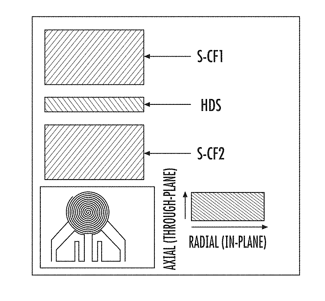
[0013] FIG. 1 is a schematic diagram showing thermal conductivity test using a Hot Disk TPS 2500.
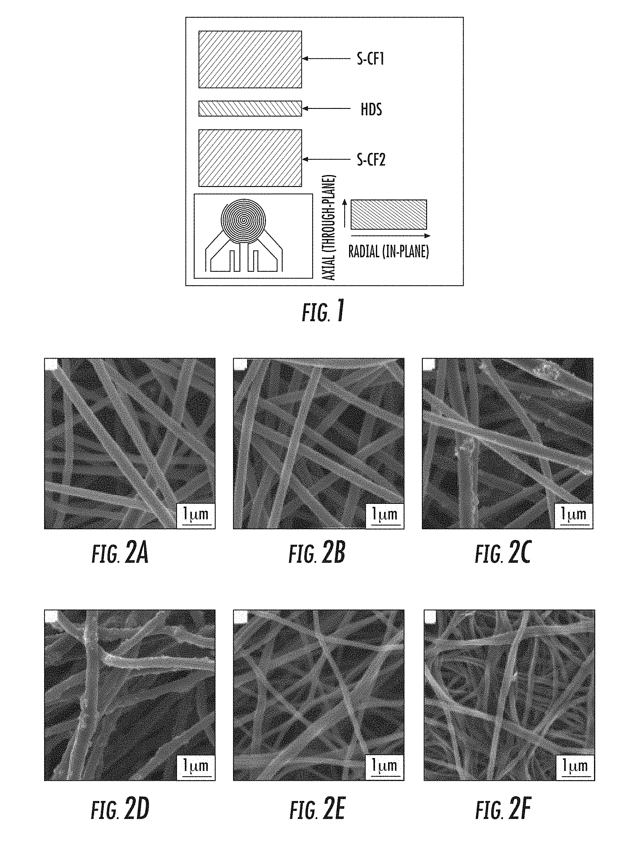
[0014] FIG. 2A is a scanning electron microscopy (`SEM`) image of ECNFs prepared from polyacrylonitrile (`PAN`) carbonized at 1200.degree. C.;
[0015] FIG. 2B is an SEM image of ECNFs prepared from PAN carbonized at 900.degree. C.;
[0016] FIG. 2C is an SEM image of ECNFs prepared from a spin dope comprising PAN with 5 wt. % SiO.sub.2 nanoparticles (`SiO.sub.2 NPs`) carbonized at 900.degree. C.;
[0017] FIG. 2D is an SEM image of ECNFs prepared from a spin dope comprising PAN with 10 wt % SiO.sub.2 NPs carbonized at 900.degree. C.;
[0018] FIG. 2E is an SEM image of ECNFs prepared from a spin dope comprising a 70/30 mixture of PAN and poly(methyl methacrylate) (`PMMA`): PAN/PMMA (70/30) carbonized at 900.degree. C.;
[0019] FIG. 2F is an SEM image of ECNFs prepared from a spin dope comprising PAN/PMMA (50/50) carbonized at 900.degree. C.
[0020] FIG. 3A is an SEM image of a cross-section of ECNFs carbonized at 900.degree. C.;
[0021] FIG. 3B is an SEM image of a cross-section of ECNFs with 10 wt % SiO.sub.2 NPs carbonized at 900.degree. C.
[0022] FIG. 4A is a transmission electron microscopy (`TEM`) image of ECNFs prepared from PAN and carbonized at 900.degree. C.;
[0023] FIG. 4B is a TEM image of ECNFs prepared from PAN with 10 wt. % SiO.sub.2 NPs and carbonized at 900.degree. C.;
[0024] FIG. 4C is a TEM image of ECNFs prepared from a spin dope comprising PAN/PMMA (70/30) and carbonized at 900.degree. C.;
[0025] FIG. 4D is a TEM image of ECNFs prepared from a spin dope comprising PAN/PMMA (70/30) with 10 wt. % SiO.sub.2 NPs and carbonized at 900.degree. C.;
[0026] FIG. 4E is a TEM image of ECNFs prepared from a spin dope comprising PAN/PMMA (50/50) and carbonized at 900.degree. C.;
[0027] FIG. 4F is a TEM image of ECNFs prepared from a spin dope comprising PAN/PMMA (50/50) with 10 wt. % SiO.sub.2 NPs and carbonized at 900.degree. C.
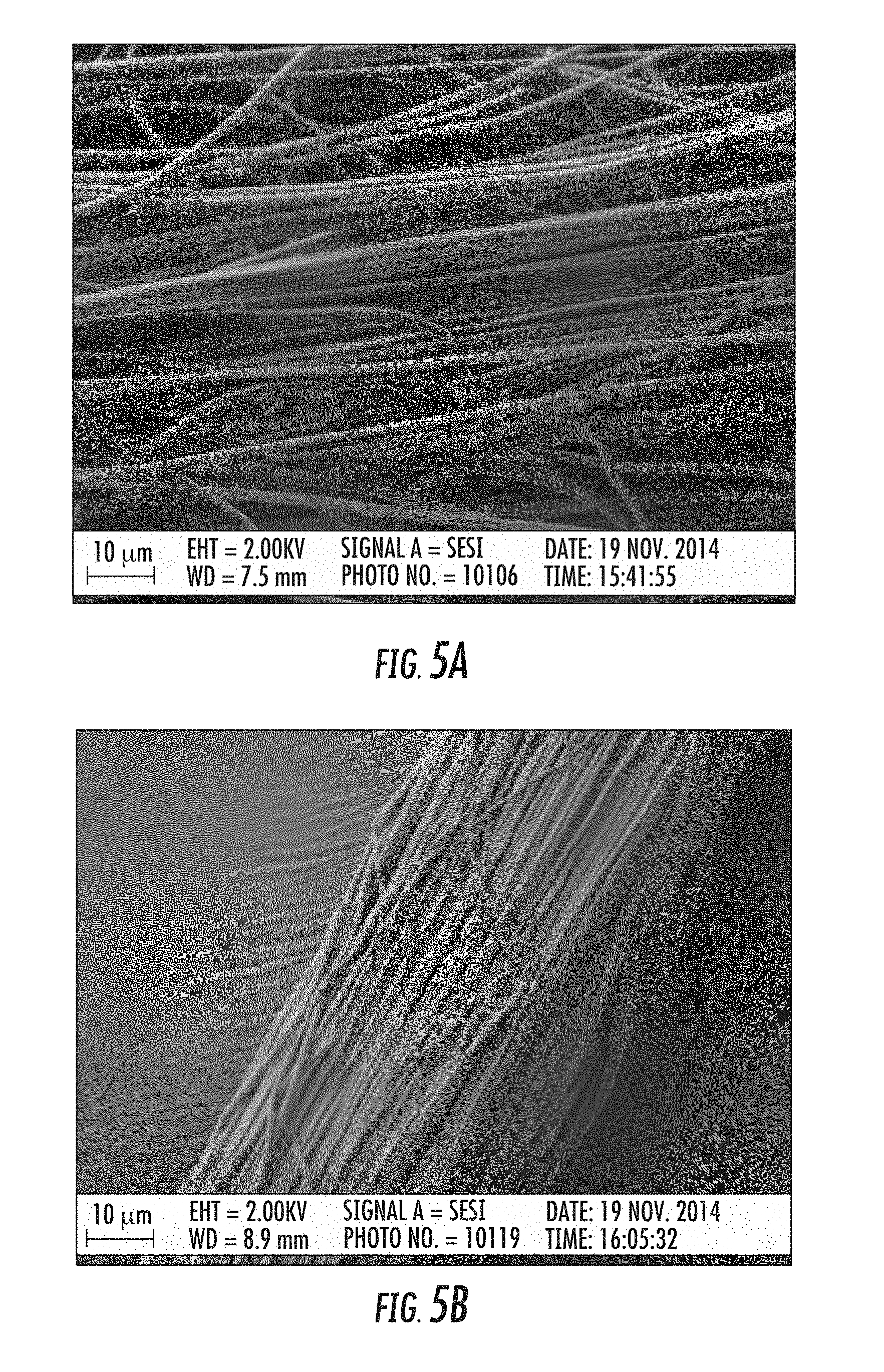
[0028] FIG. 5A is an SEM image of PAN nanofiber yarns as collected after electrospinning into a water bath;
[0029] FIG. 5B is an SEM image of PAN nanofiber stretched according to the methods disclosed herein;
[0030] FIG. 5C is an SEM image of nanofibers stabilized according to the methods disclosed herein; and
[0031] FIG. 5D is an SEM image of nanofibers carbonized according to the methods disclosed herein.
DETAILED DESCRIPTION
[0032] The presently disclosed subject matter will now be described more fully. The presently disclosed subject matter can, however, be embodied in different forms and should not be construed as limited to the embodiments set forth herein below and in the accompanying Examples. Rather, these embodiments are provided so that this disclosure will be thorough and complete, and will fully convey the scope of the embodiments to those skilled in the art.
[0033] All references listed herein, including but not limited to all patents, patent applications and publications thereof, and scientific journal articles, are incorporated herein by reference in their entireties to the extent that they supplement, explain, provide a background for, or teach methodology, techniques, and/or compositions employed herein.
Definitions
[0034] While the following terms are believed to be well understood by one of ordinary skill in the art, the following definitions are set forth to facilitate explanation of the presently disclosed subject matter.
[0035] Unless defined otherwise, all technical and scientific terms used herein have the same meaning as commonly understood to one of ordinary skill in the art to which the presently disclosed subject matter belongs.
[0036] Following long-standing patent law convention, the terms "a", "an", and "the" refer to "one or more" when used in this application, including the claims.
[0037] The term "and/or" when used in describing two or more items or conditions, refers to situations where all named items or conditions are present or applicable, or to situations wherein only one (or less than all) of the items or conditions is present or applicable.
[0038] The use of the term "or" in the claims is used to mean "and/or" unless explicitly indicated to refer to alternatives only or the alternatives are mutually exclusive, although the disclosure supports a definition that refers to only alternatives and "and/or."
[0039] As used herein "another" can mean at least a second or more.
[0040] As used herein, the term "about", when referring to a value is meant to encompass variations of in one example .+-.20% or .+-.10%, in another example .+-.5%, in another example .+-.1%, and in still another example .+-.0.1% from the specified amount, as such variations are appropriate to perform the disclosed methods. Accordingly, unless indicated to the contrary, the numerical parameters set forth in this specification and attached claims are approximations that can vary depending upon the desired properties sought to be obtained by the presently disclosed subject matter.
[0041] As used herein, "spin dope" refers to a fluid to be electrospun as disclosed herein. When the spin dope comprises a first polymer and a solvent, electrospinning is referred to as solution electrospinning. Typically the spin dope solvent is dimethylformamide (`DMF`), but other appropriate solvents are well-known to those of skill in the art. In some examples, the spin dope does not include a solvent and is used in a process referred to as "melt electrospinning."
[0042] Generally, the spin dope comprises a first polymer which is a carbon precursor, (e.g. a polymer that upon carbonization yields a substantially pure carbon material). Such carbon precursors include, but are not limited to polyacrylonitrile (PAN), polyvinyl alcohol (PVA), and pitch. Often, the spin dope comprises a second polymer, which decomposes significantly (e.g. more than about 50%, more than about 75%, more than about 90% or more than about 95%) during the disclosed carbonization process. The most commonly employed second polymer is poly(methyl methacrylate) (PMMA), but other polymers can have the disclosed characteristics of the second polymer.
[0043] As disclosed herein, the ratio of the first carbon-containing polymer to the second polymer in the spin dope can vary. Using PAN as representative of the first polymer and PMMA as the second polymer: the ratio of PAN to PMMA by weight ("PAN/PMMA") in the spin dope can vary. In one variation, the spin dope comprises 100% PAN. Alternately, the ratio is 80/20 PAN/PMMA or 70/30 PAN/PMMA. In another variation, the ratio is 50/50 PAN/PMMA. Usually the ratio comprises at least 50% PAN, for example a ratio of 55/45, 60/40, 65/35, 70/30, 75/25, 80/20, 85/15, 90/10 or 95/5 PAN/PMMA. The pore structure, including the degree of porosity, in the electrospun carbon nanofiber can vary based on the proportion of the second polymer. Larger relative amounts of the second (decomposing) polymer typically lead to larger pores.
[0044] As used herein "inert atmosphere" refers generally to an inert gas, such as nitrogen, argon, helium, neon, or the like, or a combination thereof, or may refer to any other gas, as long as the gas is not chemically reactive with the electrospun fibers or the nanofibers described herein.
[0045] As used herein, "stabilization" refers to heat treatment of the polymer nanofibers between about 100.degree. C. and about 400.degree. C., typically in the range of about 200.degree. C. to about 300.degree. C., with a heating rate of up to about 2.degree. C./min, or between about 0.5.degree. C./min and about 2.degree. C./min, in an oxygen-containing atmosphere (e.g. air). Without being bound by theory, the heat stabilization is generally thought to crosslink the carbon-containing molecules so that they can survive higher temperature carbonization without melting and/or decomposing
[0046] As used herein, the term "carbonization," "carbonized," or "carbonize" refers to heat treatment of the stabilized nanofibers described above, wherein carbonization temperature is typically no higher than about 1000.degree. C., or generally between about 600.degree. C. to about 1000.degree. C., alternately from about 700.degree. C. to about 900.degree. C. In some embodiments, the carbonization temperature is reached via a heating rate of up to about 10.degree. C./min, generally in an inert atmosphere, such as for example, argon, or under a vacuum. Alternately, the carbonization temperature can be reached using a heating rate of up to 5.degree. C./min or at a rate between about 5.degree. C./min and 10.degree. C./min. In some variations, the carbonization temperature is no more than 600.degree. C., no more than 700.degree. C., no more than about 800.degree. C., no more than about 900.degree. C., or no more than about 1000.degree. C.
[0047] As used herein, "carbon nanofibers" refers to carbon fibers with diameters from about 10 nm to about 1000 nm. The electrospun carbon nanofibers (`ECNF`) described herein result from heat treatment of polymer nanofibers, wherein the resulting carbon nanofibers have a cylindrical shape and relatively high specific surface area. When a spin dope comprises a combination of two polymers, such as a first polymer, PAN, and a second polymer, PMMA, the PMMA component can be removed via thermal decomposition during the carbonization processes and the resulting carbon nanofiber will have particular properties as outlined herein. When a spin dope comprises nanoparticles and the spin dope is electrospun into nanofibers, the nanoparticles are not displaced by the heat treatment nor thermally decomposed during the carbonization process, but as shown herein, remain a component part of the resulting modified ECNFs. The nanoparticles can be found on the surface of the nanofibers, as well as incorporated into the nanofibers themselves.
[0048] As used herein, "nanoparticles" refers to mostly spherical particles having an average diameter of less than about 1000 nm. Generally, nanoparticles have an average diameter of less than about 750 nm, less than about 500 nm, less than about 250 nm, less than about 100 nm, less than about 25 nm, less than about 12 nm, or even less than about 7 nm. Alternately, the nanoparticles can have an average diameter of between about 5 and about 15 nm, between about 15 nm and 50 nm, between about 100 nm and 300 nm, or between about 10 nm and 500 nm. "Low thermal conductivity" when used to describe nanoparticles generally refers to nanoparticles having thermal conductivity lower than 10 W/m K. Generally low thermal conductivity nanoparticles have a thermal conductivity lower than about 7.5 W/m K, lower than about 5 W/m K, lower than about 2.5 W/m K or lower than about 2 W/m K, or even lower than about 1 W/m K. Nanoparticles used in the methods and compositions disclosed herein generally includes nanoparticles that are stable during carbonization (that is, have a decomposition temperature well above the carbonization temperature) and have low thermal conductivity, as disclosed above. In some embodiments, the nanoparticles having a boiling point above about 1400.degree. C. Such nanoparticles can include, but are not limited to silica (SiO.sub.2) nanoparticles, calcium silicate (Ca.sub.2SiO.sub.4) nanoparticles, and clay nanoparticles.
[0049] "Multi-scale porous" such as when used in combination with a material, e.g. "multiscale porous material," or "multiscale porous nanofiber mat," refers to a material or mat having pores having average pore widths of different scales, such as two or more of the following: nanometer-sized, sub-micrometer-sized, and micrometer-sized pores. Micrometer-sized pores generally arise from inter-fiber pores (pores formed between nanofibers) and have an average pore width above 1 micron (.mu.m). In some embodiments, the micrometer-sized pores can have an average pore width of between about 1 .mu.m and about 25 .mu.m; alternately, between about 1 .mu.m and about 10 .mu.m, between about 2 .mu.m and about 8 .mu.m, or between about 1 .mu.m and about 5 .mu.m. Sub-micrometer pores generally have an average pore width between about 100 nm and 1000 nm, or between about 100 nm and about 750 nm, or between about 100 nm and about 500 nm. Pores of nanometer scale are typically less than about 100 nm, generally between about 1 nm and 100 nm, or between about 1 nm and about 75 nm, or between about 1 nm and about 50 nm, or between about 1 nm and about 25 nm, or between about 1 nm and about 15 nm. In some variations, the micrometer-sized pores can have an average width of no more than about 16 .mu.m, no more than about 14 .mu.m, no more than about 12 .mu.m, no more than about 10 .mu.m, no more than about 9 .mu.m, no more than about 8 .mu.m, no more than about 7 .mu.m, no more than about 6 .mu.m, no more than about 5 .mu.m, no more than about 4 .mu.m, no more than about 3 .mu.m no more than about 2 .mu.m, or no more than about 1 .mu.m. In some variations, the sub-micrometer-sized pores can have an average width of no more than about 1000 nm, or no more than about 900 nm, or no more than about 800 nm, or no more than about 700 nm, or no more than about 600 nm, or no more than about 500 nm, or no more than about 400 nm, or no more than about 300 nm, or no more than about 200 nm. In some variations, the nanometer-sized pores can have an average width of no more than about 100 nm, or no more than about 90 nm, or no more than about 80 nm, or no more than about 70 nm, or no more than about 60 nm, or no more than about 50 nm, or no more than about 40 nm, or no more than about 30 nm, or no more than about 20 nm.
[0050] As used herein "silica nanoparticles" or "SiO.sub.2 NPs" refer to particles comprising or consisting essentially of SiO.sub.2 (MW 60.08). Silica nanoparticles can be found in a variety of particle sizes (and corresponding surface areas). Representative sizes include, but are not limited to particle size: average particle size: 7 nm, surface area: 370-420 m.sup.2/g, (ii) average particle size: 12 nm, surface area: 175-225 m.sup.2/g, and (iii) 5-15 nm, surface area: 590-690 m.sup.2/g. Alternate sizes of nanoparticles or combinations of the nanoparticles disclosed herein can similarly be used in the methods disclosed herein.
[0051] As used herein "thermal conductivity" refers to the property of a material to conduct heat. It is commonly measured through transient plane source (TPS) method (see e.g. Log, T., and S. E. Gustafsson. "Transient plane source (TPS) technique for measuring thermal transport properties of building materials." Fire and materials 19.1 (1995): 43-49). "Low" thermal conductivity generally refers to compositions having thermal conductivity lower than 10 W/m K, lower than about 8 W/m K, lower than about 5 W/m K, lower than about 2.5 W/m K, or lower than about 2 W/m K, or lower than about 1 W/m K, or even lower than about 0.5 W/m K.
[0052] Thermal conductivity measurements of carbon fibers disclosed herein generally show that an increase in the heat treatment temperature corresponds to an increase in the thermal conductivity of the resulting carbon nanofibers. Due to structural characteristics at both the microscale and nanoscale, the thermal conductivity of a material can be affected by its porosity, at least in part due to phonon scattering, a mechanism of heat conduction in carbonaceous materials. Thermal conductivity generally decreases with increasing porosity.
[0053] As shown herein, low thermal conductivity carbon materials have been prepared from electrospinning. Electrospinning a polymer-containing spin dope yields a non-woven nanofibrous mat with micrometer scale inter-fiber pores. Sub-micrometer and nanometer pores can be introduced, according to the methods of the present application, with the addition to the spin dope of a second polymer and/or nanoparticles. Multiscale porous structures are disclosed herein; the presence of only one set (micrometer scale, sub-micrometer scale, or nanometer scale) of pores do not lead to the same improved properties reported herein. According to the methods disclosed herein, produced products have a distribution of pores across two or more scales, e.g. micrometer and sub-micrometer, micrometer and nanometer, sub-micrometer and nanometer, or have a distribution of pores across all three scales: micrometer, sub-micrometer and nanometer.
[0054] One factor influencing the size of the multiscale pores prepared according to the methods disclosed herein is the diameter of the electrospun nanofibers themselves, both before and after carbonization. In particular, the sub-micrometer and nanometer pore domains, the sources of which are typically the removal of the second polymer during carbonization and the presence of nanoparticles incorporated into the nanofibers or onto the nanofiber surfaces, are constrained by the size of the nanofibers themselves. Generally, carbon nanofibers prepared from a mixed polymer system have diameters of between about 400 nm and about 600 nm and have sub-micrometer pores of between about 100 nm and about 500 nm. As disclosed herein, a sub-micrometer scale carbon porous structure was prepared by addition of varying amounts of the second polymer. Smaller diameter carbon nanofibers typically have smaller sub-micrometer pores, while carbon nanofibers with larger diameters will typically have sub-micrometer pores that are larger.
[0055] The methods disclosed herein include, but are not limited to: (a) electrospinning a spin dope comprising a carbon precursor and a second polymer that decomposes during carbonization; and controlled carbonization of to yield a micrometer scale inter-fiber porous structure of electrospun carbon nanofiber; optionally nanoparticles are included in the spin dope. Exemplifying of such methods, varying ratios of poly(methyl methacrylate) (PMMA) were added to a PAN-containing spin dope. SiO.sub.2 NPs (thermal conductivity .about.1.5 W/m K) were used as a representative nanoparticulate insulator additive. According to the methods disclosed herein, a carbon nano-fibrous material having a multi-scale porous structure with thermal conductivity as low as 0.15 W/m K was prepared.
[0056] In one aspect, the present application discloses a method of preparing a multi-scale porous carbon-containing material, having a thermal conductivity of less than about 5 W/m K, the method comprising: (a) electrospinning a spin dope comprising a first polymer that is a carbon precursor; and further comprising: (i) a second polymer having a decomposition temperature lower than about 600.degree. C.; and/or (ii) nanoparticles having a boiling point above about 1400.degree. C. and a thermal conductivity of less than about 10 W/m K; wherein said electrospinning yields a polymer nanofiber; and (b) carbonizing a stabilized nanofiber at no more than about 1000.degree. C. In another aspect, the present application discloses a method of preparing a multi-scale porous carbon-containing material, having a thermal conductivity of less than about 4 W/m K, the method comprising: (a) electrospinning a spin dope comprising a first polymer that is a carbon precursor; a second polymer having a decomposition temperature lower than about 600.degree. C.; and nanoparticles having a boiling point above about 1400.degree. C. and a thermal conductivity of less than about 5 W/m K; wherein said electrospinning yields a polymer nanofiber; (b) stabilizing said polymer nanofiber; and (c) carbonizing said stabilized nanofiber at no more than about 1000.degree. C.
[0057] In one embodiment, the multi-scale porous carbon-containing material comprises an electrospun carbon nanofiber and has: (a) pores having an average pore width between about 1 .mu.m and about 10 .mu.m; (b) pores having an average pore width between about 100 nm and about 1000 nm; and/or (c) pores having an average pore width between about 1 nm and about 100 nm. In another embodiment, the material comprises an electrospun carbon nanofiber and has: (a) pores having an average pore width between about 1 .mu.m and about 10 .mu.m; (b) pores having an average pore width between about 100 nm and about 1000 nm; and (c) pores having an average pore width between about 1 nm and about 100 nm. In yet another embodiment, the fibrous material has (a) pores having an average pore width between about 1 .mu.m and about 5 .mu.m; (b) pores having an average pore width between about 100 nm and about 500 nm; and (c) pores having an average pore width between about 1 nm and about 75 nm. In yet another embodiment, the fibrous material has (a) pores having an average pore width between about 1 .mu.m and about 5 .mu.m; (b) pores having an average pore width between about 100 nm and about 200 nm; and (c) pores having an average pore width between about 1 nm and about 25 nm.
[0058] In one variation of any aspect or embodiment, the multi-scale porous carbon-containing material disclosed herein has a thermal conductivity of less than about 10 W/m K. In another variation of any aspect or embodiment, the multi-scale porous carbon-containing material disclosed herein has a thermal conductivity of less than about 5 W/m K; less than about 4 W/m K, less than about 3 W/m K, less than about 2 W/m K, less than about 1 W/m K, less than about 0.5 W/m K, or less than about 0.25 W/m K, or even less than about 0.2 W/m K.
[0059] In one variation of any aspect or embodiment disclosed herein, the first polymer is polyacrylonitrile (PAN). In another variation, the first polymer is polyvinyl alcohol (PVA). In one embodiment, the second polymer has a decomposition temperature below about 500.degree. C. In one variation of any aspect or embodiment, the second polymer in the bicomponent polymer system is poly(methyl methacrylate).
[0060] In one embodiment, the ratio of the first polymer to the second polymer is 90:10 or 80:20 or 70/30 or 60:40 or 50:50. Usually the ratio comprises at least 50% of the first polymer, for example a ratio of 55:45, 60:40, 65:35, 70:30, 75:25, 80:20, 85:15, 90:10 or 95:5 first polymer:second polymer. In one variation, the ratio of polyacrylonitrile to poly(methyl methacrylate) is between about 80:20 and about 50:50; alternately the ratio of PAN to PMMA is between about 70:30 and about 50:50. In another variation, the ratio of polyvinyl alcohol to poly(methyl methacrylate) is between about 80:20 and about 50:50; alternately the ratio of PVA to PMMA is between about 70:30 and about 50:50.
[0061] In one variation of any aspect or embodiment disclosed herein, nanoparticles disclosed in the methods and compositions herein have a boiling point above about 1400.degree. C. and a thermal conductivity of less than about 7.5 W/m K. In another variation, the nanoparticles have a thermal conductivity of less than about 5 W/m K or less than about 2.5 W/m K. In one variation, the nanoparticles comprise silicon dioxide. In another variation, the nanoparticles comprise calcium silicate. In another variation, the nanoparticles comprise nanoclay.
[0062] In one variation of any aspect or embodiment disclosed herein, nanoparticles disclosed in the methods comprise at least about 2.5 wt % of the spin dope relative to the weight of the first polymer. In another variation, the nanoparticles comprise at least about 5 wt % of the spin dope relative to the weight of first polymer; alternately, the nanoparticles comprise at least about 10 wt % of the spin dope relative to the weight of the first polymer or at least about 20 wt % of the spin dope relative to the weight of the first polymer. In another variation, nanoparticles in the fibrous compositions disclosed herein comprise at least about 5 wt % of the carbonized nanofiber. In another variation, nanoparticles comprise at least about 10 wt % of the carbonized nanofiber, or at least about 20 wt % of the carbonized nanofiber, or even at least about 40 wt % of the carbonized nanofiber. In one embodiment of the methods disclosed herein, heat treating the electrospun polymer nanofibers comprises heating to a stabilization temperature between about 220.degree. C. and about 300.degree. C. and holding at the stabilization temperature for sufficient time to yield a stabilized nanofiber; and then heating the stabilized nanofiber to a carbonization temperature of no more than about 1000.degree. C. and holding at said carbonization temperature for at least about 30 minutes. In one variation, the stabilizing temperature is between about 250.degree. C. and about 290.degree. C. and the sufficient time is at least about 30 minutes, at least about 1 hour, at least about 2 hours, at least about 3 hours, or at least about 4 hours. In another variation, the stabilizing temperature is about 280.degree. C. and the sufficient time is at least about 30 minutes, at least about 1 hour, at least about 2 hours, at least about 3 hours, or at least about 4 hours. In one variation, the carbonization temperature is no more than about 950.degree. C., or no more than about 900.degree. C., no more than about 850.degree. C., no more than about 800.degree. C., no more than about 750.degree. C. Alternately, the carbonization temperature is at least about 600.degree. C., at least about 650.degree. C., at least about 700.degree. C., at least about 750.degree. C., at least about 800.degree. C., at least about 850.degree. C., at least about 900.degree. C., at least about 950.degree. C., or at least about 1000.degree. C. In one variation, the carbonization temperature is held for at least about 30 minutes, at least about 1 hour, at least about 2 hours, at least about 3 hours, at least about 4 hours, at least about 5 hours, at least about 6 hours, at least about 7 hours, at least about 8 hours, at least about 9 hours, or at least about 10 hours.
[0063] In one aspect disclosed herein is a nanofibrous carbon product having a thermal conductivity of no more than about 5 W/m K, comprising nanoparticles wherein the nanoparticles have a boiling point above about 1400.degree. C. and a thermal conductivity of less than about 10 W/m K. In one embodiment, the nanofibrous carbon product comprises (a) pores having an average pore width between about 1 .mu.m and about 10 .mu.m; (b) pores having an average pore width between about 100 nm and about 1000 nm; and/or (c) pores having an average pore width between about 1 nm and about 100 nm. In another embodiment, the nanofibrous carbon product comprises electrospun carbon nanofibers and has: (a) pores having an average pore width between about 1 .mu.m and about 10 .mu.m; (b) pores having an average pore width between about 100 nm and about 1000 nm; and (c) pores having an average pore width between about 1 nm and about 100 nm. In yet another embodiment, the nanofibrous carbon product has (a) pores having an average pore width between about 1 .mu.m and about 5 .mu.m; (b) pores having an average pore width between about 100 nm and about 500 nm; and (c) pores having an average pore width between about 1 nm and about 75 nm. In yet another embodiment, the nanofibrous carbon product has (a) pores having an average pore width between about 1 .mu.m and about 5 .mu.m; (b) pores having an average pore width between about 100 nm and about 200 nm; and (c) pores having an average pore width between about 1 nm and about 50 nm. In one variation, the nanoparticles comprise silicon dioxide. In another variation, the nanoparticles comprise calcium silicate. In one variation, the nanofibrous carbon product comprises electrospun carbon nanofibers. In one variation, the nanofibrous carbon product has a thermal conductivity of no more than about 2 W/m K, no more than about 1 W/m K, no more than about 0.5 W/m K, no more than about 0.25 W/m K or no more than about 0.20 W/m K.
[0064] In another aspect, the present application discloses a thermal insulating material comprising a nanofibrous carbon product described herein.
[0065] In some embodiments, the polymer nanofibers are prepared by electrospinning a spin dope. In some embodiments, the electrospinning is solution electrospinning. In some embodiments, the electrospinning is melt electrospinning.
[0066] As disclosed herein, the electrospun polymer nanofibers are stabilized, or heated in an oxygen-containing atmosphere using a heating rate of no more than about 5.degree. C. per minute, or alternately between about 0.5.degree. C. per minute and 2.0.degree. C. per minute to a stabilization temperature of at least about 200.degree. C. In one variation the stabilization temperature is held for at least about 1 hour to yield stabilized nanofibers. In some embodiments, the heating rate to the stabilization temperature is about 0.75.degree. C./min to about 1.75.degree. C./min, or about 1.degree. C./min to about 1.5.degree. C./min. In some embodiments, the stabilization temperature is at least about 210.degree. C., at least about 220.degree. C., at least about 230.degree. C., at least about 240.degree. C., at least about 250.degree. C., at least about 260.degree. C., at least about 270.degree. C., at least about 280.degree. C., at least about 290.degree. C., or at least about 300.degree. C. In some embodiments, the stabilization temperature is between about 220.degree. C. and about 300.degree. C. or between about 250.degree. C. and about 290.degree. C., or the stabilization temperature is about 280.degree. C. The polymer nanofibers are held at the stabilization temperature for at least about 30 minutes, at least about 1 hour, at least about 2 hours, at least about 3 hours, at least about 4 hours, at least about 5 hours, or at least about 6 hours. Alternately the nanofibers are held at the stabilization temperature for between about 1 hour and about 10 hours, or between about 2 and about 9 hours, or between about 4 and about 7 hours, or held for about 5 hours to yield a stabilized nanofiber.
[0067] As disclosed herein, the stabilized nanofibers can be cooled to room temperature. Alternately, the stabilized nanofibers can be directly subjected to heating for carbonization.
[0068] As disclosed herein, the stabilized nanofibers are carbonized, or heated in an inert atmosphere using a heating rate of between about 1.degree. C. per minute and 15.degree. C. per minute to a carbonization temperature of no more than about 1000.degree. C. and held there for at least about 0.5 hours to yield carbonized nanofibers. In some embodiments, the heating rate to the carbonization temperature is about 2.degree. C./min to about 15.degree. C./min, or about 2.degree. C./min-12.5.degree. C./min, or about 2.degree. C./min-10.degree. C./min, or about 5.degree. C./min-10.degree. C./min, or is about 10.degree. C./min, or about 9.degree. C./min, or about 8.degree. C./min, or about 7.degree. C./min, or about 6.degree. C./min, or about 5.degree. C./min, or about 4.degree. C./min. In some embodiments, the carbonization temperature is about 700.degree. C-1000.degree. C. or about 750.degree. C-950.degree. C., or is about 800.degree. C-900.degree. C. In some embodiments, the carbonization temperature is at least about 600.degree. C., or at least about 700.degree. C., or at least about 800.degree. C., or at least about 900.degree. C. In some embodiments, the carbonization time is at least about 30 minutes; at least about 1 hour, at least about 2 hours, at least about 3 hours, at least about 4 hours, at least about 5 hours, or at least about 6 hours. In some embodiments the carbonization time is about 0.5-5 hrs, or about 1-4 hrs, or about 1-3 hrs.
[0069] In some embodiments, a carbon nanofiber mat of the present application has a multi-scale porous structure, a thermal conductivity below about 4 W/m K, an average nanofiber diameter of between about 200 nm and about 900 nm; and (a) a specific surface area of at least about 30 m.sup.2/g as measured by BET (Brunauer-Emmett-Teller) isotherm and/or (b) a total pore volume of at least about 0.13 cm.sup.3/g as measured by N.sub.2 gas sorption. In other embodiments, a carbon nanofiber mat of the present application has a multi-scale porous structure, a thermal conductivity below about 4 W/m K, an average nanofiber diameter of between about 300 nm and about 700 nm; and (a) a specific surface area of at least about 45 m.sup.2/g as measured by BET isotherm and/or (b) a total pore volume of at least about 0.17 cm.sup.3/g as measured by N.sub.2 gas sorption. In other embodiments a carbon nanofiber mat of the present application has a multi-scale porous structure, a thermal conductivity below about 2 W/m K, an average nanofiber diameter of between about 400 nm and about 600 nm; and (a) a specific surface area of at least about 50 m.sup.2/g as measured by BET isotherm and/or (b) a total pore volume of at least about 0.17 cm.sup.3/g as measured by N.sub.2 gas sorption. In some embodiments, the nanoparticles comprise silicon dioxide; in other embodiments, the nanoparticles comprise calcium silicate. In another embodiment, the present application discloses a thermal insulating material comprising a carbon nanofiber mat having a multi-scale porous structure as disclosed herein.
EXAMPLES
[0070] The following Examples have been included to provide guidance to one of ordinary skill in the art for practicing representative embodiments of the presently disclosed subject matter. In light of the present disclosure and the general level of skill in the art, those of skill can appreciate that the following Examples are intended to be exemplary only and that numerous changes, modifications, and alterations can be employed without departing from the scope of the presently disclosed subject matter.
Materials
[0071] Each of the following were purchased from Sigma-Aldrich (St. Louis, Mo.): Polyacrylonitrile (PAN, average molecular weight Mw=150,000, catalog #181315), Poly(methyl methacrylate) (PMMA, average molecular weight Mw=120,000, catalog #182230), three different types of silicon dioxide nanoparticles (SiO.sub.2, molecular weight Mw=60.08): (i) particle size: 7 nm, surface area: 370-420 m.sup.2/g, catalog #S5130; (ii) average particle size: 12 nm, surface area: 175-225 m.sup.2/g, catalog #718483; and (iii) particle size: 5-15 nm, surface area: 590-690 m.sup.2/g, catalog #637246, and N,N-Dimethylformamide (DMF, catalog #227056). The chemicals were used as received without further purification.
Example 1
CF and ECNF optionally with SiO.sub.2 NP
Spin Dope Preparation
[0072] The targeted polymers were dissolved in DMF to prepare 9 wt. % solutions for spinning. For those spin dopes containing SiO.sub.2 nanoparticles (SiO.sub.2 NPs, average particle size 12 nm), SiO.sub.2 NPs were first added to DMF and the suspension was sonicated for 20 min; then the solution containing SiO.sub.2 NPs was mixed with the disclosed polymer solution under constant stirring followed by sonication for another 10 minutes to break up any aggregates of the SiO.sub.2 NPs and ensure even distribution of SiO.sub.2 NPs within the solution before electrospinning (Refer to Table 1). The amount of SiO.sub.2 NPs was determined relative to the mass of PAN used in the spin dope. As shown in Table 1, examples of 5 wt % SiO.sub.2 NP relative to the amount of PAN and 10 wt % SiO.sub.2 NP relative to the amount of PAN were used.
TABLE-US-00001 TABLE 1 Preparative spin dopes Product name Preparative spin dope ECNFs 9 wt % PAN in DMF ECNFs with 5 wt % SiO.sub.2 9 wt % PAN + NPs 2.5 (wt % of PAN) SiO.sub.2 in DMF ECNFs with 10 wt % SiO.sub.2 9 wt % PAN + NPs 5 (wt % of PAN) SiO.sub.2 in DMF ECNFs from electrospinning 9 wt % PAN/PMMA (mass ratio: 70/30) PAN/PMMA (70/30) in DMF ECNFs from electrospinning 9 wt % PAN/PMMA (mass ratio: 50/50) PAN/PMMA (50/50) in DMF ECNFs with 5 wt % SiO.sub.2 9 wt % PAN/PMMA (mass ratio: 70/30) + NPs from electrospinning 2.5 (wt % of PAN) SiO.sub.2 in DMF PAN/PMMA (70/30) ECNFs with 5 wt % SiO.sub.2 9 wt % PAN/PMMA (mass ratio: 50/50) + NPs from electrospinning 2.5 (wt % of PAN) SiO.sub.2 in DMF PAN/PMMA (50/50) ECNFs with 10 wt % SiO.sub.2 9 wt % PAN/PMMA (mass ratio: 70/30) + NPs from electrospinning 5 (wt % of PAN) SiO.sub.2 in DMF PAN/PMMA (70/30) ECNFs with 10 wt % SiO.sub.2 9 wt % PAN/PMMA (mass ratio: 50/50) + NPs from electrospinning 5 (wt % of PAN) SiO.sub.2 in DMF PAN/PMMA (50/50)
Electrospinning Nanofibers
[0073] The spinning solution was transferred to a 30 ml syringe fitted with a blunt 18-gauge stainless steel needle. Ultrafine fibers were electrospun from each spin dope at 15 kV and collected on a grounded aluminum foil 20 cm from the tip of the electrospinning syringe at a flow rate of 1 mL/hr maintained by a digital syringe pump. The resulting polymer fibrous mats were detached from the collector, dried at room temperature for at least 24 hr, and kept in a fume hood until needed for further analysis.
Polymer Film Preparation
[0074] Each of the polymer solutions identified in Table 1 was cast on Teflon plates at room temperature followed by drying in fume hood for at least 24 hr, to enable formation of a polymer film.
Stabilization and Carbonization
[0075] The nanofibrous polymer mats, as well as corresponding polymer films, were stacked between 6.times.6 inch graphite plates from Graphitestore.com and placed in a furnace (Carbolite HTF 18/8, Watertown, Wis.) for stabilization and carbonization. All samples were stabilized in air from room temperature to 280.degree. C. at a heating rate of 1.degree. C./min, then the temperature was held at 280.degree. C. for 6 hr. As an optional step, the stabilized samples were cooled to room temperature. After stabilization, the nanofibers were heated in a nitrogen atmosphere at a heating rate of 5.degree. C./min to a carbonization temperature of 900.degree. C. or 1200.degree. C.; the samples were allowed to dwell at the carbonization temperature for about an hour before the samples were cooled down to room temperature.
Characterization
[0076] The structure and morphology of the nanofibrous materials were examined under a scanning electron microscope (`SEM`) with an attached energy-dispersive X-ray spectrometer (`EDX`) (Carl Zeiss Auriga-BU FIB FESEM, Oberkochen, Germany) and a transmission electron microscope (`TEM,` Carl Zeiss Libra 120 Plus TEM, Oberkochen, Germany).
[0077] The pore volume and specific surface area of the prepared samples were each characterized by nitrogen adsorption using a surface area and porosity analyzer (Micromeritics, ASAP 2020, Norcross, Ga.). The orientation of graphitic planes in the carbonized nanofibers was characterized by an Agilent Oxford Gemini X-Ray Diffractometer (XRD, Oxfordshire. UK) using Cu K.alpha. (.lamda.=0.15418 nm) radiation over the 2.theta. range 20.degree.-40.degree.. The pore structure and structural conversions resulting from stabilization and carbonization and effect of porous nature were investigated by a HORIBA LabRAM ARAMIS Raman Spectrometer (Kyoto, Japan).
[0078] In-plane thermal conductivity of ECNFs nanofibrous materials and carbonized cast films was measured at room temperature using a HotDisk TPS 2500 (ThermTest Inc., Fredericton, Canada), shown schematically in FIG. 1. To measure thermal conductivity, square pieces S-CF1 and S-CF2 (30 mm.times.30 mm.times.0.3 mm) were cut from each electrospun carbon nanofiber (ECNF) mat or carbon film sample. A round Hotdisk Kapton sensor 7577 (ThermTest Inc., Fredericton, Canada) HDS with radius 2.001 mm was put in between two square pieces S-CF1 and S-CF2 with a radial probing depth of 10 mm. The two carbon pieces S-CF1 and S-CF2 with sensor HDS were then sandwiched between two Styrofoam films with just enough external force to secure but not damage the carbon pieces S-CF1 and S-CF2. The thermal conductivity was measured three times for each carbon sample S-CF1 and S-CF2.
Results and Discussion
[0079] SEM images of ECNFs nanofibrous mats clearly showed a microporous structure with randomly deposited carbon nanofibers at -400-500 nm scale and inter-fiber pores at micrometer scale at both carbonization temperatures (FIGS. 2A and 2B). These ECNFs have relatively uniform size and smooth surface without any microscopically identifiable particles and are basically solid fibers based on their cross-sectional SEM image (FIG. 3A) and TEM image (FIG. 4A).
[0080] Surface morphology, as well as the structure of ECNFs, was affected by addition of either SiO.sub.2 NPs or PMMA to the PAN spin dopes.
[0081] ECNFs prepared from SiO.sub.2 NP-doped PAN solution showed surface nanoparticle clusters (FIGS. 2C and 2D), confirming SiO.sub.2 NPs integration. The cross-sectional SEM image of a randomly identified nanofiber from this type ECNFs clearly showed that SiO.sub.2 NPs and/or their clusters exist on the nanofiber surface as well as inside the nanofiber. Nano-pores of between about 10 nm and about 90 nm were also observed on the nanofiber surface and inside ECNFs (FIG. 3B). The surface nanoparticle clusters, as well as nanoporous structure of the ECNF itself, was confirmed by TEM image (FIG. 4B). The density of SiO.sub.2 NPs on ECNFs surface can be controlled by adjusting the amount of SiO.sub.2 NPs that are added to the electrospinning solution.
[0082] The ECNFs resulting from PAN/PMMA bicomponent spin dope demonstrated a coarse surface morphology with narrow surface indents (FIGS. 2E and 2F), which may have been caused by PMMA burn-off during heat treatment and were confirmed by elongated light domains (voids) in TEM images (FIGS. 4C and 4E). The light domains in TEM indicated voids in individual ECNF and confirmed its nanoporous structure. These voids also indicate the location of previous PMMA domains in the PAN/PMMA bicomponent nanofibers before heat treatment. These voids became larger and merge into continuous channels along the length of nanofibers upon increasing PMMA content from 30% (PAN/PMMA=70/30) to 50% (PAN/PMMA=50/50). Phase-separated PMMA domains in the PAN/PMMA bicomponent precursor nanofibers decomposed completely at .about.370.degree. C. (during stabilization/carbonization), generating the submicroporous structure observed in the resultant ECNFs. As shown (FIGS. 4D and 4F), introducing SiO.sub.2 NPs to PAN/PMMA spin dopes also contributed to the nanoporous structure in the resultant ECNFs. Carbonization of PAN is a volume-shrinking process, as non-carbon elements are removed; this is especially true in the bicomponent system, from which PMMA is removed during stabilization/carbonization. Inclusion of SiO.sub.2 NPs in both the PAN and the PAN/PMMA systems resulted in nanoscale voids/pores in the final ECNFs, as the individual nanofiber volume shrinkage changed the location of SiO.sub.2 NPs.
[0083] XRD was employed to investigate crystalline structure of the prepared ECNFs. ECNFs showed diffraction peaks centered at 2.theta. angle 26-27.degree., attributed to the (002) crystallographic plane of graphite crystallites. An increase in intensity and sharpness of (002) peak was observed as the carbonization temperature increased from 900.degree. C. to 1200.degree. C. The XRD curves, in conjunction with the calculated results in Table 2 using the Scherrer equation, demonstrates that an increase in carbonization temperature (from 900.degree. C. to 1200.degree. C.) correlates with a growth of ordered carbon structure in both proportion and size, as well as a reduction of interplanar spacing. Stated another way, decreasing the carbonization temperature led to a growth of disordered carbon structure and a decrease in the size of graphite crystallites as well as an increase in the interplanar spacing. Based on the data summarized herein, addition of SiO.sub.2 NPs and introduction of PMMA to the PAN spin dope reduced graphite crystallite sizes and led to larger inter-planar distances in the product ECNF.
TABLE-US-00002 TABLE 2 The average interplanar spacing "d.sub.(002)" and lateral dimension of crystallites "L.sub.c" of ECNFs calculated from XRD results (all ECNF samples were carbonized at 900.degree. C. unless stated otherwise) 2.theta..sub.(002) .beta. d.sub.(002) L.sub.c Sample (.degree.) (radian) (.ANG.) (nm) ECNFs (1200.degree. C.) 26.5 0.0979 3.36 1.45 ECNFs (900.degree. C.) 26.4 0.1169 3.38 1.22 ECNFs with 10% SiO.sub.2 NPs 26.4 0.1392 3.38 1.02 ECNFs from electrospinning 26.4 0.7861 3.38 0.18 PAN/PMMA (70/30) ECNFs with 10% SiO.sub.2 NPs 26.3 0.7861 3.39 0.18 from electrospinning PAN/PMMA (70/30)
[0084] BET surface area results of the ECNF nanofibrous mats (Table 3) indicated that higher carbonization temperature led to smaller pore size and lower pore volume as well as lower BET specific surface area. Integration of SiO.sub.2 NPs led to larger pore size, higher pore volume and higher BET specific surface area. Increasing the SiO.sub.2 NPs content led to higher pore volume and higher BET specific surface area.
[0085] Inclusion of PMMA in the spin dopes yielded ECNFs with greater pore volume and a higher BET specific surface area while each of pore size, pore volume and BET specific surface area of ECNFs increased with increasing PMMA content. Without being bound by theory, the structural changes appear to be due to burning off PMMA during carbonization (PMMA decomposes to gaseous monomers at .about.370.degree. C.). Larger proportions of PMMA occupied more volume and formed larger phase domains in bicomponent PAN/PMMA nanofibers. Greater pore volume, larger pore size, and higher specific surface area were thus generated upon PMMA removal during carbonization. Integration of SiO.sub.2 NPs gave rise to greater pore volume and higher BET specific surface area. The pore size, however, is independent of amount of SiO.sub.2 NPs even at 10 wt % loading, consistent with TEM observations. The movement of SiO.sub.2 NPs due to fiber shrinkage in the process of carbonization resulted in voids whose sizes are dependent on SiO.sub.2 NP sizes regardless of SiO.sub.2 NP proportion in the ECNFs. Combination of PMMA and SiO.sub.2 NPs in spinning solution further increased pore volume and BET specific surface area of resultant ECNFs. The largest BET surface area of 55.14 m.sup.2/g was observed from the ECNFs containing 10 wt % SiO.sub.2 NPs that were electrospun from 50/50 PAN/PMMA spinning solution.
TABLE-US-00003 TABLE 3 Average pore width, pore volume and BET surface area of ECNFs (All samples were carbonized at 900.degree. C. unless otherwise stated) Average Pore BET Surface Pore Width Volume Area Sample (nm) (cm.sup.3/g) (m.sup.2/g) ECNFs (1200.degree. C.) 12.48 0.02 7.66 ECNFs (900.degree. C.) 16.11 0.03 10.65 ECNFs with 5 wt. % SiO.sub.2 18.88 0.07 15.61 NPs ECNFs with 10 wt. % SiO.sub.2 18.78 0.13 39.18 NPs ECNFs from electrospinning 16.11 0.13 31.81 PAN/PMMA (70:30) ECNFs from electrospinning 20.66 0.16 33.90 PAN/PMMA (50:50) ECNFs with 5 wt. % SiO.sub.2 15.63 0.17 45.15 NPs from electrospinning PAN/PMMA (70:30) ECNFs with 5 wt. % SiO.sub.2 18.58 0.18 49.02 NPs from electrospinning PAN/PMMA (50:50) ECNFs with 10 wt. % SiO.sub.2 17.57 0.18 54.21 NPs from electrospinning PAN/PMMA (70:30) ECNFs with 10 wt. % SiO.sub.2 20.09 0.19 55.14 NPs from electrospinning PAN/PMMA (50:50)
[0086] Raman spectra of ECNFs show two characteristic bands: "D-band" and "G-band." "D-band" is centered at .about.1340 cm.sup.-1 and is related to disordered turbostatic carbon structure which is attributed to breakdown of lattice symmetry of the graphitic cell. "D-band" is usually correlated to small crystal size and structural disorder that are visible in poorly graphitized fibers with a tendency to disappear at higher carbonization temperatures. "G-band" is centered at .about.1580 cm.sup..about.1 and is related to ordered graphitic structures. The positions of these two bands are independent of the carbonization temperature and the intensity ratio of the "D-band" to the "G-band" ((I.sub.D/I.sub.G, known as the "R-value") generally indicates the amount of structurally ordered graphite crystallites in the ECNFs. The R-values of the two bands were calculated (Table 4) and showed a decrease with increasing final carbonization temperature, suggesting that the disordered carbonaceous components were converted into more ordered graphite crystallites. Increasing the amount of SiO.sub.2 NPs and/or PMMA in spin dopes led to increased R-values of the product ECNFs, signifying an increase in the disorder of carbonaceous structure in the ECNFs, which is consistent with XRD results--crystallization of the component carbon is obstructed by PMMA removal and the presence of SiO.sub.2 NPs.
TABLE-US-00004 TABLE 4 I.sub.D/I.sub.G and R-value of ECNFs (Samples were carbonized at 900.degree. C. unless otherwise stated) I.sub.D/I.sub.G Sample I.sub.D I.sub.G (R-value) ECNFs (1200.degree. C.) 271.30 307.12 0.88 ECNFs (900.degree. C.) 961.05 1037.99 0.92 ECNFs with 10 wt. % SiO.sub.2 NPs 410.35 431.38 0.95 ECNFs from electrospinning 1681.52 1760.79 0.95 PAN/PMMA (70/30) ECNFs from electrospinning 1675.83 1722.41 0.97 PAN/PMMA (50/50) ECNFs with 10 wt. % SiO.sub.2 NPs 614.02 624.37 0.98 from electrospinning PAN/PMMA (70/30) ECNFs with 10 wt. % SiO.sub.2 NPs 828.96 835.61 0.99 from electrospinning PAN/PMMA (50/50)
[0087] Thermal conductivity results (Tables 5A and 5B) indicated that lower carbonization temperature corresponded to a decrease in the thermal conductivity of ECNFs. An ECNF mat prepared from carbonization at 1200.degree. C. possessed a thermal conductivity of --33 W/m K, even larger than regular carbon fibers. Reducing the carbonization temperature from 1200.degree. C. to 900.degree. C. reduced the corresponding thermal conductivity by more than a magnitude, to 2.5 W/m K, a value even lower than rayon-based carbon fibers (typically .about.4 W/m K).
[0088] To investigate the effect of inter-fiber microporosity on thermal conductivity of the ECNF mats, carbon films were cast from the spinning solutions and carbonized under the same condition as the ECNF mats (at 900.degree. C.). The carbon films showed similar trends in porosity and specific surface area as ECNFs after inclusion of PMMA and SiO.sub.2 NPs (Table 6). The porosity and specific surface area results confirmed smaller pore volume and lower specific surface area in carbon films compared to corresponding ECNF samples; higher thermal conductivities were observed for the carbon films. Compared to ECNF nanofibrous mats, the carbon films showed up to 18-fold higher thermal conductivities, suggesting that inter-fiber porosity of ECNF nanofibrous mats play an important role in lowering thermal conductivity. See Table 5A and 5B. The microporous carbon structure achieved through electrospinning nanofibers reduced thermal conductivity from 7.64 W/m K measured for a carbon film carbonized at 900.degree. C. down to 2.48 W/m K, a 67.5% reduction, for ECNF (900.degree. C.).
TABLE-US-00005 TABLE 5A Thermal conductivity of ECNFs (Samples were carbonized at 900.degree. C. unless otherwise stated) Thermal Conductivity Sample (W/m K) ECNFs (1200.degree. C.) 33.11 .+-. 0.57 ECNFs (900.degree. C.) 2.48 .+-. 0.08 ECNFs with 5 wt. % SiO.sub.2 NPs 1.70 .+-. 0.19 ECNFs with 10 wt. % SiO.sub.2 NPs 1.25 .+-. 0.05 ECNFs from electrospinning PAN/PMMA (70/30) 1.49 .+-. 0.14 ECNFs from electrospinning PAN/PMMA (50/50) 1.28 .+-. 0.08 ECNFs with 5 wt. % SiO.sub.2 NPs from electrospinning 1.15 .+-. 0.08 PAN/PMMA (70/30) ECNFs with 5 wt. % SiO.sub.2 NPs from electrospinning 0.87 .+-. 0.04 PAN/PMMA (50/50) ECNFs with 10 wt. % SiO.sub.2 NPs from electrospinning 0.38 .+-. 0.02 PAN/PMMA (70/30) ECNFs with 10 wt. % SiO.sub.2 NPs from electrospinning 0.15 .+-. 0.02 PAN/PMMA (50/50)
TABLE-US-00006 TABLE 5B Thermal conductivity of carbon films (`CF`) (Samples were carbonized at 900.degree. C.) Thermal Conductivity Sample (W/m K) CF (900.degree. C.) 7.64 .+-. 0.33 CF with 10 wt. % SiO.sub.2 NPs 4.41 .+-. 0.16 CF from PAN/PMMA (70/30) 5.05 .+-. 0.03 CF from PAN/PMMA (50/50) 4.87 .+-. 0.46 CF with 10 wt. % SiO.sub.2 NPs from PAN/PMMA (70/30) 2.89 .+-. 0.31 CF with 10 wt. % SiO.sub.2 NPs from PAN/PMMA (50/50) 2.72 .+-. 0.02
TABLE-US-00007 TABLE 6 Average pore width, pore volume and BET specific surface area of carbon films (CF) that were cast from spin dopes and carbonized at 900.degree. C. Average Pore BET Surface Pore Width Volume Area Sample (nm) (cm.sup.3/g) (m.sup.2/g) CF 15.09 0.02 4.43 CF with 10 wt. % SiO.sub.2 NPs 18.96 0.05 17.84 CF from PAN/PMMA (70/30) 15.62 0.08 10.04 CF from PAN/PMMA (50:50) 19.74 0.09 17.35 CF with 10 wt. % SiO.sub.2 NPs 16.26 0.11 18.20 from PAN/PMMA (70:30) CF with 10 wt. % SiO.sub.2 NPs 19.01 0.13 24.84 from PAN/PMMA (50:50)
[0089] The low thermal conductivity of the ECNF nanofibrous mats prepared according to the methods disclosed herein is attributed to the unique multi-scale (micro- and nano-) porous structures derived from integration of a secondary polymer, such as PMMA, and an insulating nanoparticle, such as SiO.sub.2 NPs, in the polymer spin dopes. Phonons are a key mechanism of heat conduction in carbonaceous materials. At the micro- and nano-scale, the thermal conductivity of a material can be affected by its porosity due to phonon scattering. Thermal conductivity of the ECNF mats decreased with the increase of PMMA in proportion to PAN in the polymer nanofibers. ECNF nanofibrous mats have inter-fiber micrometer scale pores, typically between about 1 .mu.m and about 10 .mu.m, while the submicron porous structure of individual ECNFs is derived from PAN/PMMA phase separation. Generally polymer-polymer phase separation generates micrometer scale domains but herein the PAN-PMMA phase separation is confined in electrospun nanofibers. PMMA decomposition during carbonization eventually removes PMMA domains completely from the nanofibers and leaves submicrometer scale pores/channels behind. The submicroporous carbon structure achieved by including PMMA in the spin dope reduced the thermal conductivity from 2.48 W/m K for ECNF prepared from pure PAN-based spin dope to 1.28 W/m K, a 48.4% reduction, for ECNF prepared from a 50/50 PAN/PMMA spin dope.
[0090] Integration of SiO.sub.2 NPs in the PAN electrospinning solution also reduced thermal conductivity of the resultant ECNFs. The presence of SiO.sub.2 NPs, as demonstrated herein, led to nano-scale porous structure (pores/voids) in ECNF. This effect is in part due to nanoparticle translocation during the volumetric shrinkage of the fibers during the carbonization process. To clarify the role of SiO.sub.2 NPs in reducing thermal conductivity of resultant ECNFs, different types of SiO.sub.2 NPs were employed and compared to the ECNF samples with SiO.sub.2 NP-1 (12 nm) as described above: one with a smaller diameter 7 nm (SiO.sub.2 NP-2) and the other with a broader diameter range 5-15 nm (SiO.sub.2 NP-3). Thermal conductivity results (Table 7) indicated that the ECNF nanofibrous mat containing smaller size SiO.sub.2 NPs, i.e. SiO.sub.2 NP-2 herein, had even lower thermal conductivity at the same loading. To achieve the same weight percent, a larger number of smaller SiO.sub.2 NPs were added to the spin dope, thereby increasing the loading of insulating nanoparticles in the ECNFs. This increase of nanoparticle volume in the ECNF reduced the mean free path of phonons, and thus increased phonon scattering and yielded a lower thermal conductivity.
TABLE-US-00008 TABLE 7 Thermal conductivity of ECNFs with SiO.sub.2 NPs at different sizes (carbonization temperature: 900.degree. C.) Thermal Conductivity Sample (W/m K) ECNFs with 5 wt. % SiO.sub.2 NP-2 1.44 .+-. 0.02 ECNFs with 5 wt. % SiO.sub.2 NP-3 1.78 .+-. 0.09 ECNFs with 10 wt. % SiO.sub.2 NP-2 1.19 .+-. 0.06 ECNFs with 10 wt. % SiO.sub.2 NP-3 1.27 .+-. 0.04
[0091] The larger pores from PAN/PMMA phase separation and smaller pores from SiO.sub.2 NPs had a synergistic effect on thermal conductivity reduction. In particular, the combination of PMMA removal and SiO.sub.2 NP addition resulted in the least thermally conductive ECNF nanofibrous mat. The ECNF showed a reduction in thermal conductivity from 1.28 W/m K for ECNF prepared from 50/50 PAN/PMMA down to 0.15 W/m K, an 88.3% reduction, for an ECNF prepared from 50/50 PAN/PMMA+10 wt % SiO.sub.2 NPs (average particle size 12 nm). This new ECNF has a thermal conductivity that is .about.6% of the original ECNFs and is .about.3.8% of rayon-based low thermal conductivity carbon fibers (generally .about.4 W/m K).
[0092] An increase in carbonization temperature corresponds to decreasing pore sizes and pore volume. Polymer-polymer phase separation typically generate micrometer scale domains. PMMA decomposition during carbonization removes PMMA domains from the nanofibers and leaves submicrometer scale pores/holes behind. SiO.sub.2 nanoparticles contribute to nano-voids/pores in the final ECNFs due to nanoparticle location change during volumetric shrinkage of the fibers in carbonization process. Under normal condition, these pores are filled with low thermal conductivity air (0.026 W/m K) and thus result in low thermal conductivity ECNF nanofibrous mat.
[0093] A decrease in carbonization temperature corresponded to less densely packed graphite crystallites with more voids/defects. At the same time, graphite crystallites became not only smaller but also less perfect and arranged in a more disordered way. Without being bound by theory, smaller graphite crystallite in more disordered arrangement as well as voids/defects increased random phonon scattering per unit length of heat path and led to lower thermal conductivity. Coupled with poor thermal conductivity of the imperfect graphite crystallites, significant reduction of thermal conductivity was thus observed in the resultant ECNF samples. In a polycrystalline material, solid phase thermal conductivity typically depends on intrinsic thermal conductivity of crystal grains as well as thermal resistance of grain boundaries. The poor graphite crystalline structure resulting from a low carbonization temperature and integration of impurities such as PMMA and SiO.sub.2 NPs led to a low thermal conductivity of the graphite grains in resultant ECNFs. In the meantime, the micro- and nano-porous structure provides large thermal resistance at grain boundaries. Furthermore smaller graphite crystallite (Table 2) increased the number of crystal grains per unit length of heat path thus decreasing the thermal conductivity of the solid phase. Electrospinning provided inter-fiber pores at micrometer scale for ECNF nanofibrous mats while introduction of PMMA and SiO.sub.2 NPs further reduced graphite crystallite size and generated submicroporous and nanoporous carbon structure in each individual ECNF. These submicrometer and nanometer pores as well as smaller crystallite resulted in more random photon scattering, further reduced the phonon mean free path and facilitated lower thermal conductivity.
[0094] Compared to carbon, SiO.sub.2 is a low thermal conductivity material (1.3-1.5 W/m K) with a high surface to volume ratio. Addition of silica nanoparticles contributed to lower thermal conductivity of ECNFs as shown herein. SiO.sub.2 NPs were dispersed in a continuous phase of carbon in the ECNF. There was a significant reduction in thermal conductivity upon incorporation of SiO.sub.2 NPs due to decreased phonon mean free path and increased random scattering of phonons. As shown herein, SiO.sub.2 NPs were distributed homogeneously in the continuous phase of carbon in ECNFs without significant agglomeration, as evidenced by EDX mapping of Si in the final ECNF mats with SiO.sub.2 NPs. Without being bound by theory, with lower thermally conductive SiO.sub.2 NPs spread within the continuous phase of a relatively higher thermal conductive carbon, the flow of heat through the ECNFs would move around, not through, these SiO.sub.2 NPs as much as possible. There is thus a significant reduction in thermal conductivity upon incorporation of SiO.sub.2 NPs due to decreased phonon mean free path and increased random scattering of phonons. Additionally SiO.sub.2 NPs on surface of ECNFs increased nanofibers' surface roughness, which also decreased the phonon mean free path and in turn reduced the thermal conductivity.
[0095] Overall, low thermal conductivity ECNFs mats were successfully prepared by integration of a second polymer as well as nanoparticles with low thermal conductivity into a spin dope comprising a carbon-based polymer, followed by electrospinning, stabilization, and carbonization. Without being bound by theory, the low thermal conductivity is attributed to a synergistic effect from unique multi-scale (micro-, submicro-, and nano-) porous structures, which is a result from both larger pores from bicomponent polymer phase separation and smaller pores from nanoparticles during carbonization, and low thermal conductivity of the nanoparticles themselves. Compared to rayon-based low thermal conductivity carbon fibers with thermal conductivity of .about.4 W/m K, the lowest thermal conductivity of ECNFs disclosed herein is .about.0.15 W/m K, .about.3.8% that of the rayon-based carbon fibers.
[0096] The multi-scale porous structure of the ECNF nanofibrous mats disclosed herein is filled with air having a thermal conductivity of 0.024 W/m K. The thermal conductivity of air further decreases when the size of pore/cavity drops to nanometer scale (generally <40 nm) which is comparable to the mean free path of air molecules. The disclosed ECNF samples have an average pore width that is below 40 nm and are modulated by this effect, although, without being bound by theory, the properties of ECNF samples with comparable average pore width are expected to be more influenced by the phonon scattering mechanism.
Example 2
ECNFs with Ca.sub.2SiO.sub.4 NP
Spin Dope Preparation
[0097] The targeted polymers are dissolved in DMF to prepare 9 wt. % solutions for spinning. For those spin dopes containing calcium silicate (Ca.sub.2SiO.sub.4) nanoparticles (CS NPs), CS NPs are added to DMF and the suspension sonicated for 20 min; then the solution containing CS NPs is mixed with the disclosed polymer solution under constant stirring followed by sonication for another 10 minutes to break up any aggregates of the CS NPs and ensure even distribution of CS NPs within the solution before electrospinning (Refer to Table 8). The amount of CS NPs was determined relative to the mass of PAN used in the spin dope. As shown in Table 8, examples of 5 wt % CS NP relative to the amount of PAN and 10 wt % CS NP relative to the amount of PAN were used.
TABLE-US-00009 TABLE 8 Preparative spin dopes Product name Preparative spin dope ECNFs 9 wt % PAN in DMF ECNFs with 5 wt % CS NPs 9 wt % PAN + 2.5 (wt % of PAN) Ca.sub.2SiO.sub.4NP in DMF ECNFs with 10 wt % CS NPs 9 wt % PAN + 5 (wt % of PAN) Ca.sub.2SiO.sub.4 NP in DMF ECNFs from electrospinning 9 wt % PAN/PMMA (mass ratio: 70/30) PAN/PMMA (70/30) in DMF ECNFs from electrospinning 9 wt % PAN/PMMA (mass ratio: 50/50) PAN/PMMA (50/50) in DMF ECNFs with 5 wt % CS NPs 9 wt % PAN/PMMA (mass ratio: 70/30) + from electrospinning 2.5 (wt % of PAN) Ca.sub.2SiO.sub.4NP in DMF PAN/PMMA (70/30) ECNFs with 5 wt % CS NPs 9 wt % PAN/PMMA (mass ratio: 50/50) + from electrospinning 2.5 (wt % of PAN) Ca.sub.2SiO.sub.4 NP in DMF PAN/PMMA (50/50) ECNFs with 10 wt % CS NPs 9 wt % PAN/PMMA (mass ratio: 70/30) + from electrospinning 5 (wt % of PAN) Ca.sub.2SiO.sub.4 NP in DMF PAN/PMMA (70/30) ECNFs with 10 wt % CS NPs 9 wt % PAN/PMMA (mass ratio: 50/50) + from electrospinning 5 (wt % of PAN) Ca.sub.2SiO.sub.4 NP in DMF PAN/PMMA (50/50)
Electrospinninq Nanofibers
[0098] The spinning solution is transferred to a 30 ml syringe fitted with a blunt 18-gauge stainless steel needle. Ultrafine fibers are electrospun from each spin dope at 15 kV and collected on a grounded aluminum foil 20 cm from the tip of the electrospinning syringe at a flow rate of .about.1 mL/hr maintained by a digital syringe pump. The resulting polymer fibrous mats are detached from the collector, dried at room temperature for at least 24 hr, and kept in a fume hood until needed for further analysis.
Stabilization and Carbonization
[0099] The nanofibrous polymer mats prepared above are stacked between 6.times.6 inch graphite plates from Graphitestore.com and placed in a furnace (Carbolite HTF 18/8, Watertown, Wis.) for stabilization and carbonization. All samples are stabilized in air from room temperature to 280.degree. C. at a heating rate of 1.degree. C./min, then the temperature is held at 280.degree. C. for about 6 hr. After stabilization, the nanofibers are heated in a nitrogen atmosphere at a heating rate of 5.degree. C./min to a carbonization temperature of 900.degree. C. or 1000.degree. C.; the samples are allowed to dwell at the carbonization temperature for about an hour before the samples are cooled down to room temperature.
Characterization
[0100] The structure and morphology of the nanofibrous materials are examined under a scanning electron microscope (`SEM`) with an attached energy-dispersive X-ray spectrometer (`EDX`) (Carl Zeiss Auriga-BU FIB FESEM, Oberkochen, Germany) and a transmission electron microscope (`TEM,` Carl Zeiss Libra 120 Plus TEM, Oberkochen, Germany).
[0101] The pore volume and specific surface area of the prepared samples are each characterized by nitrogen adsorption using a surface area and porosity analyzer (Micromeritics, ASAP 2020, Norcross, Ga.). The orientation of graphitic planes in the carbonized nanofibers is characterized by an Agilent Oxford Gemini X-Ray Diffractometer (XRD, Oxfordshire. UK) using Cu K.alpha. (.lamda.=0.15418 nm) radiation over the 2.theta. range 20.degree.-40.degree.. The pore structure and structural conversions resulting from stabilization and carbonization and effect of porous nature are investigated by a HORIBA LabRAM ARAMIS Raman Spectrometer (Kyoto, Japan).
[0102] In-plane thermal conductivity of ECNFs nanofibrous materials is measured at room temperature using a HotDisk TPS 2500 (ThermTest Inc., Fredericton, Canada). To measure thermal conductivity, square pieces (30 mm.times.30 mm.times.0.3 mm) are cut from each electrospun carbon nanofiber (ECNF) mat or carbon film sample. A round Hotdisk Kapton sensor 7577 (ThermTest Inc., Fredericton, Canada) with radius 2.001 mm is put in between two square pieces with a radial probing depth of 10 mm. The two carbon pieces with sensor are sandwiched between two Styrofoam films with just enough external force to secure but not damage the carbon pieces. The thermal conductivity is measured three times for each carbon sample.
[0103] The ECNF resulting from a bicomponent PAN/PMMA spin dope has a thermal conductivity that is expected to be lower than ECNF produced from a PAN-only spin dope. The addition of CS NPs to the PAN/PMMA spin dope yields a product with a lower thermal conductivity. The use of a bicomponent polymer spin dope and inclusion of NPs is expected to yield a multi-scale porous carbon-containing product that has even lower thermal conductivity.
Example 3A
Carbon Nanofiber Yarn (CNFY)
Spin Dope Preparation
[0104] In preparation of CNFY, the concentration of PAN relates to the integrity of nanofibers. In particular, the concentration of PAN in solution influences (1) nanofiber formation; (2) nanofiber size; and (3) nanofiber strength. Generally, lower PAN concentrations lead to beaded fibers, smaller fiber sizes and lower fiber strengths while higher PAN concentrations result in less beaded fibers, thicker fibers and higher fiber strengths. However, too high a PAN concentration leads to more viscous solutions and adversely affects processing. As described herein, PAN was dissolved in DMF to prepare 10-15 wt. % solutions, generally about 13 wt. % solution, for electrospinning. Additional experimental details can be found in Liu, Jie, et al. "Structure and thermo-chemical properties of continuous bundles of aligned and stretched electrospun polyacrylonitrile precursor nanofibers collected in a flowing water bath." Carbon 50.3 (2012): 1262-1270.
[0105] Alternately, various targeted polymers, as identified in Table 1 can be dissolved in DMF to prepare 9 wt. % solutions for spinning.
Electrospinning Nanofibers
[0106] Ultrafine fibers were electrospun from the PAN spin dope at 15 kV into a flowing water bath about 20 cm from the needle and collected on a ceramic tube held out of the bath. Manual collection of the electrospun fibers enabled continuous processing of up to 0.5 hour before breakage creating multiple meter draw lengths greater than 50 m.
PAN Nanofiber Yarns Drawing
[0107] Drawing pulls the molecular chains in fibers and orients them along the fiber axis, creating a considerably stronger yarn. Nanofiber yarn drawing was carried out in hot water. As the fibers were heated they lengthen and density of each fiber increased. The drawing of PAN nanofiber yarns was done by hanging the yarns in a water bath (in a glass container) with weights attached to one end, while the PAN nanofiber yarns were completely submersed in the water. In particular, the drawing was done in three steps: (1) initial drawing in 50-60.degree. C. water to up to 50% elongation; (2) drawing in 90-100.degree. C. water to up to 200% elongation and (3) drying in 100.degree. C. air.
Stabilization/Carbonization
[0108] Stabilization of PAN nanofiber yarns was done by hanging the yarns in an oven with weights attached to one end. The weight was used to provide tension during stabilization. In the stabilization process, PAN nanofiber yarns were heated at a rate of 1.degree. C./min from 30.degree. C. to 280.degree. C. and held there for 6 hours in a constant flow of air. Carbonization was carried out by heating the stabilized PAN nanofiber mat in a constant flow of nitrogen gas at a rate of 5.degree. C./min to 1000.degree. C. and keeping this temperature maintained for 1 hour.
[0109] As-collected PAN nanofiber yarns from the flowing water bath showed good fiber alignment (FIG. 5A). Over 60% nanofibers aligned with respect to the yarn axis. After stretching, the alignment reached over 90% of the nanofibers, which became elongated and densely packed (FIG. 5B). Nanofiber yarns retained their morphology through the process of stabilization and carbonization, and shrunk significantly during the carbonization process (FIGS. 5C and 5D).
Example 3B
Carbon Nanofiber Yarn with SiO.sub.2 (CNFY-SiO.sub.2)
Spin Dope Preparation
[0110] Various targeted polymers, as identified in Table 1 can be dissolved in DMF to prepare 9 wt. % solutions for electrospinning. For those spin dopes containing SiO.sub.2 nanoparticles (SiO.sub.2 NPs), SiO.sub.2 NPs are first added to DMF and sonicated for 20 min; then the solution containing SiO.sub.2 NPs is mixed with corresponding polymer solution under constant stirring followed by sonication for another 10 minutes to break up any aggregates of the SiO.sub.2 NPs and ensure even distribution of SiO.sub.2 NPs within the solution before spinning.
Electrospinning Nanofibers
[0111] Ultrafine fibers are electrospun from each of the spin dopes at 15 kV into a flowing water bath and collected on a ceramic tube held out of the bath as disclosed above.
Nanofiber Yarns Drawing
[0112] Nanofiber yarn drawing is carried out in hot water as described above. In particular, the drawing is done in three steps: (1) initial drawing in 50-60.degree. C. water to up to 50% elongation; (2) drawing in 90-100.degree. C. water to up to 200% elongation; and (3) drying in 100.degree. C. air.
Stabilization and Carbonization
[0113] Stabilization of nanofiber yarns is done by hanging the yarns in an oven with weights attached to one end. In the stabilization process, the nanofiber yarns are heated at a rate of 1.degree. C./min from 30.degree. C. to 280.degree. C. and held at 280.degree. C. for 6 hours in a constant flow of air. Carbonization is carried out by heating the stabilized PAN nanofiber mat in a constant flow of nitrogen gas at a rate of 5.degree. C./min to 1000.degree. C. and maintaining this temperature for 1 hour.
Characterization
[0114] Structure and morphology of the nanofibrous yarns are examined under a scanning electron microscope (`SEM`) with an attached energy-dispersive X-ray spectrometer (`EDX`) (Carl Zeiss Auriga-BU FIB FESEM, Oberkochen, Germany) and a transmission electron microscope (`TEM,` Carl Zeiss Libra 120 Plus TEM, Oberkochen, Germany).
[0115] Pore volume and specific surface area of the prepared samples are characterized by nitrogen adsorption using a surface area and porosity analyzer (Micromeritics, ASAP 2020, Norcross, Ga.). The orientation of graphitic planes in the carbonized nanofiber yarns are characterized by an Agilent Oxford Gemini X-Ray Diffractometer (XRD, Oxfordshire. UK) using Cu K.alpha. (.lamda.=0.15418 nm) radiation over the 2.theta. range of 20.degree.-40.degree.. Structural conversions resulting from stabilization and carbonization and effect of porous nature are investigated by a HORIBA LabRAM ARAMIS Raman Spectrometer (Kyoto, Japan).
[0116] In-plane thermal conductivity of manually woven fabric prepared from CNFY and CNFY-SiO.sub.2 are measured at room temperature using a HotDisk TPS 2500 (ThermTest Inc., Fredericton, Canada). To measure thermal conductivity, pieces (.about.30 mm.times..about.30 mm.times..about.0.3 mm) are cut from each CNF weave. A round Hotdisk Kapton sensor 7577 (ThermTest Inc., Fredericton, Canada) with radius 2.001 mm is put between two square pieces with a radial probe depth of 10 mm. The two pieces carbon yarn fabric with sensor are then sandwiched between two Styrofoam films with enough external force to secure, but not damage, the yarn fabric. The thermal conductivity is measured three times for each carbon sample.
[0117] The CNFY resulting from a bicomponent PAN/PMMA spin dope is expected to have a thermal conductivity that is lower than CNFY produced from a PAN spin dope. The addition of SiO.sub.2 NPs to the spin dope, to yield CNFY-SiO.sub.2, yields a product that is expected to have a lower thermal conductivity. The use of a bicomponent polymer spin dope and inclusion of low thermal conductivity nanoparticles is expected to yield a CNF yarn that has even lower thermal conductivity.
[0118] It will be understood that various details of the presently disclosed subject matter may be changed without departing from the scope of the presently disclosed subject matter. Furthermore, the foregoing description is for the purpose of illustration only, and not for the purpose of limitation.
* * * * *
D00000
D00001
D00002
D00003
D00004
XML
uspto.report is an independent third-party trademark research tool that is not affiliated, endorsed, or sponsored by the United States Patent and Trademark Office (USPTO) or any other governmental organization. The information provided by uspto.report is based on publicly available data at the time of writing and is intended for informational purposes only.
While we strive to provide accurate and up-to-date information, we do not guarantee the accuracy, completeness, reliability, or suitability of the information displayed on this site. The use of this site is at your own risk. Any reliance you place on such information is therefore strictly at your own risk.
All official trademark data, including owner information, should be verified by visiting the official USPTO website at www.uspto.gov. This site is not intended to replace professional legal advice and should not be used as a substitute for consulting with a legal professional who is knowledgeable about trademark law.