Hydrogen Evolution Catalyst, Hydrogen Generation Apparatus, Hydrogen Generation Method
Uchida; Hiroyuki ; et al.
U.S. patent application number 16/270502 was filed with the patent office on 2019-08-22 for hydrogen evolution catalyst, hydrogen generation apparatus, hydrogen generation method. This patent application is currently assigned to UNIVERSITY OF YAMANASHI. The applicant listed for this patent is UNIVERSITY OF YAMANASHI. Invention is credited to Shinji Nohara, Hiroyuki Uchida, Hiroshi Yano.
| Application Number | 20190256993 16/270502 |
| Document ID | / |
| Family ID | 67617637 |
| Filed Date | 2019-08-22 |


View All Diagrams
| United States Patent Application | 20190256993 |
| Kind Code | A1 |
| Uchida; Hiroyuki ; et al. | August 22, 2019 |
HYDROGEN EVOLUTION CATALYST, HYDROGEN GENERATION APPARATUS, HYDROGEN GENERATION METHOD
Abstract
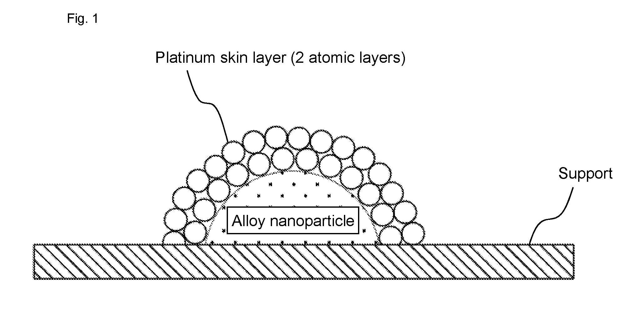
The present disclosure provides the hydrogen evolution catalyst having superior hydrogen generation efficiency. According to the present disclosure, there is provided a hydrogen evolution catalyst comprising a platinum skin layer on a surface of an alloy nanoparticle composed of an alloy of platinum and transition metal.
| Inventors: | Uchida; Hiroyuki; (Yamanashi, JP) ; Nohara; Shinji; (Yamanashi, JP) ; Yano; Hiroshi; (Yamanashi, JP) | ||||||||||
| Applicant: |
|
||||||||||
|---|---|---|---|---|---|---|---|---|---|---|---|
| Assignee: | UNIVERSITY OF YAMANASHI Yamanashi JP |
||||||||||
| Family ID: | 67617637 | ||||||||||
| Appl. No.: | 16/270502 | ||||||||||
| Filed: | February 7, 2019 |
| Current U.S. Class: | 1/1 |
| Current CPC Class: | C25B 11/0494 20130101; C25B 1/10 20130101 |
| International Class: | C25B 11/04 20060101 C25B011/04; C25B 1/10 20060101 C25B001/10 |
Foreign Application Data
| Date | Code | Application Number |
|---|---|---|
| Feb 21, 2018 | JP | 2018-028618 |
Claims
1. A hydrogen evolution catalyst comprising a platinum skin layer on a surface of an alloy nanoparticle composed of an alloy of platinum and transition metal.
2. The hydrogen evolution catalyst of claim 1, wherein the platinum skin layer is 1 to 2 atomic layers.
3. The hydrogen evolution catalyst of claim 1, wherein the transition metal contains at least one selected from the group consisting of iron, cobalt, nickel, manganese, chromium, vanadium, titanium, niobium, molybdenum, lead, and tungsten.
4. The hydrogen evolution catalyst of claim 3, wherein the transition metal is iron or cobalt.
5. The hydrogen evolution catalyst of claim 1, wherein: the transition metal is iron or cobalt; and an atomic composition percentage of the transition metal in the alloy nanoparticle is from 10% to 80%.
6. The hydrogen evolution catalyst of claim 1, wherein the hydrogen evolution catalyst is dispersed on a support to form a supported catalyst.
7. The hydrogen evolution catalyst of claim 6, wherein the support contains at least one selected from the group consisting of carbon black, graphitized carbon black, acetylene black, amorphous carbon, carbon nanotube, carbon nanohorn, tin oxide, and titanium oxide.
8. A hydrogen generation apparatus comprising a DC voltage source and a catalyst cell, wherein: the catalyst cell comprises an anode catalyst layer, an electrolyte, and a cathode catalyst layer in this order; the DC voltage source is configured to apply a DC voltage between the anode catalyst layer and the cathode catalyst layer; and the cathode catalyst layer includes the hydrogen evolution catalyst of claim 1.
9. The hydrogen generation apparatus of claim 8, wherein the electrolyte is a solid polymer electrolyte membrane.
10. A hydrogen generation method for generating hydrogen by using the hydrogen generation apparatus of claim 8, comprising: generating protons by supplying a proton source to the anode catalyst layer while a DC voltage is applied between the anode catalyst layer and the cathode catalyst layer; and reducing the protons in the cathode catalyst layer to generate hydrogen.
Description
TECHNICAL FIELD
[0001] The present disclosure relates to a hydrogen evolution catalyst, a hydrogen generation apparatus, and a hydrogen generation method.
BACKGROUND
[0002] Patent Literature 1 discloses a hydrogen refining pressure-boosting apparatus, and Patent Literature 2 discloses a water electrolysis apparatus. In both of Patent Literatures 1 and 2, disclosed is a configuration which comprises an anode catalyst layer, a solid polymer electrolyte membrane, and a cathode catalyst layer in this order, and in which protons are reduced in the cathode catalyst layer to generate hydrogen.
CITATION LIST
Patent Literature
[0003] Patent Literature 1: WO2015/020065
[0004] Patent Literature 2: JP2016-47524A
[0005] Patent Literature 3: WO2013/035698
SUMMARY
[0006] In a hydrogen generation apparatus such as those of Patent Literatures 1 and 2, a noble metal such as platinum is usually used as a catalyst of the cathode catalyst layer; however, since noble metal is expensive, it is desired to reduce the amount of them.
[0007] The present disclosure has been made in consideration of the afore-mentioned circumstances and provides a hydrogen evolution catalyst excellent in hydrogen generation efficiency.
[0008] According to the present disclosure, there is provided a hydrogen evolution catalyst comprising a platinum skin layer on a surface of an alloy nanoparticle composed of an alloy of platinum and transition metal.
[0009] The inventors found that a catalyst configured by coating an alloy nanoparticle with a platinum skin layer functions as a hydrogen evolution catalyst excellent in hydrogen generation efficiency and completed the present disclosure. Since the hydrogen evolution catalyst of the present disclosure has high mass activity, the amount of noble metal used can be reduced.
[0010] Hereinafter, various embodiments of the present disclosure will be exemplified. The embodiments shown below can be combined with each other.
[0011] Preferably, the platinum skin layer is 1 to 2 atomic layers.
[0012] Preferably, the transition metal contains at least one selected from the group consisting of iron, cobalt, nickel, manganese, chromium, vanadium, titanium, niobium, molybdenum, lead, and tungsten.
[0013] Preferably, the transition metal is iron or cobalt.
[0014] Preferably, the transition metal is iron or cobalt, and an atomic composition percentage of the transition metal in the alloy nanoparticle is from 10% to 80%.
[0015] Preferably, the hydrogen evolution catalyst is a supported catalyst which is dispersed on a support.
[0016] Preferably, the support contains at least one selected from the group consisting of carbon black, graphitized carbon black, acetylene black, amorphous carbon, carbon nanotube, carbon nanohorn, tin oxide, and titanium oxide.
[0017] According to another aspect of the present disclosure, there is provided a hydrogen generation apparatus comprising a DC voltage source and a catalyst cell, wherein: the catalyst cell comprises an anode catalyst layer, an electrolyte, and a cathode catalyst layer in this order; the DC voltage source is configured to apply a DC voltage between the anode catalyst layer and the cathode catalyst layer; and the cathode catalyst layer includes the afore-mentioned hydrogen evolution catalyst.
[0018] Preferably, the electrolyte is a solid polymer electrolyte membrane.
[0019] According to further another aspect of the present disclosure, there is provided a hydrogen generation method using the afore-mentioned hydrogen generation apparatus to generate hydrogen, wherein the method comprises: supplying a proton source to the anode catalyst layer to generate protons while a DC voltage is applied between the anode catalyst layer and the cathode catalyst layer; and reducing the protons in the cathode catalyst layer to generate hydrogen.
DESCRIPTION OF THE DRAWINGS
[0020] The foregoing aspects and many of the attendant advantages of this disclosure will become more readily appreciated as the same become better understood by reference to the following detailed description, when taken in conjunction with the accompanying drawings, wherein:
[0021] FIG. 1 is a conceptual diagram showing the configuration of the hydrogen evolution catalyst according to the present embodiments.
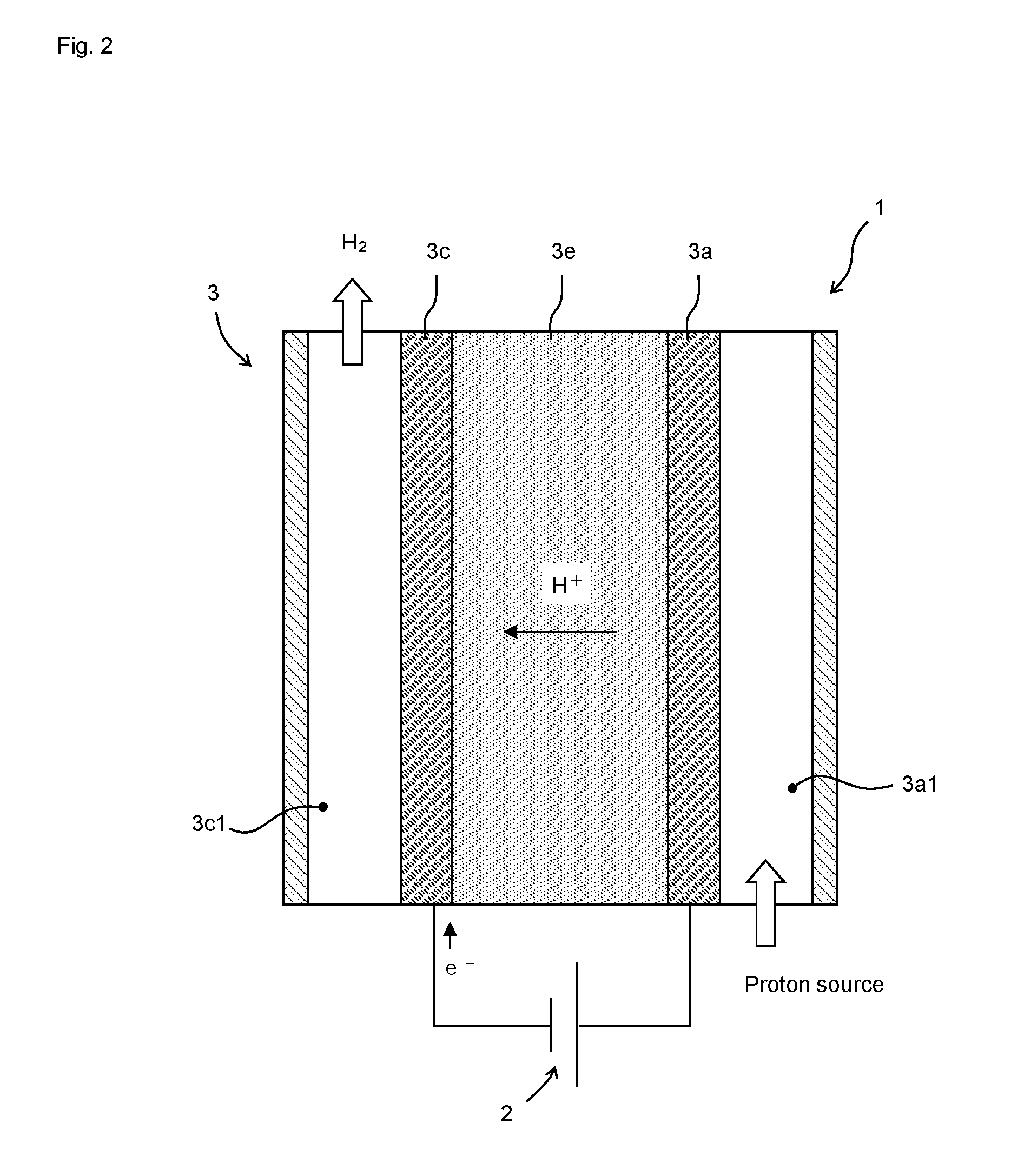
[0022] FIG. 2 is a configuration diagram of a hydrogen generation apparatus 1.
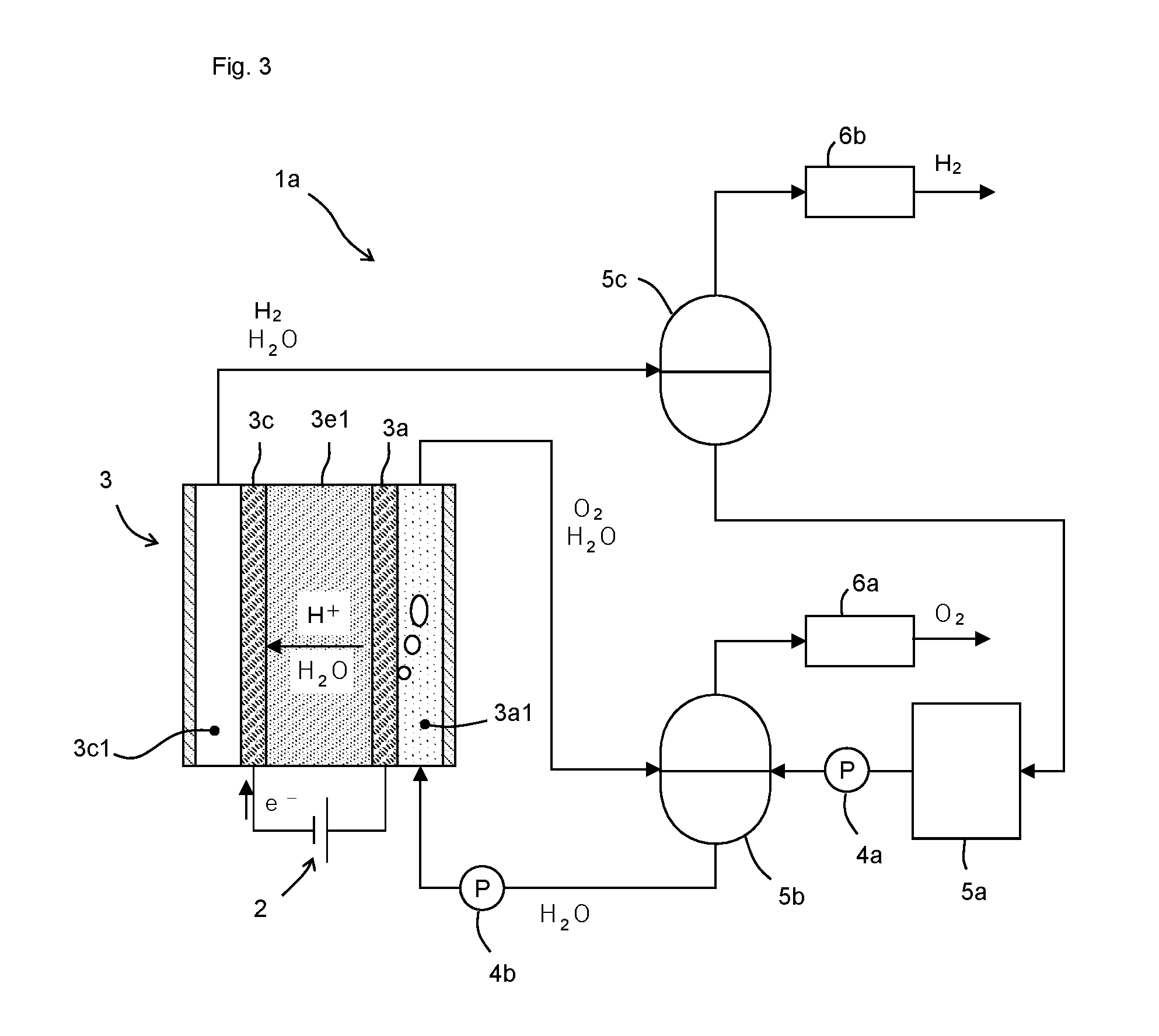
[0023] FIG. 3 is a configuration diagram of a water electrolysis apparatus 1a.
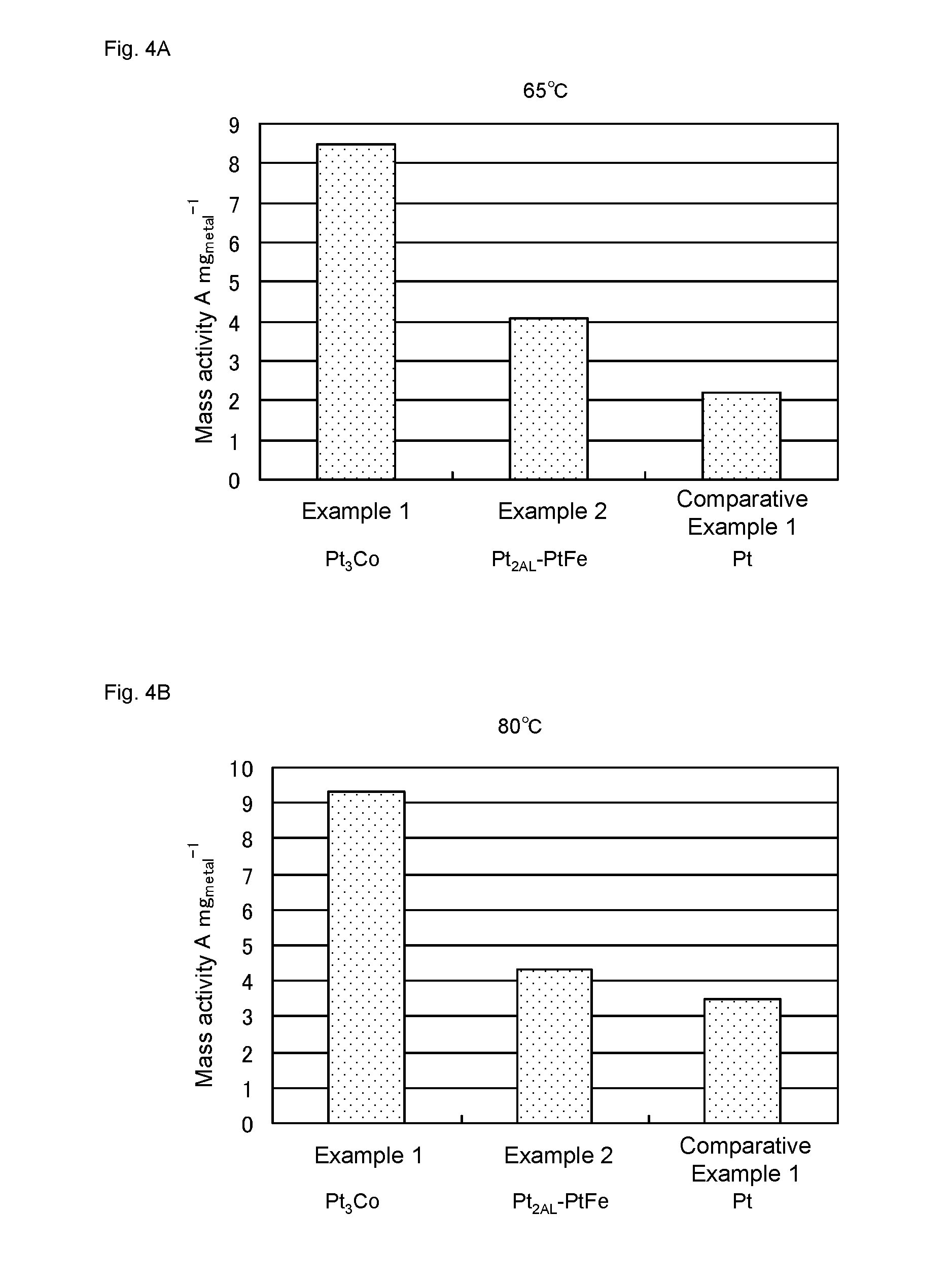
[0024] FIG. 4 shows mass activity of catalysts of Examples 1-2 and Comparative Example 1. FIG. 4A and FIG. 4B shows values obtained by measurement at 65.degree. C. and 80.degree. C., respectively.
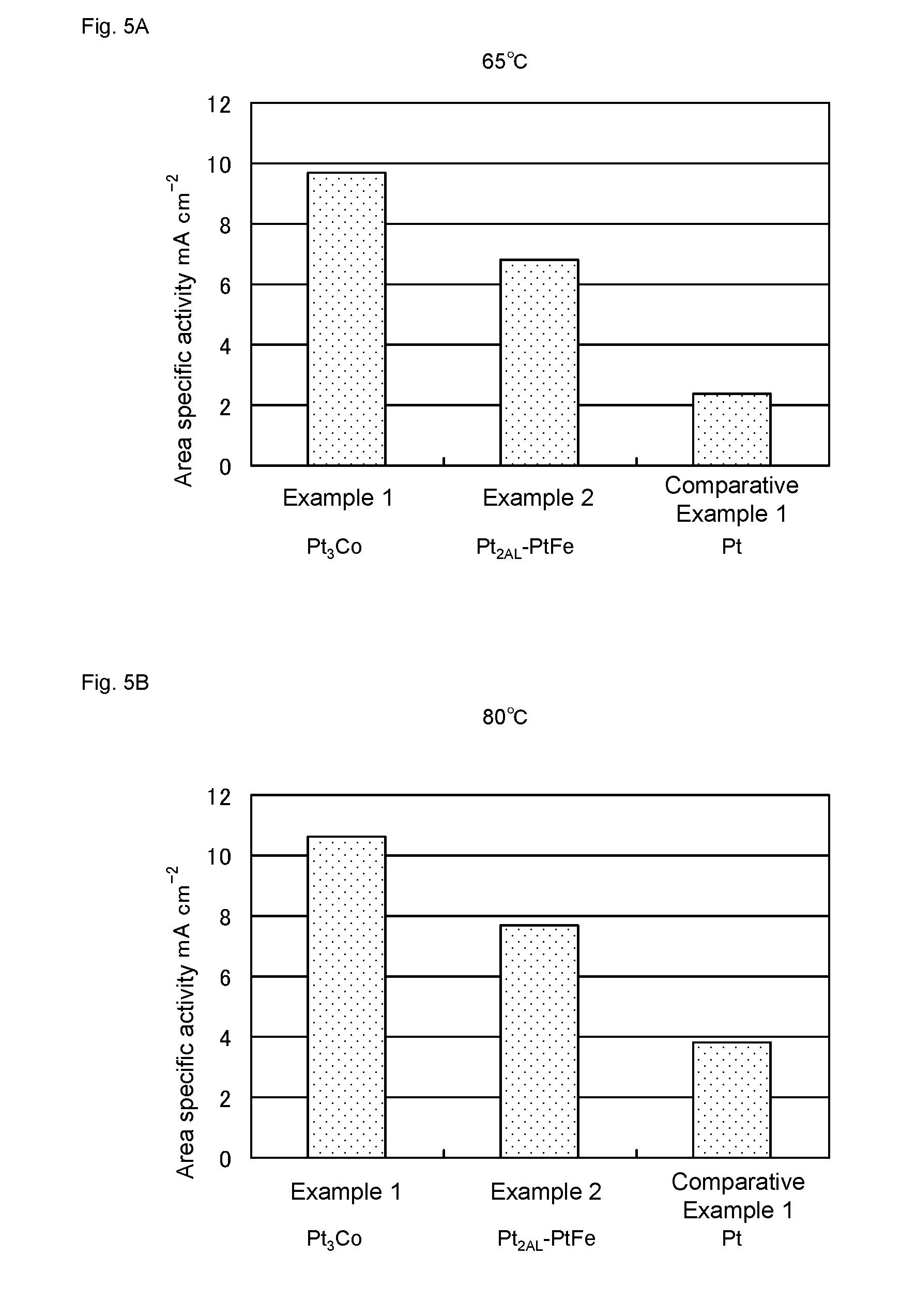
[0025] FIG. 5 shows area specific activity of the catalysts of Examples 1-2 and Comparative Example 1. FIG. 5A and FIG. 5B shows values obtained by measurement at 65.degree. C. and 80.degree. C., respectively.
[0026] FIG. 6 shows I-V characteristic of a water electrolysis cell of Example 2A.
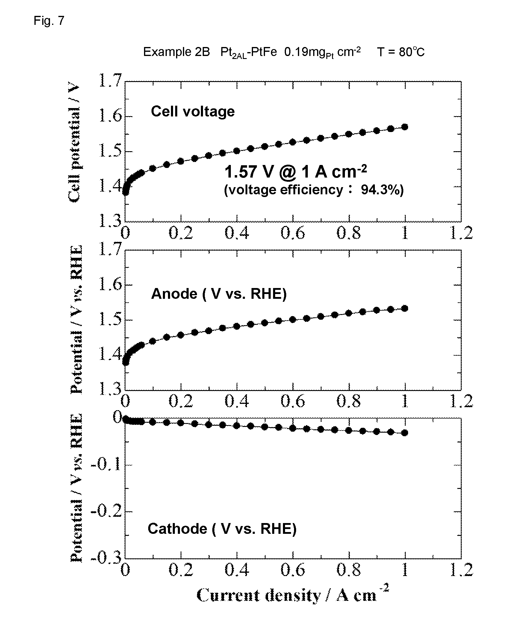
[0027] FIG. 7 shows I-V characteristic of a water electrolysis cell of Example 2B.
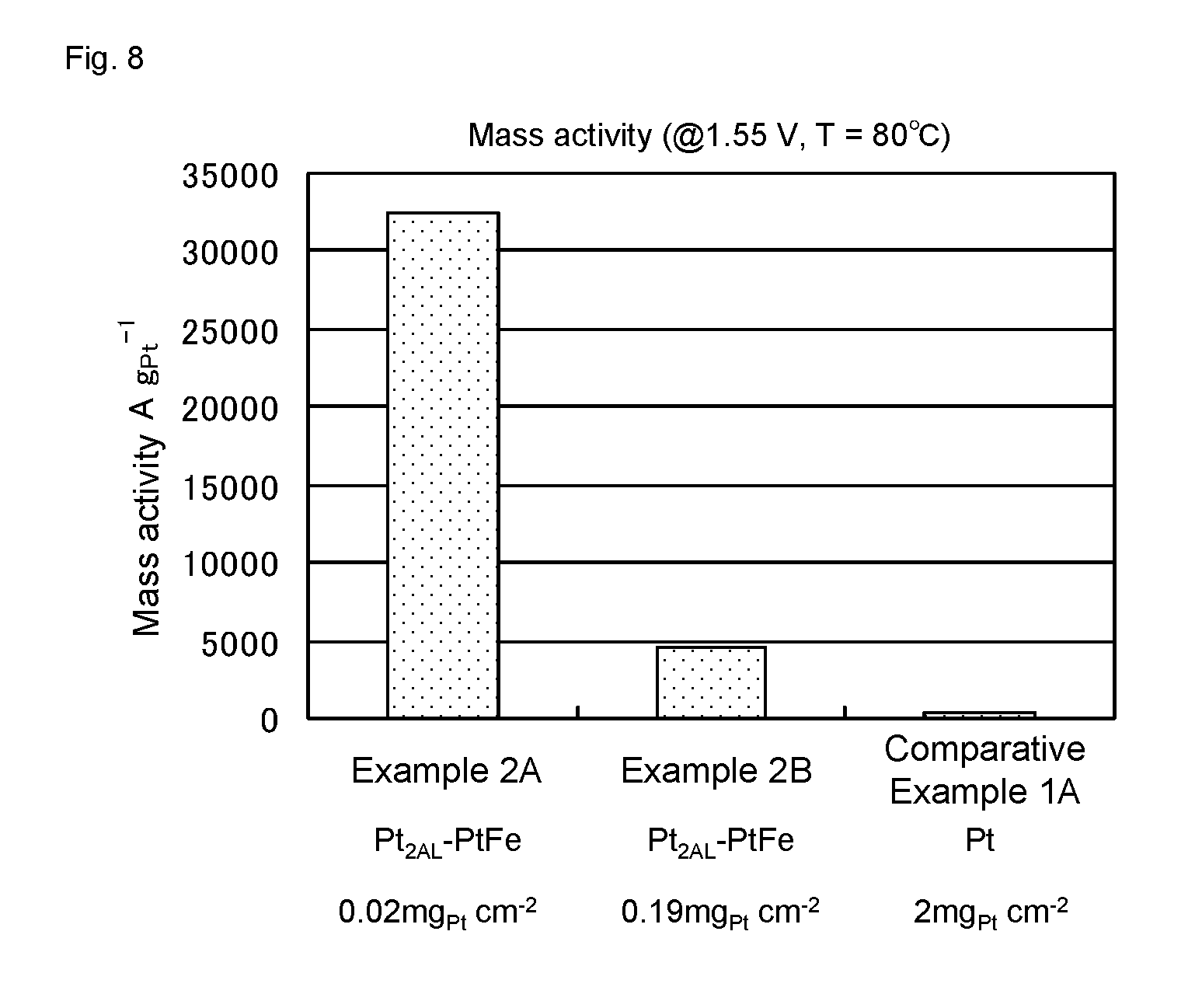
[0028] FIG. 8 shows mass activity of water electrolysis cells of Examples 2A-2B and Comparative Example 1A.
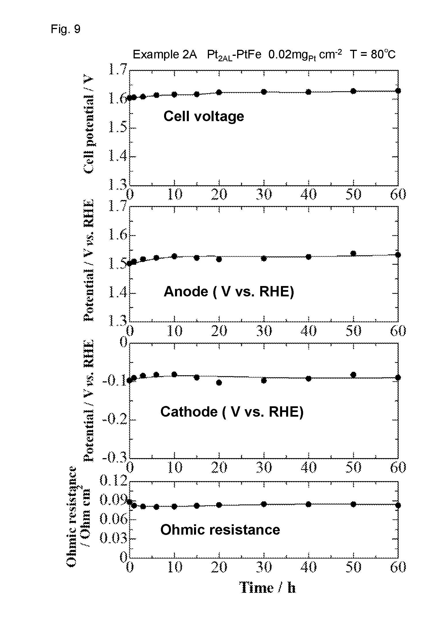
[0029] FIG. 9 shows the result of cell performance stability evaluation of the water electrolysis cell in Example 2A.
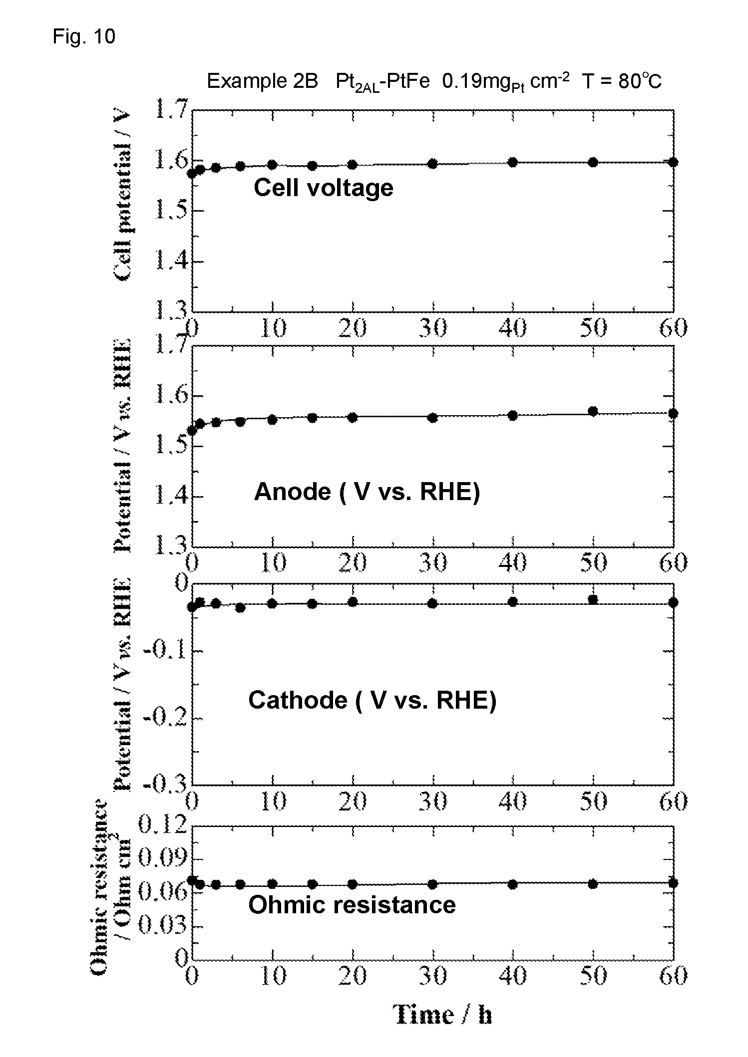
[0030] FIG. 10 shows the result of cell performance stability evaluation of the water electrolysis cell in Example 2B.
[0031] FIG. 11 shows I-V characteristic of the water electrolysis cell of Example 2B, before and after the cell performance stability evaluation.
DETAILED DESCRIPTION
[0032] Hereinafter, the embodiments of the present disclosure will be described with reference to the drawings. Various features described in the embodiments shown below can be combined with each other. Furthermore, the disclosure is independently established for each feature.
[0033] 1. Configuration of Hydrogen Evolution Catalyst
[0034] The hydrogen evolution catalyst functions as a catalyst for a reaction in which protons are reduced to evolve hydrogen. FIG. 1 is a conceptual diagram showing the configuration of the hydrogen evolution catalyst according to the present embodiments. The alloy nanoparticle composed of an alloy of platinum and transition metal is coated with the platinum skin layer composed of platinum atoms. There is no particular limitation regarding the types of the transition metal, so long as it can provide the platinum skin layer composed of platinum atoms on the surface thereof in a state of the alloy nanoparticle with platinum. As the transition metal, an element/elements of the 4th to 6th rows can be used, and in particular, an element/elements of the 4th row are preferable. The transition metal specifically includes at least one selected from, for example, iron, cobalt, nickel, manganese, chromium, vanadium, titanium, niobium, molybdenum, lead, and tungsten. The transition metal is preferably iron, cobalt, nickel, which are elements of the 4th row, and more preferably, iron or cobalt. Mass activity (catalyst activity per unit mass) is improved by containing these metals.
[0035] Herein, the atomic composition percentage of the transition metal in the alloy nanoparticle is preferably from 10% to 80%. Specifically, examples of the atomic composition percentage are, 10, 15, 20, 25, 30, 35, 40, 45, 50, 55, 60, 65, 70, 75, 80%, and the atomic composition percentage can be between any two of the values selected from these. When the atomic composition percentage is in this range, the mass activity is particularly high.
[0036] There is no particular limitation regarding an average particle diameter of the alloy nanoparticles, and the average particle diameter is, for example, 1 to 8 nm. When the average particle diameter is too small, it would not be easy to produce stably the alloy nanoparticles. On the other hand, when the average particle diameter is too large, an average particle diameter of the resulting catalyst nanoparticles would also be large, and thus the mass activity tends to become low. Specifically, examples of the average particle diameter of the alloy nanoparticles are, 1.0, 1.5, 2.0, 2.5, 3.0, 3.5, 4.0, 4.5, 5.0, 5.5, 6.0, 6.5, 7.0, 7.5, 8.0 nm, and the average particle diameter can be between any two of the values selected from these. In the present specification, an "average particle diameter" means herein a value obtained by arithmetically averaging diameters of circumscribed circles of each nanoparticle measured in a TEM image. The number of measurement samples is, for example, 500 or more. Furthermore, it is preferable that the particle diameters of the alloy nanoparticles are as even as possible. It is preferable that 70% or more of the alloy nanoparticles have the particle diameter within .+-.30% of the average particle diameter, and further preferable that they have the particle diameter within .+-.25, .+-.20, or .+-.15% of the average particle diameter.
[0037] There is no particular limitation regarding a thickness of the platinum skin layer, and it is preferably 1 to 2 atomic layers, and more preferably 2 atomic layers. This is because when the platinum skin layer is too thin, the coating of the alloy nanoparticles may be insufficient in some cases. For example, in the case of 1 atomic layer, the underlying alloy may dissolve from incomplete portions of the platinum skin layer under high temperature, and thus there is a possibility of approaching characteristics of a catalyst only supporting pure platinum. On the other hand, when the platinum skin layer is too thick, the electronic effect of the alloy nanoparticles may be shielded by the platinum skin layer in some cases. For example, in the case of 3 atomic layers, the thick platinum skin layer may behave in a same manner as pure platinum, and thus there is a possibility of approaching characteristics of a conventional pure platinum catalyst. Here, in FIG. 1, the case of 2 atomic layers is shown as an example.
[0038] The hydrogen evolution catalyst is preferably dispersed on the support. There is no particular limitation regarding the support, and examples thereof include carbon black, graphitized carbon black, acetylene black, amorphous carbon, carbon nanotube, carbon nanohorn, tin oxide, titanium oxide and the like.
[0039] 2. Production Method of Hydrogen Evolution Catalyst
[0040] The hydrogen evolution catalyst can be produced by forming the platinum skin layer on the surface of the alloy nanoparticle.
[0041] In one example, the alloy nanoparticles can be produced by the nanocapsule method disclosed in Patent Literature 3. In the nanocapsule method, platinum precursors and transition metal precursors are encapsulated in a nanocapsule formed by mixing a solvent having a hydrophilic group and a non-aqueous solvent, and then a nanocapsule solution containing the alloy nanoparticles can be prepared by reducing these precursors. Furthermore, by mixing and agitating the nanocapsule solution containing the alloy nanoparticles and the support, the alloy nanoparticles can be dispersed on the support.
[0042] The platinum skin layer can be formed on the surface of the alloy nanoparticles by performing either or both of thermal treatment and plating on the alloy nanoparticles thus obtained.
[0043] The heat treatment can be performed, for example, in hydrogen. Platinum is thereby precipitated on the surface of the alloy nanoparticles to form the platinum skin layer.
[0044] The plating can be performed, for example, by the hydrogen bubbling method described in Patent Literature 2. In the hydrogen bubbling method, the platinum precursors are reduced on the surface of the alloy nanoparticles to coat the alloy nanoparticles with the platinum atomic layer by performing bubbling of reductant gas including hydrogen gas (hereinafter, also referred to as "hydrogen bubbling") in a condition where the alloy nanoparticles and the aqueous platinum precursors dispersed in a water-containing solvent (for example, water) are co-existing. The plating may be performed by the nanocapsule method described in Patent Literature 3.
[0045] 3. Hydrogen Generation Apparatus, Hydrogen Generation Method
[0046] As shown in FIG. 2, the hydrogen generation apparatus 1 according to one embodiment of the present disclosure comprises a DC voltage source 2 and a catalyst cell 3. The catalyst cell 3 comprises an anode catalyst layer 3a, an electrolyte 3e, and a cathode catalyst layer 3c in this order. A DC voltage source 2 is configured to apply a DC voltage between the anode catalyst layer 3a and the cathode catalyst layer 3c. The DC voltage source 2 applies a voltage so as to move electrons from the anode catalyst layer 3a toward the cathode catalyst layer 3c. An anode flow channel 3a1 is provided adjacent to the anode catalyst layer 3a. A cathode flow channel 3c1 is provided adjacent to the cathode catalyst layer 3c. The electrolyte 3e may be a liquid, but from the viewpoint of ease of handling, a solid polymer electrolyte membrane is preferable. The catalyst layers 3a and 3c can be formed by applying a catalyst ink on an electrode or the solid polymer electrolyte membrane, wherein the catalyst ink is formed by dispersing a catalyst in a dispersion medium.
[0047] A catalyst that promotes a reaction in which protons are generated from a proton source supplied to the anode flow channel 3a1 is supported in the anode catalyst layer 3a. When the hydrogen generation apparatus 1 is a hydrogen refining pressure-boosting apparatus, the proton source is hydrogen. As the anode catalyst, a catalyst promoting a protonation reaction of hydrogen is used, and nanoparticles of Pt alone, PtRu alloy and the like can be used. When the hydrogen generation apparatus 1 is a water electrolysis apparatus, the proton source is water. As the anode catalyst, a catalyst promoting a water electrolysis reaction is used, and a catalyst in which Pt fine particles and IrO.sub.2 fine particles are mixed, a catalyst in which Pt or Ir nanoparticles are dispersed in tin oxide as disclosed in Patent Literature 2, and the like can be used.
[0048] A catalyst that promotes a reaction in which protons reaching the cathode catalyst layer 3c through the electrolyte 3e are reduced to generate hydrogen is supported in the cathode catalyst layer 3c. As such a catalyst, the hydrogen evolution catalyst according to the present embodiment can be used. Since the hydrogen evolution catalyst according to the present embodiment has very high mass activity, the amount of noble metal used can be reduced by using the hydrogen evolution catalyst according to the present embodiment.
[0049] Next, the hydrogen generation method using the hydrogen generation apparatus 1 will be described.
[0050] First, the proton source is supplied to the anode catalyst layer 3a through the anode flow channel 3a1 while a DC voltage is applied between the anode catalyst layer 3a and the cathode catalyst layer 3c. Protons are thereby generated from the proton source and released to the electrolyte 3e.
[0051] In the cathode catalyst layer 3c, the protons reaching the cathode catalyst layer 3c through the electrolyte 3e are reduced to generate hydrogen. The generated hydrogen is extracted out of the catalyst cell 3 through the cathode flow channel 3c1. The extracted hydrogen is stored in a tank and the like, and then used.
[0052] 4. Water Electrolysis Apparatus
[0053] Here, with reference to FIG. 3, the water electrolysis apparatus which is an example of the hydrogen generation apparatus 1 will be described in more detail.
[0054] The water electrolysis apparatus 1a comprises the DC voltage source 2, the catalyst cell 3, pumps 4a and 4b, tanks (a water tank 5a, an oxygen separation tank 5b, a hydrogen separation tank 5c), and dehumidifiers 6a and 6b. Each component is connected to each other by piping. In the catalyst cell 3, a solid polymer electrolyte membrane 3e1 is provided as the electrolyte 3e.
[0055] The pump 4a is disposed between the water tank 5a and the oxygen separation tank 5b, and transports water in the water tank 5a to the oxygen separation tank 5b. The pump 4b is disposed between the oxygen separation tank 5b and the catalyst cell 3, and transports water in the oxygen separation tank 5b into the anode flow channel 3a1.
[0056] The water transported into the anode flow channel 3a1 is partly electrolyzed to generate oxygen in the anode flow channel 3a1 and to generate hydrogen in the cathode flow channel 3c1.
[0057] The generated oxygen and unreacted water are exhausted from the anode flow channel 3a1 and injected into the oxygen separation tank 5b. In the oxygen separation tank 5b, the water and the oxygen are separated. The oxygen is dehumidified by the dehumidifier 6a, after being exhausted from the oxygen separation tank 5b. The dehumidified oxygen is used in another process, stored, or released into the atmosphere. The water in the oxygen separation tank 5b is supplied again to the catalyst cell 3.
[0058] The generated hydrogen and water passing through the solid polymer electrolyte membrane 3e1 are exhausted from the cathode flow channel 3c1 and injected into the hydrogen separation tank 5c. In the hydrogen separation tank 5c, the water and the hydrogen are separated. The hydrogen is dehumidified by the dehumidifier 6b, after being discharged from the hydrogen separation tank 5c. The dehumidified hydrogen is used in another process or stored in a tank or the like. The water in the hydrogen separation tank 5c is transferred to the water tank 5a.
[0059] Since water is consumed by the water electrolysis reaction, the consumed amount of water is replenished from the outside, accordingly.
EXAMPLES
[0060] 1. Production of Catalyst
[0061] The catalysts of Examples 1 and 2 were produced by the method shown below. In Example 1, a catalyst (Pt.sub.3Co), in which Pt.sub.3Co nanoparticles are coated with a platinum skin layer of 1 atomic layer, was produced. In Example 2, a catalyst (Pt.sub.2AL--PtFe), in which PtFe nanoparticles are coated with a platinum skin layer of 2 atomic layers, was produced.
Example 1 (Pt.sub.3Co)
[0062] Pt(acac).sub.2 (0.375 mmol), Co(acac).sub.3 (0.125 mmol), 1,2-hexadecanediol (1 mmol, 260 mg), and diphenyl ether (12.5 ml, 13.5 g, 79.3 mmol) were charged in a beaker, and the mixture was agitated and mixed with a stirrer for 10 minutes at an elevated temperature of 100.degree. C. Subsequently, oleic acid (0.25 mmol, 85 .mu.l) and oleylamine (0.25 mmol, 80 .mu.l) were added, and the temperature was raised to 200.degree. C. with stirring. Then, the mixture was further agitated for 20 minutes to obtain a nanocapsule solution. To the nanocapsule solution thus obtained, LiB(C.sub.2H.sub.5).sub.3H.THF solution (1M (mol/L), 1.0 ml, 1 mmol) was gradually dropped over 2 minutes, and the mixture was agitated for 5 minutes. Then, the temperature of the mixture was raised to 260.degree. C., and reduction reaction was carried out at this temperature under reflux for 20 minutes to obtain a solution A containing Pt.sub.3Co particles in the nanocapsule. Then, the solution A was cooled to approximately 100.degree. C., a support was added and agitated so that the amount of Pt.sub.3Co supported would be 26.9 wt % with respect to the amount of the support (graphitized acetylene black, 250 m.sup.2/g), and the Pt.sub.3Co nanoparticles were dispersed on the support in a state where organic protective groups remained. After filtering the mixture, the filtrate was subjected to vacuum drying at 60.degree. C. Heat treatment was then carried out under hydrogen gas for removing the remaining organic solvent and depositing Pt on the surface of the Pt.sub.3Co nanoparticles simultaneously, to obtain the catalyst of Example 1.
[0063] Line analysis by scanning transmission electron microscope with energy dispersive X-ray spectroscopy (STEM-EDS) was conducted with this catalyst, and it was revealed that Pt and Co co-existed at the center, while only Pt existed in the region of approximately 0.25 nm from both edges. These results show that the Pt skin layer was formed with a thickness of approximately 0.25 nm (a thickness of 1 atomic layer). Furthermore, the Pt:Co ratio of this catalyst was 3.2:1.
[0064] Furthermore, TEM observation shows that an average particle diameter of the catalyst particles was 2.9.+-.0.5 nm (the value after .+-.indicates a standard deviation value (nm)).
Example 2 (Pt.sub.2AL--PtFe)
[0065] (1) Preparation of PtFe Nanoparticles
[0066] Pt(acac).sub.2 (0.125 mmol), Fe(acac).sub.3 (0.125 mmol), 1,2-hexadecanediol (1 mmol, 260 mg)), and diphenyl ether (12.5 ml, 13.5 g, 79.3 mmol) were charged in a beaker, and the mixture was agitated and mixed with a stirrer for 10 minutes at an elevated temperature of 100.degree. C. Subsequently, oleic acid (0.25 mmol, 85 .mu.l) and oleylamine (0.25 mmol, 80 .mu.l) were added, and the temperature was raised to 200.degree. C. with stirring. Then, the mixture was further agitated for 20 minutes to obtain a nanocapsule solution. To the nanocapsule solution thus obtained, LiB(C.sub.2H.sub.5).sub.3H.THF solution (1M (mol/L), 1.0 ml, 1 mmol) was gradually dropped over 2 minutes, and the mixture was agitated for 5 minutes. Then, the temperature of the mixture was raised to 260.degree. C., and reduction reaction was carried out at this temperature under reflux for 20 minutes to obtain a solution A containing PtFe particles in the nanocapsule. Then, the solution A was cooled to approximately 100.degree. C., a support was added and agitated so that the amount of PtFe supported would be 31.5 wt % with respect to the amount of the support (graphitized acetylene black, 800 m.sup.2/g), and the PtFe nanoparticles were dispersed on the support in a state where organic protective groups remained. After filtering the mixture, the filtrate was subjected to vacuum drying at 60.degree. C. Heat treatment was then carried out under hydrogen gas for removing the remaining organic solvent and depositing Pt on the surface of the PtFe nanoparticles simultaneously.
[0067] (2) Hydrogen Bubbling
[0068] As Pt skin precursors, tetraammine platinum hydroxide solution ([Pt(NH.sub.3).sub.4](OH).sub.2) in an amount for 1 atomic layer of Pt was dissolved in purified water (10 mL) to prepare a Pt skin precursor solution. The PtFe nanoparticles obtained in (1) were mixed in this solution, and the solution was boiled for 10 minutes. Subsequently, after waiting for the reaction solution to reach 60.degree. C., hydrogen bubbling was performed at 60.degree. C. for 1 hour, using 5% hydrogen gas. As a result, the Pt skin layer was formed uniformly on the surface of each of the PtFe nanoparticles, to obtain the catalyst of Example 2.
[0069] Line analysis by scanning transmission electron microscope energy dispersive X-ray spectroscopy (STEM-EDS) was conducted with this catalyst, and it was revealed that Pt and Co co-existed at the center, while only Pt existed in the region of approximately 0.5 nm from both ends. These results show that the Pt skin layer was formed with a thickness of approximately 0.5 nm (a thickness of 2 atomic layers). Furthermore, the Pt:Fe ratio of this catalyst was 2.7:1.
[0070] Furthermore, TEM observation shows that an average particle diameter of the catalyst particles was 2.9.+-.0.4 nm.
[0071] 2. Activity Evaluation Using Channel Flow Cell
[0072] Activity evaluation was performed with the catalysts of Examples 1-2 and Comparative Example 1 by using a channel flow cell. As the catalyst of Comparative Example 1, a platinum catalyst which is commercially available (TEC10E50E, Tanaka Kikinzoku Kogyo) was used.
[0073] The channel flow cell comprises a working electrode of Au, a counter electrode of Pt, and a reference electrode of a reversible hydrogen electrode (RHE). The catalyst to be evaluated was fixed on the working electrode so that metal mass of the catalyst would be 0.011 mg.sub.metal/cm.sup.2. In order to fix the catalyst, the catalyst in a state being dispersed in ethanol was dropped on the working electrode and dried, and then a Nafion solution was dropped and dried so that a dry film thickness would be 0.1 .mu.m.
[0074] While 0.1 M HClO.sub.4 was flowing at an average flow rate of 111 cms.sup.-1 in the channel flow cell, a voltage was applied between the working electrode and the counter electrode so that the potential of the working electrode would be -30 mV relative to the RHE, to evolve hydrogen at the working electrode. A current value was measured, and then mass activity MA (current value per catalyst metal mass) and area specific activity (current value per active surface area) were calculated. The measurement was carried out at 65.degree. C. and 80.degree. C. The active surface area was calculated from the peak area of hydrogen adsorption wave specific to an electrochemical reaction on the Pt surface, by acquiring cyclic voltammogram (CV) in a N.sub.2 saturated solution.
[0075] The obtained results were shown in FIGS. 4 and 5. As is apparent from FIGS. 4 and 5, the catalysts of Examples 1 and 2 have much higher mass activity and area specific activity than that of Comparative Example 1.
[0076] 3. Production of Water Electrolysis Cell (Catalyst Cell)
[0077] Using the catalysts of Example 2 and Comparative Example 1, the water electrolysis cells of Examples 2A and 2B and Comparative Example 1A were prepared by the following method.
[0078] <Formation of Cathode Catalyst Layer>
[0079] The catalyst (0.5 g; the catalyst of Example 2 in Examples 2A and 2B, and the catalyst of Comparative Example 1 in Comparative Example 1A), water (4.13 g), and ethanol (8.09 g) were added in this order to a zirconia pot containing zirconium beads (.phi. 5 mm and .phi. 15 mm), and then the mixture was agitated with a planetary ball mill at 270 rpm for 30 minutes.
[0080] Subsequently, a Nafion solution (5 wt %, 2.50 g; DE521, E.I. Du Pont de Nemours & Co., Inc.) was added in a zirconia pot, and then the mixture was agitated with the planetary ball mill at 270 rpm for 30 minutes to obtain a catalyst paste. After overnight stabilization treatment using a pot mill, the catalyst paste was applied to one surface of a solid polymer electrolyte membrane (NRE 212) having a thickness of 50 .mu.m by the pulse-swirl-spray (PSS) method, to form a cathode catalyst layer. The amount of catalyst applied was set so that the mass of platinum would be 0.02 mg.sub.Pt/cm.sup.2 and 0.19 mg.sub.Pt/cm.sup.2 in Examples 2A and 2B, respectively, and that the mass of platinum would be 2.0 mg.sub.Pt/cm.sup.2 in Comparative Example 1.
[0081] <Formation of Anode Catalyst Layer>
[0082] Platinum black (0.3 g, specific surface area 10 m.sup.2/g, ISHIFUKU Metal Industry Co., Ltd.), IrO.sub.2 (0.3 g), water (7.95 g), and ethanol (10.88 g) were added in this order to a zirconia pot containing zirconium beads (.phi. 5 mm and .phi. 15 mm), and then the mixture was agitated with a planetary ball mill at 270 rpm for 30 minutes.
[0083] Subsequently, a Nafion solution (5 wt %, 3.95 g) was added in a zirconia pot, and then the mixture was agitated with the planetary ball mill at 270 rpm for 30 minutes to obtain a catalyst paste. Then, the catalyst paste was applied to the other surface of the afore-mentioned solid polymer electrolyte membrane by the pulse-swirl-spray (PSS) method, to form an anode catalyst layer. The amount of catalyst applied was set so that the total mass of platinum and iridium would be 1.0 mg.sub.Pt+Ir/cm.sup.2 in Examples 2A and 2B, and that the total mass of platinum and iridium would be 2.0 mg.sub.Pt+Ir/cm.sup.2 in Comparative Example 1.
[0084] <Hot Pressing Step>
[0085] According to the steps described above, the catalyst-coated membrane in which the solid polymer electrolyte membrane was sandwiched between the cathode catalyst layer and the anode catalyst layer was obtained. This catalyst-coated membrane was dried at 60.degree. C. for 12 hours, and then hot pressed at 140.degree. C. and 10 kgfcm.sup.-2 for 3 minutes.
[0086] <Fabrication of Water Electrolysis Cell>
[0087] The afore-mentioned catalyst-coated membrane was incorporated in a JARI standard cell to fabricate a water electrolysis cell. A carbon paper with a thickness of 230 .mu.m was disposed in the cathode, as a gas diffusion layer. A platinum-coated titanium fiber mesh with a thickness of 320 .mu.m was disposed in the anode, as a gas diffusion layer.
[0088] 4. I-V Characteristic Evaluation of Water Electrolysis Cell
[0089] I-V characteristic evaluation was carried out with the water electrolysis cells of Examples 2A and 2B and Comparative Example 1A by the following method.
[0090] While water at 80.degree. C. was supplied at 20 ml/min in the anode flow channel, a voltage (cell voltage) was applied between the cathode catalyst layer and the anode catalyst layer to electrolyze water. A current was measured to obtain a current density (per unit area) of the cathode catalyst layer. The applied voltage was increased until a current density of the cathode catalyst layer reached 1 Acm.sup.-2.
[0091] The measurement results of the I-V characteristic for Examples 2A and 2B are shown in FIGS. 6 and 7. In Examples 2A-2B, the results show that a current density of 1 Acm.sup.-2 was achieved with a relatively low applied voltage of 1.57 to 1.60 V. The voltage efficiency at that electrolysis voltage was as high as 92.3 to 94.3%.
[0092] 5. Comparison of Mass Activities
[0093] A current density when the cell voltage was set at 1.55 V was measured for the water electrolysis cells of Examples 2A and 2B and Comparative Example 1A, to calculate mass activity per 1 gram of Pt. The results are shown in FIG. 8. As shown in FIG. 8, in Examples 2A and 2B, the mass activity was much higher than that in Comparative Example 1A.
[0094] 6. Cell Performance Stability Cell performance stability evaluation by water electrolysis for 60 hours was carried out under the same conditions as in "4. I-V Characteristic Evaluation of Water Electrolysis Cell", except that the cell voltage was set so as to maintain a current density of 1 Acm.sup.-2. The results are shown in FIGS. 9 and 10. As shown in FIGS. 9 and 10, performance change within 60 hours was very small in both of Examples 2A and 2B.
[0095] For the water electrolysis cell of Example 2B, I-V characteristic before and after cell performance stability evaluation was evaluated. The results are shown in FIG. 11. As shown in FIG. 11, a change in the cell voltage was mostly caused by a potential change of the anode including a commercially available catalyst, and a potential change of the cathode including Pt.sub.2AL--PtFe/C was very small.
[0096] In this regard, while each of FIGS. 9 to 11 shows the results of the cell performance stability evaluation by water electrolysis for 60 hours, similar results were obtained by cell performance stability test after 1000 hours. That is, even in the operation for 1000 hours, the water electrolysis cells have sufficient stability, maintaining the initial characteristics thereof.
[0097] While illustrative embodiments have been illustrated and described, it will be appreciated that various changes can be made therein without departing from the spirit and scope of the invention.
* * * * *
D00000
D00001
D00002
D00003
D00004
D00005
D00006
D00007
D00008
D00009
D00010
D00011
XML
uspto.report is an independent third-party trademark research tool that is not affiliated, endorsed, or sponsored by the United States Patent and Trademark Office (USPTO) or any other governmental organization. The information provided by uspto.report is based on publicly available data at the time of writing and is intended for informational purposes only.
While we strive to provide accurate and up-to-date information, we do not guarantee the accuracy, completeness, reliability, or suitability of the information displayed on this site. The use of this site is at your own risk. Any reliance you place on such information is therefore strictly at your own risk.
All official trademark data, including owner information, should be verified by visiting the official USPTO website at www.uspto.gov. This site is not intended to replace professional legal advice and should not be used as a substitute for consulting with a legal professional who is knowledgeable about trademark law.