Alkali-free Borosilicate Glasses With Low Post-hf Etch Roughness
Gross; Timothy Michael ; et al.
U.S. patent application number 16/272305 was filed with the patent office on 2019-08-22 for alkali-free borosilicate glasses with low post-hf etch roughness. The applicant listed for this patent is Corning Incorporated. Invention is credited to Timothy Michael Gross, Yuhui Jin, Ruchirej Yongsunthon, Liying Zhang.
| Application Number | 20190256404 16/272305 |
| Document ID | / |
| Family ID | 65686130 |
| Filed Date | 2019-08-22 |


| United States Patent Application | 20190256404 |
| Kind Code | A1 |
| Gross; Timothy Michael ; et al. | August 22, 2019 |
ALKALI-FREE BOROSILICATE GLASSES WITH LOW POST-HF ETCH ROUGHNESS
Abstract
An article comprises a glass substrate. The glass substrate has a first surface having a plurality of vias therein, and a second surface parallel to the first surface. At least one of the first surface and the second surface is an etched surface having a surface roughness (Ra) of 0.75 nm or less. The glass substrate comprises, in mol percent on an oxide basis: 65 mol %.ltoreq.SiO.sub.2.ltoreq.75 mol %; 7 mol %.ltoreq.Al.sub.2O.sub.3.ltoreq.15 mol %; 26.25 mol %.ltoreq.RO+Al.sub.2O.sub.3-B.sub.2O.sub.3; 0 mol %.ltoreq.R.sub.2O.ltoreq.2 mol %. RO=MgO+CaO+SrO+BaO+ZnO. R.sub.2O=Li.sub.2O+Na.sub.2O+K.sub.2O+Rb.sub.2O+Cs.sub.2O.
| Inventors: | Gross; Timothy Michael; (Corning, NY) ; Jin; Yuhui; (Painted Post, NY) ; Yongsunthon; Ruchirej; (Painted Post, NY) ; Zhang; Liying; (Painted Post, NY) | ||||||||||
| Applicant: |
|
||||||||||
|---|---|---|---|---|---|---|---|---|---|---|---|
| Family ID: | 65686130 | ||||||||||
| Appl. No.: | 16/272305 | ||||||||||
| Filed: | February 11, 2019 |
Related U.S. Patent Documents
| Application Number | Filing Date | Patent Number | ||
|---|---|---|---|---|
| 62633835 | Feb 22, 2018 | |||
| Current U.S. Class: | 1/1 |
| Current CPC Class: | C03C 3/097 20130101; C03C 3/087 20130101; C03C 23/0025 20130101; C03C 15/00 20130101; C03C 2204/08 20130101; C03C 15/02 20130101; C03C 3/093 20130101 |
| International Class: | C03C 3/093 20060101 C03C003/093; C03C 3/087 20060101 C03C003/087; C03C 15/00 20060101 C03C015/00 |
Claims
1. An article, comprising: a glass substrate comprising: a first surface having a plurality of vias therein; and a second surface parallel to the first surface; wherein at least one of the first surface and the second surface is an etched surface having a surface roughness (Ra) of 0.75 nm or less; wherein the glass substrate comprises, in mol percent on an oxide basis: 65 mol %.ltoreq.SiO.sub.2.ltoreq.75 mol %; 7 mol %.ltoreq.Al.sub.2O.sub.3.ltoreq.15 mol %; 0.1 mol %.ltoreq.B.sub.2O.sub.3.ltoreq.2 mol %; wherein: RO=MgO+CaO+SrO+BaO+ZnO; R.sub.2O=Li.sub.2O+Na.sub.2O+K.sub.2O+Rb.sub.2O+Cs.sub.2O 26.25 mol %.ltoreq.RO+Al.sub.2O.sub.3-B.sub.2O.sub.3; 0 mol %.ltoreq.R.sub.2O.ltoreq.2 mol %; and SiO.sub.2, Al.sub.2O.sub.3, B.sub.2O.sub.3, MgO, ZnO, CaO, SrO, BaO, R.sub.2O, and RO represent the mol percents of the representative oxide components.
2. The article of claim 1, wherein the glass substrate comprises, in mol percent on an oxide basis: 65 mol %.ltoreq.SiO.sub.2.ltoreq.75 mol %; 7 mol %.ltoreq.Al.sub.2O.sub.3.ltoreq.15 mol %; 0.1 mol %.ltoreq.B.sub.2O.sub.3.ltoreq.2 mol %; 0 mol %.ltoreq.P.sub.2O.sub.5.ltoreq.2 mol %; 0 mol %.ltoreq.MgO.ltoreq.6 mol %; 0 mol %.ltoreq.ZnO.ltoreq.4 mol %; 0 mol %.ltoreq.CaO.ltoreq.6 mol %; 0 mol %.ltoreq.SrO.ltoreq.10 mol %; 0 mol %.ltoreq.BaO.ltoreq.10 mol %; 0 mol %.ltoreq.SnO.sub.2.ltoreq.0.5 mol %; 0 mol %.ltoreq.As.sub.2O.sub.3.ltoreq.0.5 mol %; 0 mol %.ltoreq.Sb.sub.2O.sub.3.ltoreq.0.5 mol %; wherein: P.sub.2O.sub.5, Na.sub.2O, K.sub.2O, SnO.sub.2, As.sub.2O.sub.3, Sb.sub.2O.sub.3, represent the mol percents of the representative oxide components.
3. The article of claim 1, wherein the article is the glass substrate.
4. The article of claim 1, wherein the plurality of vias are through vias extending from the first surface to the second surface.
5. The article of claim 1, wherein the plurality of vias are blind vias extending from the first surface toward the second surface without reaching the second surface.
6. The article of claim 1, the article further comprising a carrier; wherein at least one of the first surface and the second surface is etched, has a surface roughness (Ra) of 0.75 nm or less and is bonded to the carrier.
7. The article of claim 6, wherein the carrier has a surface roughness (Ra) of 0.2 nm to 0.4 nm.
8. The article of claim 1, wherein the glass substrate has a thickness of 150 .mu.m or less.
9. The article of claim 1, wherein the glass substrate has a thickness of 90 .mu.m to 110 .mu.m.
10. The article of claim 1, wherein 69 mol %.ltoreq.SiO.sub.2.ltoreq.72 mol %.
11. The article of claim 1, wherein 26.5 mol %.ltoreq.RO+Al.sub.2O.sub.3-B.sub.2O.sub.3.
12. The article of claim 11, wherein 26.75 mol %.ltoreq.RO+Al.sub.2O.sub.3-B.sub.2O.sub.3.
13. The article of claim 11, wherein 27.0 mol %.ltoreq.RO+Al.sub.2O.sub.3-B.sub.2O.sub.3.
14. The article of claim 1, wherein 0 mol %.ltoreq.R.sub.2O.ltoreq.1 mol %.
15. The article of claim 1, wherein 0 mol %.ltoreq.R.sub.2O.ltoreq.0.5 mol %.
16. A method, comprising: forming a plurality of vias in a glass substrate having a first surface and a second surface, including etching at least one of the first surface and the second surface to form an etched surface; wherein the glass substrate comprises, in mol percent on an oxide basis: 65 mol %.ltoreq.SiO.sub.2.ltoreq.75 mol %; 7 mol %.ltoreq.Al.sub.2O.sub.3.ltoreq.15 mol %; 0.1 mol %.ltoreq.B.sub.2O.sub.3.ltoreq.2 mol %; wherein: RO=MgO+CaO+SrO+BaO+ZnO; R.sub.2O=Li.sub.2O+Na.sub.2O+K.sub.2O+Rb.sub.2O+Cs.sub.2O 26.25 mol %.ltoreq.RO+Al.sub.2O.sub.3-B.sub.2O.sub.3; 0 mol %.ltoreq.R.sub.2O.ltoreq.2 mol %; and SiO.sub.2, Al.sub.2O.sub.3, B.sub.2O.sub.3, MgO, ZnO, CaO, SrO, BaO, R.sub.2O, and RO represent the mol percents of the representative oxide components.
17. The method of claim 16, wherein the glass substrate comprises, in mol percent on an oxide basis: 65 mol %.ltoreq.SiO.sub.2.ltoreq.75 mol %; 7 mol %.ltoreq.Al.sub.2O.sub.3.ltoreq.15 mol %; 0.1 mol %.ltoreq.B.sub.2O.sub.3.ltoreq.2 mol %; 0 mol %.ltoreq.P.sub.2O.sub.5.ltoreq.2 mol %; 0 mol %.ltoreq.MgO.ltoreq.6 mol %; 0 mol %.ltoreq.ZnO.ltoreq.4 mol %; 0 mol %.ltoreq.CaO.ltoreq.6 mol %; 0 mol %.ltoreq.SrO.ltoreq.10 mol %; 0 mol %.ltoreq.BaO.ltoreq.10 mol %; 0 mol %.ltoreq.SnO.sub.2.ltoreq.0.5 mol %; 0 mol %.ltoreq.As.sub.2O.sub.3.ltoreq.0.5 mol %; 0 mol %.ltoreq.Sb.sub.2O.sub.3.ltoreq.0.5 mol %; wherein: P.sub.2O.sub.5, Na.sub.2O, K.sub.2O, SnO.sub.2, As.sub.2O.sub.3, Sb.sub.2O.sub.3, represent the mol percents of the representative oxide components.
18. The method of claim 16, wherein the etched surface has a surface roughness (Ra) of 0.75 nm or less.
19. The method of claim 16, wherein 26.5 mol %.ltoreq.RO+Al.sub.2O.sub.3-B.sub.2O.sub.3.
20. The method of claim 19, wherein 26.75 mol %.ltoreq.RO+Al.sub.2O.sub.3-B.sub.2O.sub.3.
Description
[0001] This application claims the benefit of priority to U.S. Provisional Application Ser. No. 62/633,835 filed on Feb. 22, 2018, the content of which is relied upon and incorporated herein by reference in its entirety.
BACKGROUND
Field
[0002] The present disclosure generally relates to articles and methods of forming vias in substrates. In particular, the present disclosure is directed to articles and methods of forming through vias in substrates that include etching processes that preserve the surface roughness (Ra) of a substrate.
Technical Background
[0003] Glass substrates with vias are desirable for many applications, including for use as an interposer used as an electrical interface. Glass interposers have become an attractive alternative to silicon and fiber reinforced polymers. But, some of the processes used in producing glass substrates with vias lead to undesirable surface roughness.
[0004] Accordingly, a need exists for methods for forming vias in substrates while preserving low surface roughnesses (Ra).
SUMMARY
[0005] In a first embodiment, an article comprises a glass substrate. The glass substrate has a first surface having a plurality of vias therein, and a second surface parallel to the first surface. At least one of the first surface and the second surface is an etched surface having a surface roughness (Ra) of 0.75 nm or less. The glass substrate comprises, in mol percent on an oxide basis: [0006] 65 mol %.ltoreq.SiO.sub.2.ltoreq.75 mol %; [0007] 7 mol %.ltoreq.Al.sub.2O.sub.3.ltoreq.15 mol %; [0008] 0.1 mol %.ltoreq.B.sub.2O.sub.3.ltoreq.2 mol %; [0009] wherein: [0010] RO=MgO+CaO+SrO+BaO+ZnO; [0011] R.sub.2O=Li.sub.2O+Na.sub.2O+K.sub.2O+Rb.sub.2O+Cs.sub.2O [0012] 26.25 mol %.ltoreq.RO+Al.sub.2O.sub.3-B.sub.2O.sub.3; [0013] 0 mol %.ltoreq.R.sub.2O.ltoreq.2 mol %; and [0014] SiO.sub.2, Al.sub.2O.sub.3, B.sub.2O.sub.3, MgO, ZnO, CaO, SrO, BaO, R.sub.2O, and RO represent the mol percents of the representative oxide components.
[0015] In a second embodiment, the glass substrate comprises, in mol percent on an oxide basis: [0016] 65 mol %.ltoreq.SiO.sub.2.ltoreq.75 mol %; [0017] 7 mol %.ltoreq.Al.sub.2O.sub.3.ltoreq.15 mol %; [0018] 0.1 mol %.ltoreq.B.sub.2O.sub.3.ltoreq.2 mol %; [0019] 0 mol %.ltoreq.P.sub.2O.sub.5.ltoreq.2 mol %; [0020] 0 mol %.ltoreq.MgO.ltoreq.6 mol %; [0021] 0 mol %.ltoreq.ZnO.ltoreq.4 mol %; [0022] 0 mol %.ltoreq.CaO.ltoreq.6 mol %; [0023] 0 mol %.ltoreq.Sr.sub.0.ltoreq.10 mol %; [0024] 0 mol %.ltoreq.BaO.ltoreq.10 mol %; [0025] 0 mol %.ltoreq.SnO.sub.2.ltoreq.0.5 mol %; [0026] 0 mol %.ltoreq.As.sub.2O.sub.3.ltoreq.0.5 mol %; [0027] 0 mol %.ltoreq.Sb.sub.2O.sub.3.ltoreq.0.5 mol %; [0028] wherein: [0029] P.sub.2O.sub.5, Na.sub.2O, K.sub.2O, SnO.sub.2, As.sub.2O.sub.3, Sb.sub.2O.sub.3, represent the mol percents of the representative oxide components.
[0030] In a third embodiment, for the article of any of the first through second embodiments, the article of the first embodiment is the glass substrate.
[0031] In a fourth embodiment, for the article of any of the first through third embodiments, the plurality of vias are through vias extending from the first surface to the second surface.
[0032] In a fifth embodiments, for the article of any of the first through third embodiments, the plurality of vias are blind vias extending from the first surface toward the second surface without reaching the second surface.
[0033] In a sixth embodiment, for the article of any of the first through fifth embodiments, the article further comprises a carrier. At least one of the first surface and the second surface is etched, has a surface roughness (Ra) of 0.75 nm or less and is bonded to the carrier.
[0034] In a seventh embodiment, for the article of the sixth embodiment, the carrier has a surface roughness (Ra) of 0.2 nm to 0.4 nm.
[0035] In an eighth embodiment, for the article of any of the first through seventh embodiments, the glass substrate has a post-etch thickness of 150 .mu.m or less.
[0036] In a ninth embodiment, for the article of any of the first through eighth embodiments, the glass substrate has a thickness of 90 .mu.m to 110 .mu.m.
[0037] In a tenth embodiment, for the article of any of the first through ninth embodiments, 69 mol %.ltoreq.SiO.sub.2.ltoreq.72 mol %.
[0038] In eleventh through thirteenth embodiments, for the article of any of the first through tenth embodiments, 26.5 mol %.ltoreq.RO+Al.sub.2O.sub.3-B.sub.2O.sub.3, or 26.75 mol %.ltoreq.RO+Al.sub.2O.sub.3-B.sub.2O.sub.3, or 27.0 mol %.ltoreq.RO+Al.sub.2O.sub.3-B.sub.2O.sub.3.
[0039] In a fourteenth and fifteenth embodiments, for the article of any of the first through thirteenth embodiments, 0 mol %.ltoreq.R.sub.2O.ltoreq.1 mol %, or 0 mol %.ltoreq.R.sub.2O.ltoreq.0.5 mol %.
[0040] In a sixteenth embodiment, a method comprises forming a plurality of vias in a glass substrate having a first surface and a second surface. The method includes etching at least one of the first surface and the second surface to form an etched surface. The glass substrate comprises, in mol percent on an oxide basis: [0041] 65 mol %.ltoreq.SiO.sub.2.ltoreq.75 mol % [0042] 7 mol %.ltoreq.Al.sub.2O.sub.3.ltoreq.15 mol %; [0043] 0.1 mol %.ltoreq.B.sub.2O.sub.3.ltoreq.2 mol %; [0044] wherein: [0045] RO=MgO+CaO+SrO+BaO+ZnO; [0046] R.sub.2O=Li.sub.2O+Na.sub.2O+K.sub.2O+Rb.sub.2O+Cs.sub.2O [0047] 26.25 mol %.ltoreq.RO+Al.sub.2O.sub.3-B.sub.2O.sub.3; [0048] 0 mol %.ltoreq.R.sub.2O.ltoreq.2 mol %; and [0049] SiO.sub.2, Al.sub.2O.sub.3, B.sub.2O.sub.3, MgO, ZnO, CaO, SrO, BaO, R.sub.2O, and RO represent the mol percents of the representative oxide components.
[0050] In a seventeenth embodiment, the glass substrate comprises, in mol percent on an oxide basis: [0051] 65 mol %.ltoreq.SiO.sub.2.ltoreq.75 mol %; [0052] 7 mol %.ltoreq.Al.sub.2O.sub.3.ltoreq.15 mol %; [0053] 0.1 mol %.ltoreq.B.sub.2O.sub.3.ltoreq.2 mol %; [0054] 0 mol %.ltoreq.P.sub.2O.sub.5.ltoreq.2 mol %; [0055] 0 mol %.ltoreq.MgO.ltoreq.6 mol %; [0056] 0 mol %.ltoreq.ZnO.ltoreq.4 mol %; [0057] 0 mol %.ltoreq.CaO.ltoreq.6 mol %; [0058] 0 mol %.ltoreq.Sr.sub.0.ltoreq.10 mol %; [0059] 0 mol %.ltoreq.BaO.ltoreq.10 mol %; [0060] 0 mol %.ltoreq.SnO.sub.2.ltoreq.0.5 mol %; [0061] 0 mol %.ltoreq.As.sub.2O.sub.3.ltoreq.0.5 mol %; [0062] 0 mol %.ltoreq.Sb.sub.2O.sub.3.ltoreq.0.5 mol %; [0063] wherein: [0064] P.sub.2O.sub.5, Na.sub.2O, K.sub.2O, SnO.sub.2, As.sub.2O.sub.3, Sb.sub.2O.sub.3, represent the mol percents of the representative oxide components.
[0065] In an eighteenth embodiment, for the method of any of the sixteenth through seventeenth embodiments, the etched surface has a surface roughness (Ra) of 0.75 nm or less.
[0066] In a nineteenth embodiment, for the method of any of the sixteenth through eighteenth embodiments, the etching is performed with an etchant comprising hydrofluoric acid.
[0067] In a twentieth embodiment, for the method of any of the sixteenth through nineteenth embodiments, the method further comprises bonding one of the etch surfaces of the glass substrate to a carrier.
[0068] The limitations of the fourth through fifteenth embodiments may be combined with the embodiments of the sixteenth through twentieth embodiments in any permutation.
[0069] The embodiments set forth in the specification and drawings are illustrative and exemplary in nature, and are not intended to limit the subject matter defined by the claims.
BRIEF DESCRIPTION OF THE DRAWINGS
[0070] FIG. 1 shows a substrate with through vias.
[0071] FIG. 2 shows a substrate with blind vias.
[0072] FIG. 3 shows a process for forming vias in a substrate that involves an etching step.
[0073] FIG. 4 shows a substrate with damage regions.
[0074] FIG. 5 shows a substrate with vias bonded to a carrier.
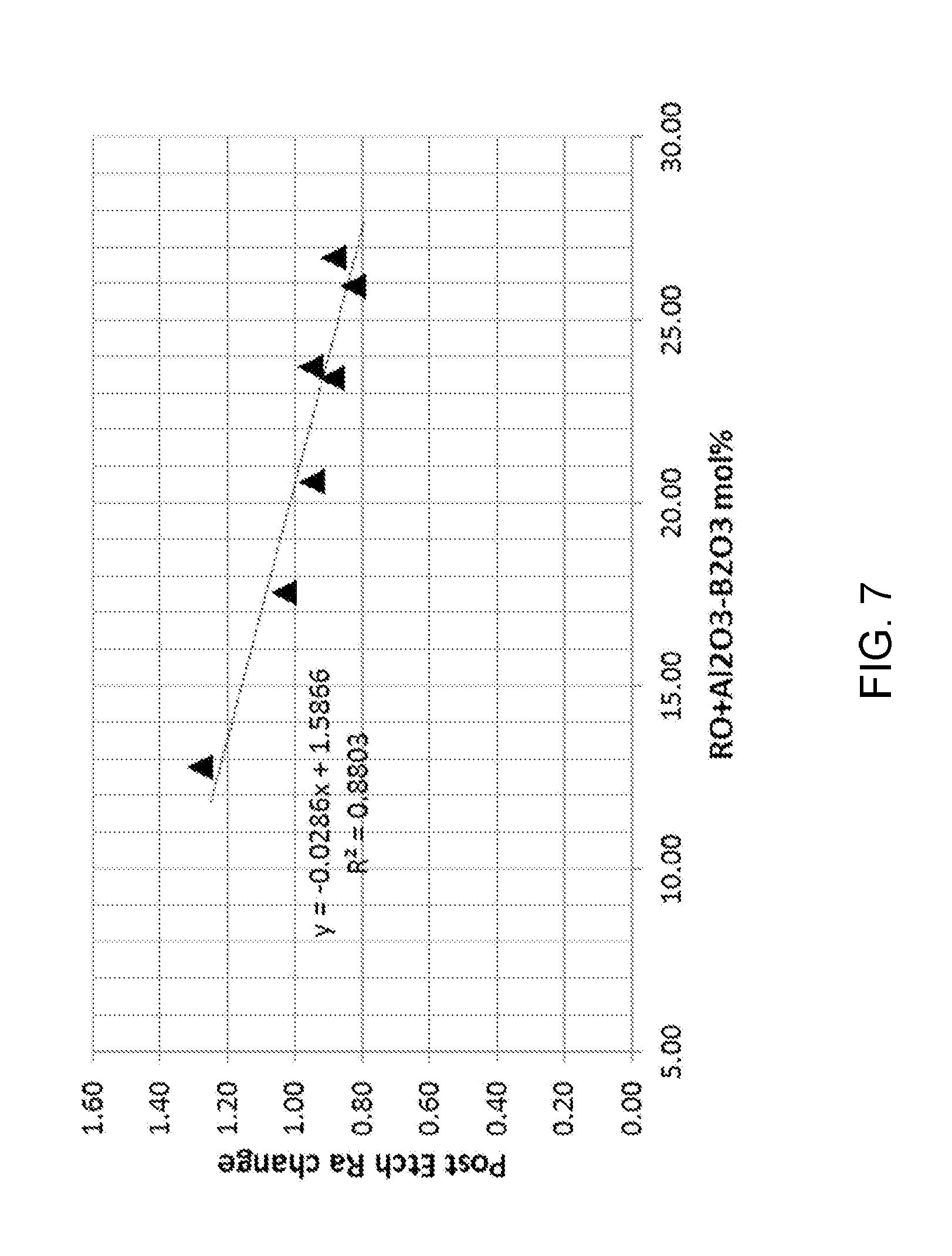
[0075] FIG. 6 shows a plot of post etch roughness (Ra) v. a glass composition parameter, RO+Al.sub.2O.sub.3-B.sub.2O.sub.3.
[0076] FIG. 7 shows an expanded portion of the plot of FIG. 6.
DETAILED DESCRIPTION
[0077] Embodiments of articles and methods of creating vias in substrates described herein allow for the preservation of surface roughness (Ra) of substrates. This allows the substrates, for example, to be removably bonded to carriers for further processing using Van der Waals bonding, which works best with low surface roughness substrates. The embodiments and methods disclosed herein may be used in other contexts where a low surface roughness etches surface is desirable.
[0078] An interposer may be used as an electrical interface in an electronic device, including devices having a radio frequency (RF) filter, to spread an electrical connection to a wider pitch or to reroute an electrical connection to a different electrical connection. Glass interposers, i.e., a glass substrate having vias through which electrical connections may be made, have become an attractive alternative to silicon and fiber reinforced polymers. This is due, in part, to the ability of glass to be formed in large thin sheets. However, with continuously thinner electronic devices, many applications require interposers to the have thicknesses of 300 .mu.m or less. Such thin glass can be difficult to handle in fabrication procedures because of the glass's fragility and lack of stiffness. To counteract a glass substrate's fragility and lack of stiffness, fabrication methods using a carrier to which the glass substrate is bonded are needed.
[0079] Van der Waals forces may be used to temporarily bond glass articles to carriers. The energy of the temporary bond is sufficient to survive flat panel fabrication, while remaining de-bondable. However, Van der Waals forces may produce weak bonds, if any, when the surface roughness (Ra) of the glass article is too high.
[0080] Typically, glass interposers require vias (holes) to be filled with electrically conductive material to provide electrical interfacing. A known method of creating vias in glass interposers is by creating a damage region through the thickness of the glass interposer and then submerging to substrate into an etchant. The etchant may then remove material from the damage region to enlarge the hole. However, the etching process may also remove material from both faces of the glass interposer as well as enlarging the hole. This etching may create a glass interposer surface roughness (Ra) outside of the range which Van der Waals bonds can be appropriately formed.
[0081] Glass compositions are disclosed herein which can be etched while preserving a low surface roughness suitable for Van der Waals bonding, and for other applications.
[0082] One way to reduce the post etch surface roughness of a glass substrate is to increase the alkali oxide (R.sub.2O) content of the glass composition. But, alkali oxides are undesirable for certain applications. For example, a glass interposer having a glass composition that includes too much alkali oxide may detrimentally affect or "poison" some of the devices typically placed near the interposer. So, using alkali oxides to achieve lower post etch surface roughness is unsuitable for some applications.
[0083] Another way to reduce the post etch surface roughness of a glass substrate is to increase the Al.sub.2O.sub.3 content of the glass composition. But, too much alumina can have undesirable effects, such as a too-large increase in the liquidus temperature of the glass composition. Alkali oxides may be used to lower the liquidus temperature. But, alkali oxides are undesirable for some applications as described above.
[0084] It has been unexpectedly and surprisingly found that, for low alkali oxide glasses, a specific glass content of SiO.sub.2, Al.sub.2O.sub.3, B.sub.2O.sub.3 and RO results in a low post etch surface roughness, where RO is the sum of the glass content of MgO+CaO+SrO+BaO+ZnO. In particular, the glass substrate comprises, in mol percent on an oxide basis: [0085] 65 mol %.ltoreq.SiO.sub.2.ltoreq.75 mol %; [0086] 7 mol %.ltoreq.Al.sub.2O.sub.3.ltoreq.15 mol %; [0087] 0.1 mol %.ltoreq.B.sub.2O.sub.3.ltoreq.2 mol %; [0088] wherein: [0089] 26.25 mol %.ltoreq.RO+Al.sub.2O.sub.3-B.sub.2O.sub.3; and [0090] 0 mol %.ltoreq.R.sub.2O.ltoreq.2 mol %. In these compositions, the RO content of the glass helps to lower post etch surface roughness without the undesirable effects of too much Al.sub.2O.sub.3 or too much R.sub.2O. By properly choosing the amounts of the glass components, a surprisingly low post etch surface roughness can be achieved for glass with a low alkali oxide content.
[0091] The articles disclosed herein may be used, for example, as an interposer in a semiconductor package, the articles having etched holes (e.g., vias) and surface attributes which allow for successful downstream processing including, but not limited to, via metallization and application of redistribution layers (RDL) for semiconductor devices, radio-frequency (RF) devices (e.g., antennae, switches, and the like), interposer devices, microelectronic devices, optoelectronic devices, microelectronic mechanical system (MEMS) devices and other applications where vias may be leveraged.
Substrates with Vias
[0092] FIG. 1 shows a cross section of an example article 100. Article 100 includes a substrate 110. Substrate 110 has a first surface 112 and a second surface 114, separated by a thickness T. A plurality of vias 124 extend from first surface 112 to second surface 114, i.e., vias 124 are through vias.
[0093] FIG. 2 shows a cross section of an example article 200. Article 200 includes a substrate 110. Substrate 110 has a first surface 112 and a second surface 114, separated by a thickness T. A plurality of vias 224 extend from first surface 112 towards second surface 114, without reaching second surface 114, i.e., vias 124 are blind vias.
[0094] A "via" as used herein refers to a hole or opening in a substrate. While FIGS. 1 and 2 show specific via configurations, various other via configurations may be used. By way of non-limiting example, vias having an hourglass shape, a barbell shape, beveled edges, or a variety of other geometries may be used instead of the cylindrical geometries shown in FIGS. 1 and 2. The via may be substantially cylindrical, for example having a waist (point along the via with the smallest diameter) with a diameter that is at least 70%, at least 75%, or at least 80% of the diameter of an opening of the via on the first or second surface. The via may extend all the way through the substrate, e.g. FIG. 1, or only partially through the substrate, e.g., FIG. 2. Other via geometries may be used.
[0095] For an application where low surface roughness is desired for removable bonding to a carrier, post-etch thickness T is typically in the range 50 .mu.m to 250 .mu.m. At higher thickness, substrate 110 may be sufficiently thick that a carrier is not needed. At lower thicknesses, substrate 110 may break in any event. Thickness T may be 150 .mu.m or less, 100 .mu.m, or 90 .mu.m to 110 .mu.m, which are thicknesses that balances the desire for thin devices against the desire for structural integrity and insulating properties. Thickness T may be 50 .mu.m, 100 .mu.m, 150 .mu.m, 200 .mu.m, 250 .mu.m, or any range having any two of the preceding values as endpoints. Other thicknesses may be used as well. For example, there may be applications for the low surface roughness substrates described herein other than removable bonding to a carrier. So, thickness T may depend on the application and is not necessarily limited by this disclosure.
[0096] First surface 112 and second surface 114 have a pre-etch surface roughness (Ra). As used herein, "surface roughness" refers to arithmetic mean surface roughness. The literature often uses the notation "Ra" to arithmetic mean surface roughness. Surface roughness Ra is defined as the arithmetic average of the differences between the local surface heights and the average surface height, and can be described by the following equation:
R a = 1 n i = 1 n y i ##EQU00001##
where y.sub.i is the local surface height relative to the average surface height. Surface roughness (Ra) may be measured and/or calculated from measurements using a variety of techniques. Unless otherwise specified, surface roughness as described herein is measured using a Veeco Dimension Icon atomic force microscope (AFM) with the following parameters: 1 Hz, 512 scans/line, and 2 micron image size.
Glass Composition
[0097] The glass compositions described herein are alkali free borosilicate glasses that generally include a combination of SiO.sub.2, Al.sub.2O.sub.3, and RO, where RO=MgO+CaO+SrO+BaO+ZnO. Alkali free means that the glasses include at most a small amount of alkali oxides (R.sub.2O), where R.sub.2O=Li.sub.2O+Na.sub.2O+K.sub.2O+Rb.sub.2O+Cs.sub.2O. In addition, the glass compositions described herein meet the condition 26.25.ltoreq.RO+Al.sub.2O.sub.3-B.sub.2O.sub.3. When etched with HF and similar etchants, the glass compositions exhibit a particularly low post-etch surface roughness for alkali free glass compositions.
[0098] In some embodiments, the glass compositions may include additional oxides such as P.sub.2O.sub.5, B.sub.2O.sub.3. These components may be added, for example, to modify the liquidus viscosity and/or improve the mechanical durability of the glass. In some embodiments the glass compositions may further one or more additional oxides such as, for example, SnO.sub.2, As.sub.2O.sub.3, Sb.sub.2O.sub.3 or the like, as described herein. These components may be added as fining agents.
[0099] Substrate 110 may be formed from various glass compositions. In a first embodiment, the glass substrate comprises, in mol percent on an oxide basis: [0100] 65 mol %.ltoreq.SiO.sub.2.ltoreq.75 mol %; [0101] 7 mol %.ltoreq.Al.sub.2O.sub.3.ltoreq.15 mol % [0102] 0.1 mol %.ltoreq.B.sub.2O.sub.3.ltoreq.2 mol %; [0103] 0 mol %.ltoreq.P.sub.2O.sub.5.ltoreq.2 mol %; [0104] 0 mol %.ltoreq.MgO.ltoreq.6 mol %; [0105] 0 mol %.ltoreq.ZnO.ltoreq.4 mol %; [0106] 0 mol %.ltoreq.CaO.ltoreq.6 mol %; [0107] 0 mol %.ltoreq.Sr.sub.0.ltoreq.10 mol %; [0108] 0 mol %.ltoreq.BaO.ltoreq.10 mol %; [0109] 0 mol %.ltoreq.SnO.sub.2.ltoreq.0.5 mol %; [0110] 0 mol %.ltoreq.As.sub.2O.sub.3.ltoreq.0.5 mol %; [0111] 0 mol %.ltoreq.Sb.sub.2O.sub.3.ltoreq.0.5 mol %; [0112] wherein: [0113] RO=MgO+CaO+SrO+BaO+ZnO; [0114] R.sub.2O=Li.sub.2O+Na.sub.2O+K.sub.2O+Rb.sub.2O+Cs.sub.2O [0115] 26.25 mol %.ltoreq.RO+Al.sub.2O.sub.3-B.sub.2O.sub.3; [0116] 0 mol %.ltoreq.R.sub.2O.ltoreq.2 mol %; and [0117] SiO.sub.2, Al.sub.2O.sub.3, B.sub.2O.sub.3, P.sub.2O.sub.5, Na.sub.2O, K.sub.2O, MgO, ZnO, CaO, SrO, BaO, SnO.sub.2, As.sub.2O.sub.3, Sb.sub.2O.sub.3, R.sub.2O, and RO represent the mol percents of the representative oxide components.
Silica
[0118] In the embodiments of the glass compositions described herein, SiO.sub.2 is the largest constituent of the composition and, as such, is the primary constituent of the resulting glass network. SiO.sub.2 enhances the chemical durability of the glass and, in particular, the resistance of the glass composition to decomposition in acid and the resistance of the glass composition to decomposition in water. If the content of SiO.sub.2 is too low, the chemical durability and chemical resistance of the glass may be reduced and the glass may be susceptible to corrosion. Accordingly, a high SiO.sub.2 concentration is generally desired. However, if the content of SiO.sub.2 is too high, the formability of the glass may be diminished as higher concentrations of SiO.sub.2 increase the difficulty of melting the glass which, in turn, adversely impacts the formability of the glass. In the first embodiment, the silica content of substrate 110 is 65 mol %.ltoreq.SiO.sub.2.ltoreq.75 mol %. In a tenth embodiment, 69 mol %.ltoreq.SiO.sub.2.ltoreq.72 mol %. The SiO.sub.2 content may be 65, 66, 67, 68, 69, 70, 71, 72, 73, 74 or 75 mol %, or any range having any two of the preceding values as endpoints.
[0119] Many methods of forming vias in glass involve the use of acid to etch the glass. For example, one method involves forming a damage track through the glass with a laser, and exposing the glass to acid. The acid permeates the damage track, removing the glass from the volume of the damage track. But, the acid may also etch and remove undamaged regions of the glass. A high silica content helps slow this etching of undamaged regions, which may be desirable.
Al.sub.2O.sub.3
[0120] The glass compositions described herein further include Al.sub.2O.sub.3. Al.sub.2O.sub.3, in conjunction with alkaline earth oxides and ZnO (RO) present in the glass compositions, leads to a low surface roughness glass surface after etching with etchants such as HF. Al.sub.2O.sub.3 may also increase the hardness and damage resistance of the glass. However, the liquidus viscosity of the glass decreases with increasing concentration of the Al.sub.2O.sub.3 in the glass compositions. If the concentration of Al.sub.2O.sub.3 in the glass compositions is too great, the liquidus viscosity of the glass composition decreases, which may cause the glass composition to crystallize during production in a fusion downdraw process. In addition, including too much Al.sub.2O.sub.3 may make it difficult to have a desirably high SiO.sub.2 content while also including all other desirable glass components. In the first embodiment, the Al.sub.2O.sub.3 content of substrate 110 is 7 mol %.ltoreq.Al.sub.2O.sub.3.ltoreq.15 mol %. The Al.sub.2O.sub.3 content may be 7, 8, 9, 10, 11, 12, 13, 14 or 15 mol %, or any range having any two of the preceding values as endpoints.
RO
[0121] The glass compositions described herein further include alkaline earth oxides and ZnO. Alkaline earth oxides include MgO, CaO, SrO, and BaO. ZnO, while technically not an alkaline earth oxide, is believed to have a similar effect on the glass composition for purposes of this disclosure. "RO" is used to refer collectively to MgO, CaO, SrO, BaO and ZnO. And, the RO content of the glass composition is the sum of the glass content of MgO, CaO, SrO, BaO and ZnO, in mol %. Increasing the RO content is one way to decrease the post etch roughness of the glass surface after etching with etchants such as HF. And, the use of RO does not have the poisonous effect of R.sub.2O. In the first embodiment, 26.25 mol %.ltoreq.RO+Al.sub.2O.sub.3-B.sub.2O.sub.3. Because the maximum amount of Al.sub.2O.sub.3 is 15 mol %, this means that the RO content is at least 11.25 mol %. In some embodiments, the parameter RO+Al.sub.2O.sub.3-B.sub.2O.sub.3 is greater than or equal to 26.25, 26.5, 26.75 or 27.0 mol %. Even higher values for this parameter may be used. But, at values higher than 27.5 mol %, it is believed that the parameter may increase the coefficient of thermal expansion (CTE) of the material to undesirably high levels for some applications.
[0122] RO oxides are added to improve the melting properties of the glass composition during processing, while also adjusting properties of the glass such as coefficient of thermal expansion (CTE) and density to desirable values. Small amounts of CaO and MgO can help with glass melting and improve the glass liquidus viscosity. But, above 6 mol %, CaO and MgO can detrimentally affect glass liquidus performance, and lead to devitrification during glass melting. ZnO improves glass hardness and modulus. But, ZnO also increases glass density and, in amounts higher than 4 mol %, can deteriorate glass compaction. BaO and SrO are both good for glass formability and thermal stability. But, BaO and SrO are relatively expensive, and also increase glass density. For these reasons, BaO and SrO are not above 10 mol %.
[0123] BeO and RaO are also alkaline earth oxides that should affect glass properties in a way similar to the other RO. But, they are generally not deliberately included in glass compositions due to their high cost.
R.sub.2O
[0124] The amount of alkali oxides in the glass composition is minimized. Alkali oxides may include one or more of Li.sub.2O, Na.sub.2O, K.sub.2O, Rb.sub.2O, and Cs.sub.2O. "R.sub.2O" is used to generally refer to the alkali oxides. And, the R.sub.2O content of the glass composition is the sum of the glass content of Li.sub.2O, Na.sub.2O, K.sub.2O, Rb.sub.2O, and Cs.sub.2O, in mol %. Increasing the content of alkali oxides is one way to decrease the post etch roughness of the glass surface after etching with etchants such as HF, which is desirable. But, alkali oxides may have detrimental effects for some applications. For example, where a glass substrate is used to provide through glass vias (TGV), the presence of alkali oxides may poison the types of devices typically connected by the TGV. For one type of device where TGV shows promise, RF (radio frequency) devices such as RF antennae, the presence of R.sub.2O undesirably lowers the transmittance of the glass. High transmittance is desired for better signal transfer. In the first embodiment, the R.sub.2O content is 0 mol %.ltoreq.R.sub.2O.ltoreq.2 mol %. The R.sub.2O content may be 0 mol %.ltoreq.R.sub.2O.ltoreq.2 mol %, 0 mol %.ltoreq.R.sub.2O.ltoreq.1 mol %, or 0 mol %.ltoreq.R.sub.2O.ltoreq.0.5 mol %. In some embodiments, the glass composition is free of R.sub.2O--R.sub.2O may be present only in tramp amounts.
Other Components
[0125] The glass compositions may also include phosphorous oxide (P.sub.2O.sub.5). The presence of P.sub.2O.sub.5 increases the liquidus viscosity of the glass compositions by suppressing the crystallization of mullite in the glass compositions. The liquidus temperature of the glass compositions increases rapidly when the amount of Al.sub.2O.sub.3 exceeds the sum of the amounts of alkali oxides (R.sub.2O mol. %) and alkaline earth oxides (RO mol. %) in the glass composition by more than 2 mol. %, or even by more than 1 mol. %. This issue is particularly acute for the compositions described herein, which have a limited amount of R.sub.2O. When Al.sub.2O.sub.3 (mol. %) is greater than (R.sub.2O (mol. %)+RO (mol. %)) by more than 1 mol. %, the presence of P.sub.2O.sub.5 in the glass composition compensates for the excess Al.sub.2O.sub.3 by decreasing the liquidus temperature, thus, increasing the liquidus viscosity of the glass composition. In some embodiments, the glass compositions may have an amount of P.sub.2O.sub.5 sufficient to compensate for the excess Al.sub.2O.sub.3. For example, in some embodiments, the glass compositions may have an amount of P.sub.2O.sub.5 sufficient so that (Al.sub.2O.sub.3 (mol. %)-R.sub.2O (mol. %)-RO (mol. %)-P.sub.2O.sub.5 (mol. %)) is less than or equal to 2 or even less than or equal to 1. In some embodiments, the glass compositions do not include P.sub.2O.sub.5. In this case, it may be that the amounts of Al.sub.2O.sub.3 and RO are such that the liquidus temperature does not increase rapidly. Or, it may be that a higher liquidus temperature is tolerable for the application. But, if the P.sub.2O.sub.5 content of the glass is too high, it may result in undesirable compaction, which is permanent shrinkage of the glass when heated. Some via fill processes use temperatures of 600 C or higher, so compaction can be a serious issue. In the second embodiment, the P.sub.2O.sub.5 content is 0 mol %.ltoreq.P.sub.2O.sub.5.ltoreq.2 mol %. The P.sub.2O.sub.5 content may be 0, 1 or 2 mol %, or any range having any two of the preceding values as endpoints.
[0126] Boron oxide (B.sub.2O.sub.3) is a flux which may be added to glass compositions to reduce the viscosity of the glass at a given temperature (e.g., the temperature corresponding to the viscosity of 200 poise, at which glass is melted and which is usually the highest temperature in the glass melting furnace) thereby improving the quality and formability of the glass. The presence of B.sub.2O.sub.3 may also improve damage resistance of the glass made from the glass composition. In the first embodiment, the B.sub.2O.sub.3 content is 0.1 mol %.ltoreq.B.sub.2O.sub.3.ltoreq.2 mol %. As with P.sub.2O.sub.5, too much B.sub.2O.sub.3 may result in undesirable compaction if the glass is heated. The B.sub.2O.sub.3 content may be 0.1, 0.5, 1, 1.5 or 2 mol %, or any range having any two of the preceding values as endpoints.
[0127] In addition to the components described elsewhere, the glass compositions described herein may optionally further include one or more fining agents such as, for example, SnO.sub.2, As.sub.2O.sub.3 or Sb.sub.2O.sub.3 The fining agents may be included in the glass composition to minimize or eliminate bubbles in the glass composition during formation. However, the fining agents generally have low solubility in the glass composition. Thus, if the amount of fining agents in the glass composition is too great, devitrification of the fining agents may occur during fusion forming. And, fining agents may be relatively expensive. So, when fining agents are included, it is desirable to include them in the lowest amounts needed to achieve the desired result. When a fining agent is present in the glass composition, the fining agent may be present in an amount less than or equal to 0.5 mol. %, less than or equal to 0.2 mol. %, or even less than or equal to 0.1 mol. %. In the second embodiment, the SnO.sub.2 content is 0 mol %.ltoreq.SnO.sub.2.ltoreq.0.5 mol %. The SnO.sub.2 content may be 0, 0.1, 0.2, 0.3, 0.4, or 0.5 mol %, or any range having any two of the preceding values as endpoints. In the second embodiment, the As.sub.2O.sub.3 content is 0.ltoreq.As.sub.2O.sub.3.ltoreq.0.5 mol %. The As.sub.2O.sub.3 content may be 0, 0.1, 0.2, 0.3, 0.4, or 0.5 mol %, or any range having any two of the preceding values as endpoints. In the second embodiment, the Sb.sub.2O.sub.3 content is 0.ltoreq.Sb.sub.2O.sub.3.ltoreq.0.5 mol %. The Sb.sub.2O.sub.3 content may be 0, 0.1, 0.2, 0.3, 0.4, or 0.5 mol %, or any range having any two of the preceding values as endpoints.
[0128] The glass compositions may include less than 0.05 mol. % tramp compounds, such as manganese compounds, cerium compounds, halfnium compounds, or other compounds, that may make it into the glass composition as impurities in the metal oxides deliberately included in the composition. Tramp compounds may also enter the glass composition through contact with processing equipment, such as refractory components of a fusion downdraw forming process, or the like.
Creation of Vias in Substrates
[0129] FIG. 3 shows a flowchart of a process 300 for creating and subsequently processing article 100. Process 300 includes process 310, which includes steps for the creation of vias in a substrate to create article 100. Process 300 also includes process 350, which includes bonding article 100 to a carrier, performing additional processing, and debonding article 100 from the carrier.
[0130] Process 310 comprises, in order:
Step 312: Form damage regions in substrate Step 314: Etch damage regions to form via
[0131] Damage Region Formation
[0132] In step 310, damage regions 120 are formed in substrate 100. Damage regions 120 may be formed in the substrate 110 in a variety of ways.
[0133] In some embodiments, a high energy laser pulse may be applied to create damage regions 120 through the substrate 110. Damage regions 120 allows etchant to flow therein during downstream etching processes. In some embodiments, damage regions 120 may be a line of laser-induced damage formed by a pulsed laser. The pulsed laser may form the damage line by non-linear multi-photon absorption, for example. When subsequently etched, the rate of material removal within such a damage region 120 is faster than the rate of material removal outside damage region 120. Exemplary ways for performing the laser damage creation and subsequent etching are disclosed in U.S. Pat. No. 9,278,886 and U.S. Pub. No. 2015/0166395, each of which is hereby incorporated by reference in its entirety. In some embodiments, a laser may be used to form an ablated hole instead of damage regions, and the ablated hole may be widened by etching.
[0134] FIG. 4 shows a cross section of an example article after step 310, but before step 320. Damage regions 120 are formed in substrate 110. While FIG. 4 shows cylindrical damage regions 120 for purposes of illustration, damage regions 120 may have an arbitrary shape. Damage regions 120 may be smaller than the ultimately desired vias 124 to account for removal of material during etching.
[0135] Etching
[0136] In step 320, damage regions 120 are etched to form vias 124 (or vias with other geometries, for example vias 224). Etching processes may include submerging the glass article 100 in an etchant 180 bath. Additionally or alternatively, the etchant 180 may be sprayed onto the glass article 100. The etchant 180 may remove material of the substrate 110 to enlarge damage regions 120. Any suitable etchants and etching methods may be utilized. Non-limiting examples of etchants include strong mineral acids such as nitric acid, hydrochloric acid, acylic acid or phosphoric acid; fluorine containing etchants such as hydrofluoric acid, ammonium bifluoride, sodium fluoride, and the like; and mixtures thereof. In some embodiments, the etchant is hydrofluoric acid.
[0137] FIGS. 1 and 2 illustrate substrate 100 after etching has occurred for different via geometries.
[0138] The etching of step 320 may expose parts of substrate 100 other than damage regions 120 to etchant, including one or both first surface 112 and second surface 114. This exposure may lead to etching of these other parts, which can cause an increased surface roughness (Ra). When using conventional alkali-free glass materials for substrate 110, surface roughness (Ra) may be undesirably increased to values higher than 0.75 nm, or even higher than 1.0 nm. This high surface roughness may render substrate 100 unsuitable for the Van der Waals bonding process described below.
[0139] Unexpectedly, the alkali-free glass compositions described herein exhibit a low post-etch roughness, notwithstanding the absence or low amounts of alkali oxide in the compositions. This low post-etch roughness is suitable for the Van der Waals bonding process described below. And, because the glass compositions have a low alkali (R.sub.2O) content, they are particularly well suited for use in applications the presence of alkali may be undesirable or damaging to the final product. For example, a substrate 100 made from the compositions described herein may have first surface 112 and/or second surface 114 with a post-etch surface roughness (Ra) of 0.75 nm or less, 0.7 nm or less, 0.65 nm or less, 0.6 nm or less, 0.55 nm or less, or 0.5 nm or less. This low surface roughness may enable the use of the Van der Waals bonding process described below, even though the glass composition is low-alkali or alkali-free.
[0140] A glass surface that has been etched has distinctive structural characteristics, and one of skill in the art can tell from inspecting a glass surface whether that surface has been etched. Etching often changes the surface roughness of the glass. So, if one knows the source of the glass and the roughness of that source, a measurement of surface roughness can be used to determine whether the glass has been etched. In addition, etching generally results in differential removal of different materials in the glass. This differential removal can be detected by techniques such as electron probe microanalysis (EPMA).
Bonding and Post-Etch Processing
[0141] FIG. 3 also shows process 350, which is post-etch processing using a carrier. Process 350 comprises, in order:
Step 352: Bond article 100 to a carrier Step 354: Perform further processing Step 356: Debond article 100 from the carrier For example, substrate 110 may be destined for use as an interposer, and may be subjected to further processing steps (step 320) to impart additional interposer properties.
[0142] Glass interposers may be very thin (e.g., anywhere from less than 300 .mu.m to 700 .mu.m). Such thin material may be difficult to handle during fabrication procedures because of the fragility and lack of stiffness of the substrate 110. To counteract the fragility and lack of stiffness, it is desirable to removably bond (step 352) substrate 110 to a carrier 200 after vias 124 have been formed, so that damage to substrate 110 may be avoided during further processing (step 354).
[0143] Van der Waals Bonding
[0144] One exemplary method of removably bonding a substrate 110 to a carrier is by using Van der Waals bonding such as disclosed by U.S. patent Publication No. 2014/0170378, which is incorporated by reference in its entirety. For example, Van der Waals bonding may include disposing a surface of an article on a bonding surface of a carrier and raising a temperature of the article followed by cooling the article to room temperature. The result is the article and the carrier being removably bonded together. Van der Waals bonding is beneficial to downstream processing because of its ability to form bonds that are capable of withstanding processing (e.g., high temperature processing), while allowing the entire area of the substrate to be debonded (step 356) from the carrier 200 when desired, either all at once or in sections. After substrate 110 has been debonded, carrier 200 may be re-used for processing additional substrates.
[0145] The challenge of using Van der Waals surface bonding techniques for bonding substrates is that the roughness of the surfaces' being bonded together impacts the ability of the surfaces to be bonded. As a non-limiting example, surface roughness (Ra) greater than 0.75 nm or 1.0 nm may substantially prevent spontaneous bonding, result in weak bonding of the substrate 110 to the carrier 200. Weak bonding may permit liquids from one or more processes to infiltrate between the substrate 110 and the carrier 200, thereby leading to de-lamination or to process contamination as residue from one process may impact later processes. In the configuration shown in FIG. 5, the surface roughnesses (Ra) of second surface 114 and bonding surface 210 affects the ability of substrate 110 to bond to carrier 200.
[0146] FIG. 5 illustrates substrate 110 removably bonded to carrier 200. Second surface 114 of substrate 110 is bonded to bonding surface 210 of carrier 200.
[0147] Carrier
[0148] Carrier 200 may be of any suitable material, such as glass, for example. Carrier 200 need not be glass, but instead may be ceramic, glass-ceramic, or metal, for example. If made of glass, carrier 200 may be of any suitable composition including, but not limited to, aluminosilicate, borosilicate, aluminoborosilicate, soda lime silicate, and may be either alkali containing or alkali-free depending upon its ultimate application. Carrier 200 may have any suitable thickness. Carrier 200 may be made of one layer, as shown, or multiple layers (including multiple thin sheets) that are bonded together (e.g., by lamination). The coefficient of thermal expansion of the carrier 200 may be substantially matched with that of substrate 110 to prevent warping of substrate 110 or decoupling of substrate 110 from carrier 200 during processing at elevated temperatures. Carrier 200 is not necessarily exposed to the same etching process as substrate 110, because the purpose of 200 is to provide support to substrate 100 during post-etch processing-carrier 200 typically does not have vias, and need not be exposed to the etching processes used to create vias. So, bonding surface 210 of carrier 200 may have a lower surface roughness (Ra) than that of first surface 112 and second surface 114 of substrate 110, which are exposed to etchant.
[0149] When considering the ability to form a suitable Van der Waals bond, the surface roughness (Ra) of the substrate 110 is additive to the surface roughness of the carrier 200. For good Van der Waals bonding, the sum of the surface roughness of the carrier and the substrate should be 0.95 nm or less, and preferably 0.9 nm or less. Fusion drawn glass, which is among the lowest roughness glasses that may be obtained at reasonable cost, has a typical surface roughness of 0.2 nm to 0.4 nm. Fusion drawn glass with a surface roughness of 0.2 nm may be obtained by appropriately selecting the glass composition. So, it is recommended to select a carrier with a surface roughness as low as possible that may be achieved at reasonable cost, which at the present time, is about 0.2 nm. So, for Van der Waals bonding between a substrate and a carrier to work well, where the carrier has a surface roughness of about 0.2 nm, the surface roughness of the substrate should be 0.75 nm or less, and preferably 0.7 nm or less.
[0150] Further Processing
[0151] The further processing of step 354 may include steps such as applying alkaline cleaning solutions to the substrate 110, wet etching the substrate 110, polishing the substrate 110, metal plating the substrate 110, metal patterning the substrate 110 by wet etching, depositing material onto the substrate 110 by deposition, and annealing the substrate 110. If substrate 110 were not bonded to carrier 200, this robust further processing would likely damage substrate 110. But, because substrate 110 is bonded to carrier 200, this further processing is far less likely to damage substrate 110.
[0152] De-Bonding
[0153] Debonding may be accomplished by any suitable means. For example, a wedge may be used at an outer portion of the bonded substrate 110 and carrier 200 to initiate debonding, followed by peeling. Examples of suitable debonding techniques are described in PCT Publication WO 2017/127489, "Methods for Processing a Substrate."
Examples
[0154] The following Comparative Examples and Examples compare changes in surface roughness (Ra) as a result of acid etching.
[0155] Sixteen glass samples prepared by the fusion draw process were obtained. Each glass sample was 0.7 mm thick and did not have damage regions. The surface roughness (Ra) of each sample was measured prior to etching, as shown in Table 1. Unless otherwise specified, surface roughness in the examples was measured by a Veeco Dimension ICON AFM with the following parameters: 1 Hz, 512 scans/line, and 2 micron image size.
[0156] Table 1 and FIG. 6 show the parameter RO+Al.sub.2O.sub.3-B.sub.2O.sub.3 for each of the glass samples. Samples 1 through 7 also met the criteria: wherein the glass substrate comprises, in mol percent on an oxide basis: [0157] 65 mol %.ltoreq.SiO.sub.2.ltoreq.75 mol %; [0158] 7 mol %.ltoreq.Al.sub.2O.sub.3.ltoreq.15 mol %; [0159] 0.1 mol %.ltoreq.B.sub.2O.sub.3.ltoreq.2 mol %; [0160] 0 mol %.ltoreq.P.sub.2O.sub.5.ltoreq.2 mol %; [0161] 0 mol %.ltoreq.MgO.ltoreq.6 mol %; [0162] 0 mol %.ltoreq.ZnO.ltoreq.4 mol %; [0163] 0 mol %.ltoreq.CaO.ltoreq.6 mol %; [0164] 0 mol %.ltoreq.SrO.ltoreq.10 mol %; [0165] 0 mol %.ltoreq.BaO.ltoreq.10 mol %; [0166] 0 mol %.ltoreq.SnO.sub.2.ltoreq.0.5 mol %; [0167] 0 mol %.ltoreq.As.sub.2O.sub.3.ltoreq.0.5 mol %; [0168] 0 mol %.ltoreq.Sb.sub.2O.sub.3.ltoreq.0.5 mol %; [0169] wherein: [0170] RO=MgO+CaO+SrO+BaO+ZnO; [0171] R.sub.2O=Li.sub.2O+Na.sub.2O+K.sub.2O+Rb.sub.2O+Cs.sub.2O [0172] 0 mol %.ltoreq.R.sub.2O.ltoreq.2 mol %; and [0173] P.sub.2O.sub.5, Na.sub.2O, K.sub.2O, SnO.sub.2, As.sub.2O.sub.3, Sb.sub.2O.sub.3, represent the mol percents of the representative oxide components.
[0174] None of the samples tested satisfied the criteria: 26.25 mol %.ltoreq.RO+Al.sub.2O.sub.3-B.sub.2O.sub.3. But, the tested samples do show the trend in post-HF surface roughess that occurs as the parameter 26.25 mol %.ltoreq.RO+Al.sub.2O.sub.3-B.sub.2O.sub.3 is varied.
[0175] The glass samples were then cleaned with a high pH detergent wash (2% Semiclean-KG, 60.degree. C. for 4 minutes) and a deionized (DI) water rinse. The cleaned glasses were etched in 2.5 wt % HF (or 1.45M HF) to remove 5 microns of glass surface. The etched glasses were cleaned by a second high pH detergent wash and DI water rinse.
[0176] After etching and cleaning, the surface roughness of each sample was measured again, as shown in Table 1.
TABLE-US-00001 TABLE 1 RO + Al.sub.2O.sub.3 - B.sub.2O.sub.3 Pre-etch R.sub.a Post-etch R.sub.a Sample (mol %) (nm) (nm) 1 17.57 0.34 1.03 2 20.59 0.34 0.95 3 12.80 0.37 1.28 4 23.73 0.30 0.95 5 23.42 0.29 0.89 6 25.94 0.28 0.82 7 26.70 0.54 0.88
[0177] Compositions that satisfy the criteria 26.25 mol %.ltoreq.RO+Al.sub.2O.sub.3-B.sub.2O.sub.3 include the following:
TABLE-US-00002 TABLE 2 RO + Al.sub.2O.sub.3--B.sub.2O.sub.3 Sample SiO.sub.2 B.sub.2O.sub.3 Al.sub.2O.sub.3 MgO CaO SrO SnO.sub.2 BaO ZnO mol % A 69.0 1.8 13.3 5.0 5.3 1.5 0.1 3.0 1.0 27.3 B 68.0 1.0 15.0 4.0 5.0 2.0 0.1 2.9 2.0 29.9 C 68.0 1.0 15.0 4.0 5.0 3.0 0.1 3.9 1.0 30.9
The compositions of Table 2 are provided as prophetic examples. The values in Table 2 are in mol %.
CONCLUSION
[0178] It should be understood that embodiments described herein provide for forming vias in substrates without substantially increasing the surface roughness (Ra) of the substrate. By preserving the low surface roughness of the substrate during via formation, the substrate may be removably bonded to a carrier for further processing. After processing, the substrate may be removed from the carrier, such that the carrier may be reused for processing further substrates. Furthermore, the through vias may be made substantially cylindrical because they may be etched from both ends.
[0179] While specific procedures involving the etching of vias and the use of a carrier are described herein, the glass compositions described herein may be advantageously used with a variety of different processes involving etching where a low post-etch surface roughness is desired.
[0180] As used herein, the term "about" means that amounts, sizes, formulations, parameters, and other quantities and characteristics are not and need not be exact, but may be approximate and/or larger or smaller, as desired, reflecting tolerances, conversion factors, rounding off, measurement error and the like, and other factors known to those of skill in the art. When the term "about" is used in describing a value or an end-point of a range, the specific value or end-point referred to is included. Whether or not a numerical value or end-point of a range in the specification recites "about," two embodiments are described: one modified by "about," and one not modified by "about." It will be further understood that the endpoints of each of the ranges are significant both in relation to the other endpoint, and independently of the other endpoint.
[0181] The terms "free" and "substantially free," when used to describe the concentration and/or absence of a particular constituent component in a glass composition, means that the constituent component is not intentionally added to the glass composition. However, the glass composition may contain traces of the constituent component as a contaminant or tramp in amounts of less than 0.05 mol. %.
[0182] The term "tramp," when used to describe a particular constituent component in a glass composition, refers to a constituent component that is not intentionally added to the glass composition and is present in amounts less than 0.05 mol. %. Tramp components may be unintentionally added to the glass composition as an impurity in another constituent component or through migration of the tramp component into the composition during processing of the glass composition.
[0183] The embodiments illustrated in the figures are not necessarily to scale. Relative sizes and widths may have been selected for ease of illustration.
[0184] It will be apparent to those skilled in the art that various modifications and variations can be made to the embodiments described herein without departing from the spirit and scope of the claimed subject matter. Thus it is intended that the specification cover the modifications and variations of the various embodiments described herein provided such modification and variations come within the scope of the appended claims and their equivalents.
* * * * *
D00000
D00001
D00002
D00003
D00004
D00005
D00006
D00007
XML
uspto.report is an independent third-party trademark research tool that is not affiliated, endorsed, or sponsored by the United States Patent and Trademark Office (USPTO) or any other governmental organization. The information provided by uspto.report is based on publicly available data at the time of writing and is intended for informational purposes only.
While we strive to provide accurate and up-to-date information, we do not guarantee the accuracy, completeness, reliability, or suitability of the information displayed on this site. The use of this site is at your own risk. Any reliance you place on such information is therefore strictly at your own risk.
All official trademark data, including owner information, should be verified by visiting the official USPTO website at www.uspto.gov. This site is not intended to replace professional legal advice and should not be used as a substitute for consulting with a legal professional who is knowledgeable about trademark law.