Fillable Vaporizer Cartridge and Method of Filling
Atkins; Ariel ; et al.
U.S. patent application number 16/404693 was filed with the patent office on 2019-08-22 for fillable vaporizer cartridge and method of filling. The applicant listed for this patent is JUUL Labs, Inc.. Invention is credited to Ariel Atkins, Steven Christensen, Aaron Keller, James Monsees.
| Application Number | 20190256231 16/404693 |
| Document ID | / |
| Family ID | 59564062 |
| Filed Date | 2019-08-22 |


| United States Patent Application | 20190256231 |
| Kind Code | A1 |
| Atkins; Ariel ; et al. | August 22, 2019 |
Fillable Vaporizer Cartridge and Method of Filling
Abstract
Vaporizer device cartridges are provided. In some implementations, a cartridge comprises a storage compartment having first and second opposing ends, a sealing material sealing the second end, and a wick positioned proximate to the first end. The storage compartment is configured to hold a liquid vaporizable material. The sealing material is configured for insertion of a needle through the sealing material for dispensing the liquid vaporizable material into the storage compartment. The wick comprises opposing ends in communication with the storage compartment and is configured to allow a volume of air to exit the storage compartment through the wick when the storage compartment is being filled with the liquid vaporizable material.
| Inventors: | Atkins; Ariel; (San Francisco, CA) ; Christensen; Steven; (San Mateo, CA) ; Keller; Aaron; (Santa Rosa, CA) ; Monsees; James; (San Francisco, CA) | ||||||||||
| Applicant: |
|
||||||||||
|---|---|---|---|---|---|---|---|---|---|---|---|
| Family ID: | 59564062 | ||||||||||
| Appl. No.: | 16/404693 | ||||||||||
| Filed: | May 6, 2019 |
Related U.S. Patent Documents
| Application Number | Filing Date | Patent Number | ||
|---|---|---|---|---|
| 15430284 | Feb 10, 2017 | 10279934 | ||
| 16404693 | ||||
| 62294285 | Feb 11, 2016 | |||
| Current U.S. Class: | 1/1 |
| Current CPC Class: | A24F 47/008 20130101; A61M 15/06 20130101; A61M 11/042 20140204; B65B 3/14 20130101; B65B 3/003 20130101; B65B 25/041 20130101; A61M 2209/045 20130101; B65B 3/18 20130101 |
| International Class: | B65B 3/00 20060101 B65B003/00; A24F 47/00 20060101 A24F047/00; B65B 3/14 20060101 B65B003/14; B65B 3/18 20060101 B65B003/18 |
Claims
1.-17. (canceled)
18. A vaporizer device cartridge, comprising: a storage compartment having a first end and a second end opposite the first end, the storage compartment configured to hold a liquid vaporizable material; a sealing material sealing the second end, the sealing material configured for insertion of a needle through the sealing material for dispensing the liquid vaporizable material into the storage compartment; and a wick positioned proximate to the first end, the wick comprising opposing ends in communication with the storage compartment, the wick configured to allow a volume of air to exit the storage compartment through the wick when the storage compartment is being filled with the liquid vaporizable material.
Description
CROSS REFERENCE TO RELATED APPLICATIONS
[0001] This application claims priority to U.S. provisional application no. 62/294,285, titled "FILLABLE ELECTRONIC CIGARETTE CARTRIDGE AND METHOD OF FILLING," filed on Feb. 11, 2016 which is herein incorporated by reference in its entirety.
[0002] This application may be related to or may be used with the inventions in one or more of the following patent applications: U.S. patent application Ser. No. 14/578,193, filed on Dec. 19, 2014 and titled "METHOD AND SYSTEM FOR VAPORIZATION OF A SUBSTANCE"; U.S. patent application Ser. No. 14/625,042, filed on Feb. 18, 2015, and titled "AEROSOL DEVICES AND METHODS FOR INHALING A SUBSTANCE AND USES THEREOF"; U.S. patent application Ser. No. 13/837,438, filed on Mar. 15, 2013, and titled "LOW TEMPERATURE ELECTRONIC VAPORIZATION DEVICE AND METHODS"; U.S. patent application Ser. No. 14/271,071, filed on May 6, 2014, and titled "NICOTINE SALT FORMULATIONS FOR AEROSOL DEVICES AND METHODS THEREOF"; U.S. patent application Ser. No. 14/304,847, filed on Jun. 13, 2014, and titled "MULTIPLE HEATING ELEMENTS WITH SEPARATE VAPORIZABLE MATERIALS IN AN ELECTRIC VAPORIZATION DEVICE"; U.S. patent application Ser. No. 14/461,284, filed on Aug. 15, 2014 and titled "METHODS AND DEVICES FOR DELIVERING AND MONITORING OF TOBACCO, NICOTINE, OR OTHER SUBSTANCES"; U.S. patent application Ser. No. 14/581,666, filed on Dec. 23, 2014, and titled "VAPORIZATION DEVICE SYSTEMS AND METHODS"; PCT Patent Application No. PCT/US2015/031152, filed on May 15, 2015, and titled "SYSTEMS AND METHODS FOR AEROSOLIZING A SMOKEABLE MATERIAL"; PCT Patent Application No. PCT/US2014/064690, filed on Nov. 7, 2014, and titled "NICOTINE LIQUID FORMULATIONS FOR AEROSOL DEVICES AND METHODS THEREOF"; U.S. patent application Ser. No. 14/960,259, filed on Dec. 4, 2015, and titled "CALIBRATED DOSE CONTROL". Each of these applications is herein incorporated by reference in their entirety.
INCORPORATION BY REFERENCE
[0003] All publications and patent applications mentioned in this specification are herein incorporated by reference in their entirety to the same extent as if each individual publication or patent application was specifically and individually indicated to be incorporated by reference.
FIELD
[0004] This invention relates to electronic cigarette cartridges, and in particular to cartridges and methods of filling of electronic cartridges.
BACKGROUND
[0005] Electronic cigarettes and cartridges that contain their vaporizable liquid in a "tank" structure or reservoir have performance and usability advantages over those which hold the liquid inside of a sponge or other medium. Unfortunately, tank-type cigarettes and cartridges have some unique difficulties associated with filling them. These problems are particularly acute because of the need for a porous wick that is in contact with the tank in the cartridge and/or electronic cigarette.
[0006] For example, tank-type cartridges may leak when subjected to a change in atmospheric pressure (such as may occur during air shipment), which can cause liquid to leak through the necessary porous wick, due to expansion of any captive air. If the cartridge could be filled completely with no captive air, this issue can be eliminated, at least at the time of initial shipment. As a result there is significant incentive to attempt to fill the cartridge as completely as possible.
[0007] There are currently two main approaches to filling a tank-type cartridge. The first approach is to make use of one or more elastomeric "plug" components that are removed and leave sufficient clearance at the time of filling that any air that is captured in the cartridge is able to freely vent through the same hole or holes that liquid is being added to. A secondary operation is required to install the plug, along with in many cases an additional cosmetic part that conceals the plug.
[0008] Unfortunately, the approach of filling with a plug part removed has a few problems. First, it requires that the cartridge be partially disassembled at the time of filling. This can result in supply chain complexity of shipping components separately as well as additional costs associated with the additional capping operation, especially if the cartridges are assembled in different locations as is often the case where it may be cheaper to manufacture in a first location and assemble in a second location. Second, a plug may potentially take up volume in the cartridge, and finally, inserting the cap my itself displace fluid and introduce air; inserting the plug may force the displaced volume of liquid through the porous wick to the outside of the tank area. The non-zero time between the filling operation and the capping operation can create a potential failure mode where liquid is allowed to slowly leak out through the wick without the negative backpressure provided by the sealed reservoir. The amount of liquid that can leak through during even a controlled time frame is a function of the viscosity of the liquid (which can be variable based on the liquid used) and therefore can be difficult to control.
[0009] The second approach, discussed in patent application no. WO2015028815 A1, is to use a sufficiently large elastomeric component of sufficiently low durometer that it can be pierced simultaneously by two hypodermic style needles whose pierce sites will reseal sufficiently after the needles are removed. This approach assumes an effective seal between the elastomeric component and the filling needle but requires a second, venting needle. One needle is described as being the inlet for liquid into the interior of the cartridge, while the other for the evacuation of the air that is inside the cartridge before filling. This approach allows the cartridges to be fully assembled at the time of fill.
[0010] Although this two needle approach may alleviate the need to perform a separate capping operation, it also has issues in terms of its ability to fill the cartridge completely and with a precise volume of liquid. Each pierce location is a potential failure site in the final product, and thus using a secondary vent pierce site doubles the chance of a problem with the final product and during the piercing process. In addition, if passive venting is chosen through the second needle, the level of fill must be sufficiently low to prevent liquid ever reaching the second needle, because although air can easily vent through the small diameter needle; liquid in the needle constitutes a significant blockage. Once liquid enters the second needle, air may no longer flow, even if still trapped within the electronic cigarette or cartridge reservoir. If active venting is chosen, there is a similar risk that the vacuum will pull liquid out of the cartridge, causing waste and introducing additional randomness to the final fill volume.
[0011] Finally, in all cases the secondary vent pierce limits how full the container can be filled since the needle has to pierce sufficiently deeply to ensure that it's opening is fully below the surface of the elastomeric component, which inherently means that there is some cavity of air left above it that can never be displaced. This issue persists even if a production method is created that can tolerate the liquid front reaching all the way to the vent location. Once the liquid front reaches the vent location any incremental liquid added to the system either gets forced through the vents or through the porous wick to the outside of the tank.
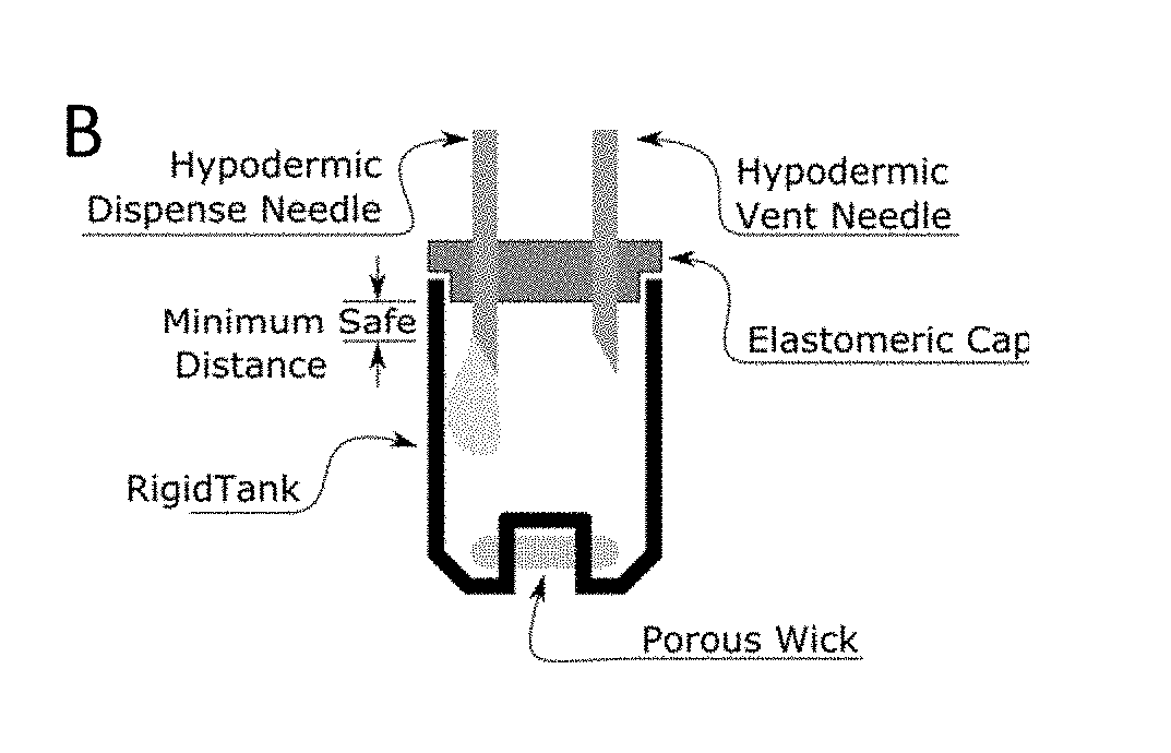
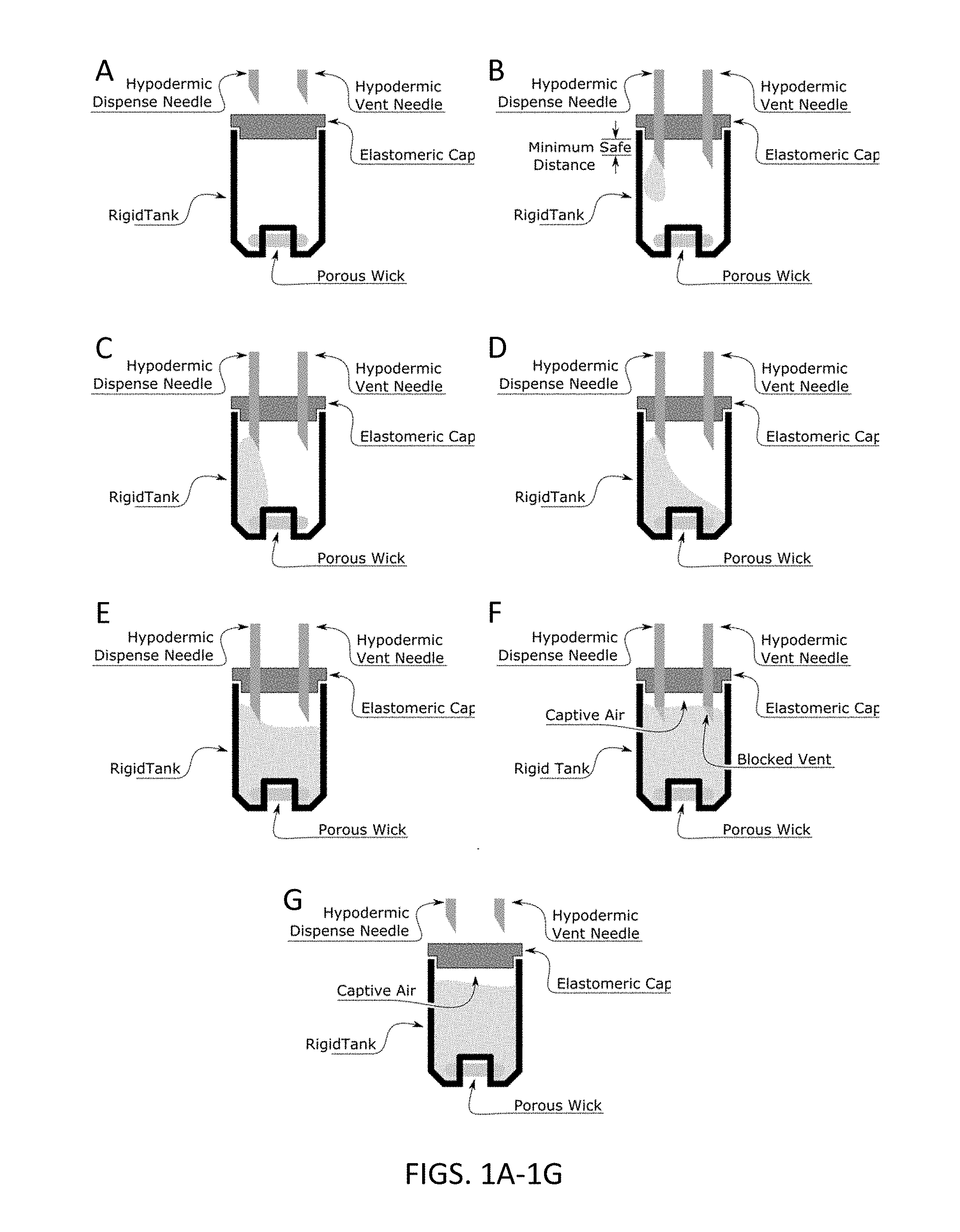
[0012] For example, FIGS. 1A-1G illustrate the use of the current two-needle approach and its shortcomings. In this example, the cartridge includes an elastomeric cap, and is preassembled with the wick, polymeric reservoir (rigid tank), and elastomeric (piercible) resealable cap. In FIG. 1A the assembled cartridge is ready to be filled by receiving the needles. In FIG. 1B the needle pierces the elastomeric cap to a distance that is large enough to ensure that the needle opening is exposed and open within the cartridge, then begins to fill. In FIG. 1C, the front of liquid being filled reaches one end of the cartridge and one side of the wick. In FIG. 1D the liquid front has occluded both sides of the porous wick. In FIG. 1E the liquid front has risen until it is nearly at the vent needle. This may be an ideal time to stop if (e.g., passive filling) the needle will clog and stop passing air once fluid contacts it (e.g., cannot tolerate liquid in the vent line). In FIG. 1F the liquid front has occluded all of the vent locations, and any incremental liquid pumped into the cartridge past this point (even with active venting through the vent needle) will either pass through the vent needle or leak out of the porous wick. No additional air can be displaced. Finally in FIG. 1G, once no more liquid can be added to the system, the needles are retracted and the filling is complete, leaving a substantial amount of captive air.
[0013] Thus, there is a need for methods and apparatuses (e.g., cartridges, filling devices and the like) for filling electronic cigarette and/or cartridge reservoirs so that they do not trap any air within the otherwise sealed reservoir, and particularly in reservoirs including a porous wick. Described herein are methods and apparatuses to address this need.
SUMMARY OF THE DISCLOSURE
[0014] Described herein are apparatuses including tanks to be filled with a vaporizable liquid and methods of filing them. Also described are systems for filling one or a plurality of cartridges having tanks without entrapping air within the tank volume. For example, described herein are methods of filling a tank volume of a cartridge for an electronic cigarette from a bottom or side surface opposite a wick so that the wick remains at least partially dry and can vent air during filling until the tank volume is full.
[0015] A method of filling a tank volume of an electronic cigarette cartridge with a liquid vaporizable material, wherein the cartridge includes a porous wick at a first end of the tank volume, may include: positioning the cartridge on a surface so that the porous wick is positioned on a top or side surface; inserting a needle into the tank volume from a bottom or side surface, opposite from the porous wick; injecting a vaporizable liquid into the tank volume; and venting air out of the tank through the porous wick until the tank volume is full of the vaporizable liquid and no air is entrapped within the tank volume.
[0016] A method of filling a tank volume of an electronic cigarette cartridge with a liquid vaporizable material, wherein the cartridge includes a porous wick at a first end of the tank volume, may include: positioning the cartridge on a surface so that the porous wick is oriented on a top opposite from the surface; inserting a needle into the tank volume from a bottom of the cartridge, opposite from the porous wick; injecting a vaporizable liquid into the tank volume through the needle; and venting air out of the tank through the porous wick as the tank volume fills, until the tank volume is full of the vaporizable liquid and no air is entrapped within the tank volume.
[0017] A method of filling a tank volume of an electronic cigarette cartridge with a liquid vaporizable material, wherein the cartridge includes a porous wick at a first end of the tank volume, may include: positioning the cartridge on a surface so that the porous wick is positioned on a side above the surface; inserting a needle into the tank volume from a side of the cartridge that is opposite from the porous wick; injecting a vaporizable liquid into the tank volume through the needle; and venting air out of the tank through the porous wick as the tank volume fills, until the tank volume is full of the vaporizable liquid and no air is entrapped within the tank volume.
[0018] In any of the methods described herein, the cartridge may be positioned flat against the surface, on a long side, on a short side, or on its top. In general the cartridges described herein may be rectangular in outer cross-section.
[0019] Any appropriate needle may be used. For example, the needle may have a beveled distal tip and a front-facing aperture. The needle may have a beveled distal tip and one or more side-facing aperture(s). The needle may be blunt.
[0020] Inserting the needle may include inserting through a septum, such as an elastomeric top or side. In some variations, inserting the needle may include inserting the needle through a pre-cut port or valve.
[0021] In any of the methods described herein, the temperature of the material being filled and/or the temperature of the filling device (including the needle(s), surface, stage or stand onto which the cartridges are held) or all or part of the cartridge itself (including just the tank and any internal components of the tank) may regulated by heating and/or warming. For example, when filling with a viscous material, the material may be warmed to lower the viscosity and/or cooled within the tank to increase the viscosity.
[0022] In general, the vaporizable liquid may comprise any appropriate material, including nicotine solutions (e.g., the vaporizable liquid may be a nicotine salt in an aqueous solution), a cannabis liquid (e.g., including a viscous cannabis-containing material), or any other pharmaceutical material. For example, the vaporizable material may contain a medicinal compound as an active ingredient. The medicinal compounds that are active ingredients for vaporization with the electronic vaporizer device utilizing the method herein, include drugs that can be heated without combustion to vaporization for inhalation delivery at a temperature range of, e.g., about 100.degree. C. (e.g., for water-based carriers, e.g., about 100.degree. C. , 105.degree. C., 110.degree. C., 120.degree. C., 130.degree. C., 140.degree. C., 150.degree. C., 160.degree. C., 170.degree. C., etc.; for ethanol-based formulations, e.g., about 50.degree. C., about 60.degree. C., about 70.degree. C., about 80.degree. C., etc.) to about (e.g., below) the temperature at which the active ingredient thermally decomposes (e.g., less than about 150.degree. C., 160.degree. C., 170.degree. C., 180.degree. C., 190.degree. C., 200.degree. C., 210.degree. C., 220.degree. C., 230.degree. C., 240.degree. C., 250.degree. C., 260.degree. C., 270.degree. C., 280.degree. C., 290.degree. C., 300.degree. C., etc.). In certain embodiments, the drugs can be neat or are solubilized in a pharmaceutically acceptable solvent. In certain embodiments, the drugs can include over the counter (OTC) substances as aides for various ailments; wherein said drugs can include known respiratory aides for asthma or chronic obstructive pulmonary disease (COPD). The vaporizable materials that are active ingredients for vaporization with the device(s) herein described, can include drugs that can be heated to vaporization for inhalation delivery, without combustion; wherein said drugs can include over the counter (OTC) substances from the group comprising upper respiratory aides (like cetirizine), analgesics and internal medication aides (like ibuprofen, naproxen), heartburn aides (like omeprazole), sleeping aides (like doxylamine, diphenhydramine, melatonin), or motion sickness aides (like meclizine). In certain embodiments, the vaporizable material can contain respiratory aides for asthma or chronic obstructive pulmonary disease (COPD) such as short acting beta-agonist (like albuterol, levalbuterol, pirbuterol), long acting beta-agonist (like salmeterol, formoterol), anti-cholinergics (like atropine sulfate, ipratropium bromide), leukotriene modifiers (like montelukast, zafirlukast), cartico-steriods (like fluticasone, budesonide, mometasone), theophylline (like theophylline), or combination corticosteroid and beta agonist, long lasting (fluticasone and salmeterol, budesonide and formoterol, mometasone and formoterol). In certain embodiments, the vaporizable material can contain botanicals and/or nutraceuticals such as tea (polyphenols, flavonoids, green tea catechins +/- caffeine); horehound (phenol flavonoid glycosides, labdane diterpenoids, yohimbe, cranberry/grape(proanthocyanidins), black cohosh (terpene glycoside fraction (actine/cimifugoside), flax seed (omega fatty acids), echinacea (echinacoside), valerian (alkaloids, gabapentin, isovaleric acid, terpenes), senna (senna cglycosides), cinnamon (cinnamaldehyde, phenols, terpenes), vitamin D, saw palmetto (fatty acids), or caffeine. In certain embodiments, the vaporizable material is soluble to at least fifty percent by weight in any suitable carrier solvent such as glycols (such as propylene glycol and vegetable glycerin), ethylene glycol, dipropylene glycol, trimethylene glycol, ethanol, and combinations thereof. In certain embodiments, the medicinal compound is terpinolene. In certain embodiments, the medicinal compound is Linalool. In certain embodiments, the medicinal compound is phytol. In certain embodiments, the medicinal compound is beta myrcene. In certain embodiments, the medicinal compound is citronellol. In certain embodiments, the medicinal compound is caryophyllene oxide. In certain embodiments, the medicinal compound is alpha pinene. In certain embodiments, the medicinal compound is limonene. In certain embodiments, the medicinal compound is beta caryophyllene. In certain embodiments, the medicinal compound is humulene. In certain embodiments, the vaporizable material is an essential oil.
[0023] In any of these variations, the vaporizable liquid may be injected into the tank volume at any appropriate rate. For example, the vaporizable liquid may be injected into the tank volume at between about 0.1 ml/sec and 5 ml/sec, 0.5 ml/sec and 2 ml/sec, about 1 ml/sec, etc. (e.g., ata rate between a lower value in ml/sec of 0.05, 0.06, 0.07, 0.08, 0.09, 0.1, 0.2, 0.3, 0.4, 0.5, 0.6, 0.7, 0.8, 0.9 1.0, 1.1, 1.2, 1.3, 1.4, 1.5, 1.6, 1.7, 1.8, 1.9, 2, 3, 4, 5, 6, 7, 8, 9, 10, 12, 15, etc. and an upper value in ml/sec of 0.5, 0.6, 0.7, 0.8, 0.9 1.0, 1.1, 1.2, 1.3, 1.4, 1.5, 1.6, 1.7, 1.8, 1.9, 2, 3, 4, 5, 6, 7, 8, 9, 10, 12, 15, 20, etc. where the lower value is always less than the upper value).
[0024] In any of these variations, and particularly when the cartridge is oriented on its side and injected from the side, it may be beneficial for the tank volume to include one or more obstructions within the tank volume. The obstruction (e.g., central tube or cannula passing through the tank volume) may form sub-regions within the tank volume the preferentially fill first, without entrapping air, and allow the tank volume to be filled at high rates (e.g., between about 0.5 ml/sec and 2 ml/sec, greater than 0.5 ml/sec, etc.) without entrapping air within the tank volume.
[0025] In general, any of these methods may include keeping at least a portion of the wick that is within the tank dry until there is no air entrapped within the tank volume.
[0026] Once the filling is complete, the needle may be withdrawn. In any of these methods the needle may be reoriented, including rotating and/or moving laterally (further into or partially out of the tank volume) during filling to direct the filling and prevent entrapment of air.
[0027] In any of these variations, the method may be done in parallel to simultaneously fill a large number of cartridges. For example, the method may include positioning a plurality of cartridges in parallel and concurrently inserting a plurality of needles into each of the cartridges, and concurrently injecting the vaporizable liquid into each of the cartridges.
BRIEF DESCRIPTION OF THE DRAWINGS
[0028] FIGS. 1A-1G illustrate a prior art method for filling a reservoir of an electronic cigarette cartridge which traps air within the cartridge.
[0029] FIG. 2 is an exploded view of one example of a cartridge, including a reservoir, for an electronic cigarette.
[0030] FIGS. 3A-3F illustrate a method filling a reservoir of a cartridge, similar to the cartridge shown in FIG. 2, of an electronic cigarette with a single needle.
[0031] FIGS. 4A-4H illustrate a method of filling a reservoir of a cartridge, similar to the cartridge shown in FIG. 2, of an electronic cigarette with a single needle.
[0032] FIGS. 5A and 5B illustrate side and top views, respectively, of one variation of a filling needle.
[0033] FIGS. 6A and 6B illustrate side and top views, respectively, of one variation of a filling.
[0034] FIGS. 7A and 7B illustrate side and top views, respectively, of one variation of a filling needle.
[0035] FIGS. 8A-8F illustrate a method of filling a reservoir of a cartridge, similar to the cartridge shown in FIG. 2, of an electronic cigarette with a single needle.
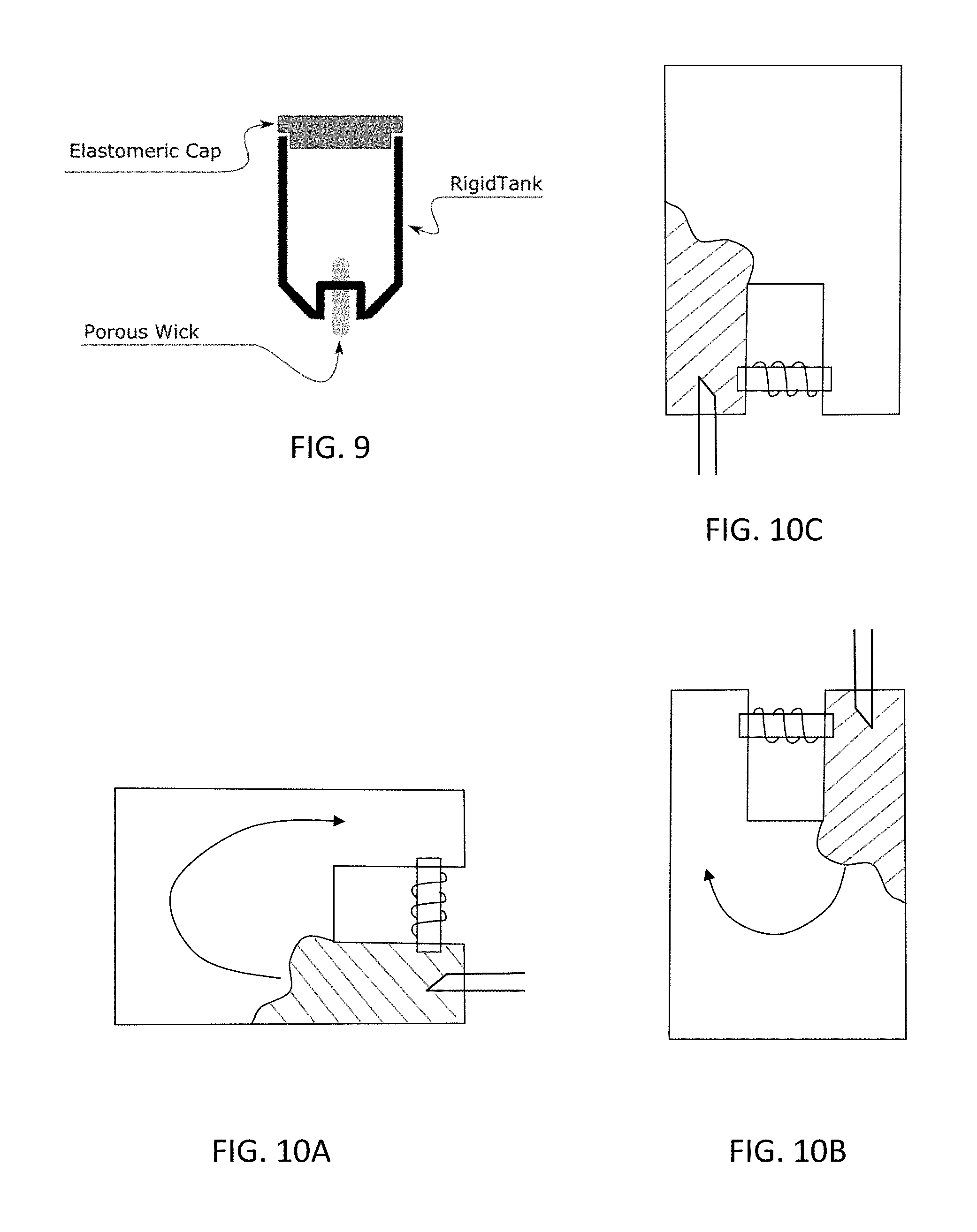
[0036] FIG. 9 is a front view of another variation of a cartridge, including a reservoir, for an electronic cigarette.
[0037] FIGS. 10A, 10B and 10C illustrate other variations of a method of filling a reservoir of a cartridge with a single needle. In these variations the liquid is filled from the same side as the wick, and the tank region (reservoir) is U-shaped. In general, one end of the wick may be confined to a smaller diameter region/smaller chamber so that it fills last, leaving the wick dry and able to vent air.
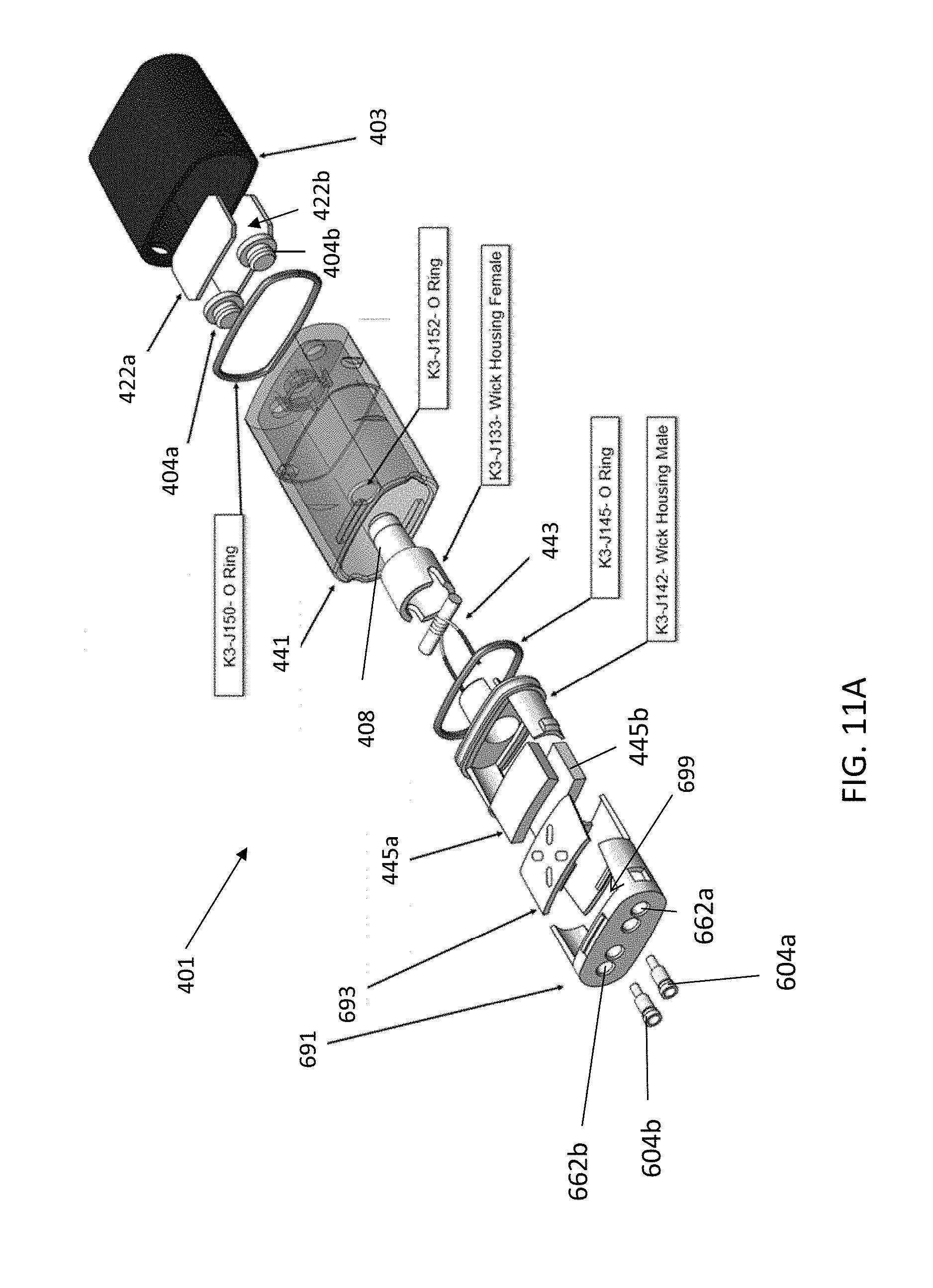
[0038] FIG. 11A illustrates an exploded view of a cartridge that may be filled as described herein.
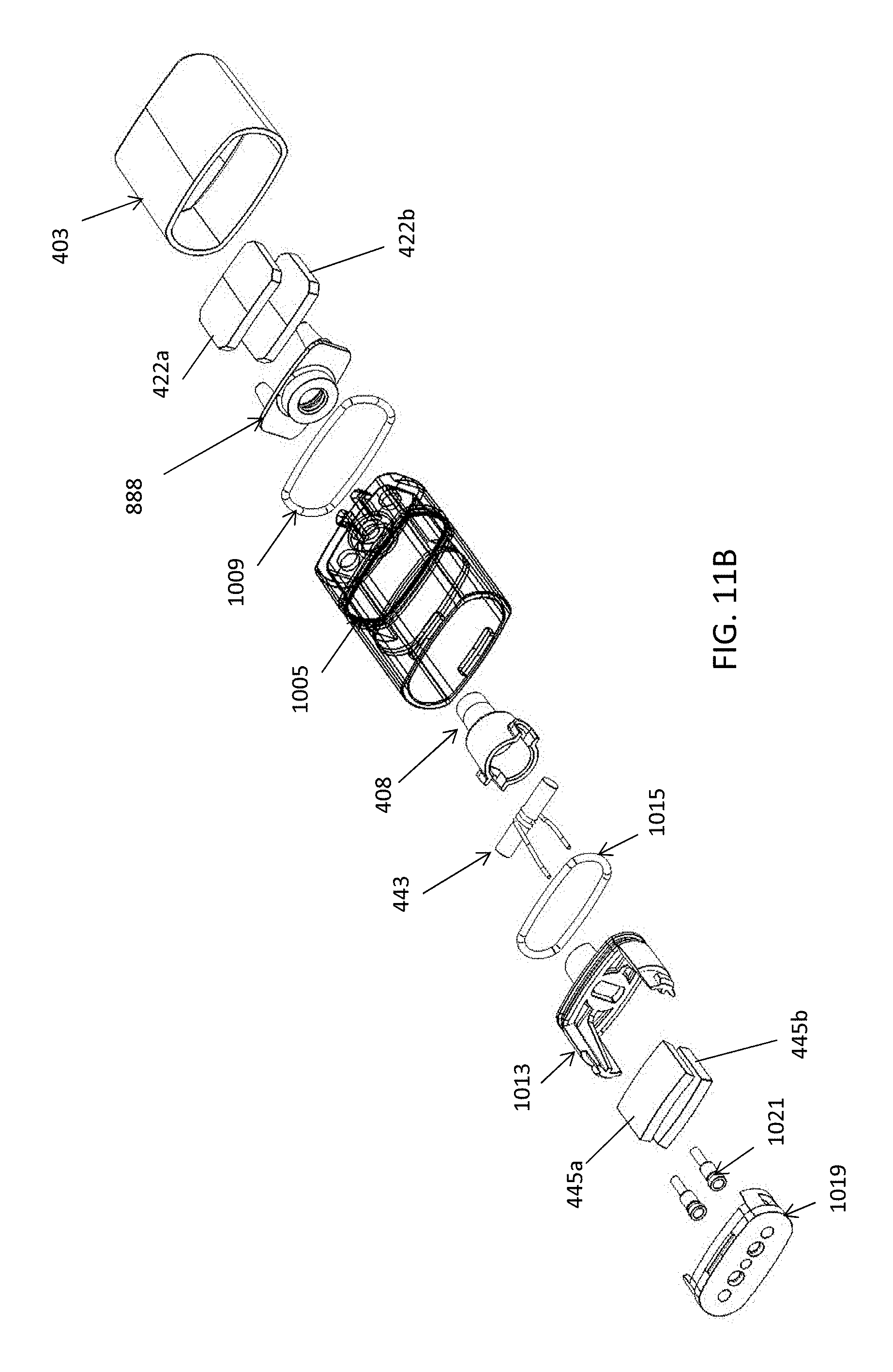
[0039] FIG. 11B is an alternative exploded view of a cartridge that may be filled as described herein.
DETAILED DESCRIPTION
[0040] Described herein are methods of filling a reservoir of an electronic cigarette or cartridge for an electronic cigarette so that air is not trapped within the cartridge. In particular, described herein are methods of filing a reservoir for an electronic cigarette including a porous wick extending out of the reservoir at a first end, without leakage, or overflow, until there is no air within the reservoir.
[0041] In any of the variations described herein, the reservoir being filled may be a cartridge which may be filled vaporizable material (e.g., an aqueous solution of tobacco or any other liquid solution). For example, FIG. 2 shows one example of a cartridge including a reservoir that may be filled as described herein. FIGS. 1A-1G show a schematic illustration of another example of cartridge. In general a cartridge may include a reservoir into which fluid may be filled, a tank 201 (housing the reservoir), an elastomeric cap, and a porous wick at one end of the tank, which passes from within the tank to an external surface. The porous wick may be any appropriate material, including woven, braided, fibrous, and knitted materials. The wick may be coupled with or integral with a heating element. For example, a wire for resistive heating may be wrapped around an external portion of the wick, forming a wick/coil assembly 205 as shown in FIG. 2. The wick may be any appropriate material, including metals, polymers, natural fibers, synthetic fibers, or combinations of these. The wick is porous and provides a capillary pathway for fluid within the tank through and into the wick; the capillary pathway is generally large enough to permit wicking of sufficient material to replace vaporized liquid transferred from the tank by capillary action (wicking) during use of the electronic cigarette, but may be small enough to prevent leakage of the vaporizable fluid material out of the cartridge during normal operation, including when applying pressure (e.g., squeezing) the cartridge. The external portion of the wick may include a wick housing 205. The wick housing and/or wick may be treated to prevent leakage. For example, the wick and/or wick housing may be coated after filling to prevent leakage and/or evaporation through the wick until activated by connecting to an electronic cigarette and/or applying current through the electrical contacts 207 (e.g., operation in an electronic cigarette), or otherwise using the cartridge. Any appropriate coating may be used, including a heat-vaporizable coating (e.g., a wax or other material), a frangible material, or the like.
[0042] The cartridge may also include an air path through the tank (shown as a tube 209 in FIG. 2), which may at least partially partition the volume of the tank. The tank may include an elastomeric potion, such as all or a portion of the side, bottom, top, etc. In FIG. 2, the tank is covered by an elastomeric cap 211 (elastomeric tank cap). The elastomeric portion (e.g., cap) may, in some variations, be on an opposite side from the wick.
[0043] In the variation shown in FIG. 2, the cartridge including the tank also include a cover (cap 215) and is configured to be used as a mouthpiece, so includes a mouthpiece portion 217 that is separated from the tank 201 by one or more absorbent pads 219.
[0044] In general, the methods described herein may include filling the tank (e.g. of a cartridge) that includes a wick at one end. The method may generally include positioning the empty and fully assembled tank (e.g. cartridge) so that it may be filled by a single needle that is inserted from the bottom or side (but not the top) of the empty tank. For example, the tank may be held on its side or upside down.
[0045] For example, FIGS. 3A-3F illustrate one example of filling as described herein, in which the tank is filled from a needle inserted into the bottom or lateral sides (where the lateral sides are not the top). In FIGS. 3A-3F, the filling system (e.g., needle, etc.) is inverted with respect to gravity so that the wick is not on the bottom. In FIG. 3A, the cartridge is ready to accept the dispensing needle through the elastomeric cap. During the first phase of fill liquid falls down around the needle that is injecting the liquid into the reservoir, immediately filling the reservoir in a way that the "additional vent" approach (shown in FIGS. 1A-1G) cannot. As filling progresses, air is displaced through the silica wick, at the top of the container in this example; the wick is dry, as shown in FIGS. 3B-3D. In FIG. 3B, the filling needle ("fill needle") pierces the elastomeric cap and begins dispensing. In this example a minimum safe distance for filling (e.g., the distance from the tip of the fill needle to the bottom of the opening of the needle opposite the tip) must be cleared by the needle before dispensing. In FIG. 3C the liquid fills the area between the needle opening and the elastomeric cap, and air is vented through the porous wick. By FIG. 3D, liquid being filled into the reservoir has reached one side of the wick, but venting may continue on the opposite side of the wick. In any of these examples the rate of filling maybe controlled. For example, the rate of filling may be controlled to be relatively steady/constant and avoid splashing (e.g., by ramping up to the filling rate when initially filling). In FIG. 3E, the liquid front has finally reached the second side of the wick, and the cartridge is completely full, and (in FIG. 3F) the needle may be retraced, as shown.
[0046] In some variations, which may be used with tank-style electronic cigarettes, the wick may be as close to the bottom of the container as possible to ensure that as much liquid as possible can be drawn out of the container; when the cartridge is inverted this results in the wick being the highest point in the container and therefore an ideal location to vent from.
[0047] The area that surrounds the wick outside the tank may be configured to accommodate some amount of excess liquid during normal use (e.g., the wick housing), which means that it is often palatable to allow some small amount of liquid to be forced through the wick during filling, since any overflow ends up in a manageable location. This allows the possibility to fill a cartridge completely with no geometrically defined bubble zones.
[0048] Finally, it may be acceptable to allow some small amount of overfill in this configuration without having to deal with any messes or excess liquid, which allows for the addition of a subtle feature in the filling process. In some variations, the pumping system measures the pressure that it is applying during fill, and that pressure can be used to detect when the liquid front has reached the wick. The dramatic reduction in cross sectional area when passing through the wick typically results in a large change in fluid resistance, which in turn results in a relatively large spike in pressure in the tank and fill system when the flow front reaches the wick. This signal can be detected and used to switch off the pump, which allows the system to fill cartridges of variable sizes with no captive air.
[0049] As mentioned, in some variation the filling is performed when the tank is on its side, rather than upside down. This is shown in FIGS. 4A-4H. This variation may be employed to achieve the same effect as the inverted method discussed above, and may be particularly useful when machinery constraints provide a challenge to orienting the system so that the needles points upwards with respect to gravity. This variation may also be particularly useful if the cartridge is not a simple empty container and has additional features that can influence the liquid flow front as it is inserted. In general, it is desired to cause the wick to be the last point to become wetted when filling to completely fill the tank; this may be done when the cartridge (tank) is lying down or even vertical. When there are obstructions in the tank or connected sub-regions of the tank formed by projections into the tank, filing from different angles (e.g., side filling) may take advantage of different levels of fluid restriction in different areas of the cartridge. In any of these variations, the filling may also take advantage of the large difference in viscosity between air and the liquid being filled. Such differences can also be exaggerated by filling at very high speeds (around 1 ml/sec in the case of a cartridge that is between about 12 mm.times.about 4 mm.times.22 mm). See FIGS. 4A-4H for details of how the flow front advances in a cartridge during this horizontal fill process to avoid captured air.
[0050] In FIG. 4A, the cartridge having an empty tank is fully assembled and positioned on its side, with the wick on a first side (perpendicular to the direction of gravity). In FIG. 4A, gravity is pointed in the direction of the page. Alternatively or additionally, the filling may be performed so quickly that viscous and inertial force dominate over the force of gravity. In FIG. 4B, the needle is inserted though the elastomeric cap opposite from the wick, and the filling may begin. The filling needle may be sharp and may include a beveled tip having the filling opening. The beveled opening may be oriented to direct the flow of filling liquid preferentially towards the bottom side of the cartridge (e.g., towards the page). In FIG. 4C, the flow front advances until it reaches the first wick end. The high rate of dispensing and fluid restricting of the wick may cause the flow front to advance within the cartridge instead of leaking out through the wick. In FIG. 4D, the internal tube restricts the flow of fluid from the side of the cartridge near the filling tube to the opposite side. In this example, fluid is restricted by the cannula (air path) to passing through the gap region between the walls of the tank and the cannula. This restriction may allow the filing to continue back towards the dispensing needle instead of starting to fill the opposite side from the needle (on the other side of the cannula). In FIG. 4E the proximity to the needle tip (dispensing head) may cause the flow front to finally cross the steel air path toward the end of the cartridge furthest from the wick (e.g., near the end from which the needle entered), eventually filling the furthest corner. In FIG. 4F, the flow front has advanced towards the wick as the top right (near the elastomeric cap) is filled, progressing towards the far side of the wick which is still venting. By FIG. 4G the flow front has reached the last free wick end at last, and after wetting it, no further air can escape (preventing it from venting captive air); by that point, filing is complete, as shown in FIG. 4H, and the hypodermic filling needle may be retracted, as shown.
[0051] This side-filling method may work well where there is some degree of fluid restriction (e.g., where, as here, a cannula or other obstruction is present in the tank). It also helps that fluid restriction through the wick is much higher when it is wetted than when it is dry, allowing it to behave effectively like a valve that creates a staged fill process. For example, filling the bottom, then the top. Similarly, the fluid restriction (governed in this case by the geometric arrangement or spacing) around the steel air path (cannula) is much higher than the fluid restriction back towards the needle, allowing the end far from the wick to fill in these examples, which, as shown in FIGS. 1A-1F is where air is trapped, forming a captive air zone in the 2 needle approach, even without gravity influencing that region to fill first as in the inverted filling technique show in FIGS. 3A-3H. Once the flow front reaches the far side of the air path it can simply fill towards the wick without risk of capturing any more air.
[0052] In cases in which the tank does not include an obstruction in the inner volume (e.g., where a feature similar to the steel air path in the cartridge shown in FIGS. 4A-4F is absent), a change to the needle geometry that causes the liquid to exit the needle in a direction normal to the axis of the needle (such as using a Witacre or Sprotte type needle, see FIGS. 6A-6B and 7A-B) may be used to influence the flow front to fill completely from the elastomer cap end to the wick end of the cartridge, as illustrated in FIGS. 8A-8F.
[0053] In this example, which is also a side-filling example, the cartridge including a tank is held sideways so that the wick is on one side and the needle is inserted from another side. The needle has a sharp distal tip and a more proximal side opening that directs the flow out of the needle perpendicular to the long axis of the needle. In FIG. 8A, a cartridge is viewed from above and ready for filling, otherwise fully assembled. In this example, gravity may be pointed down (towards the bottom of the page) or more preferable the cartridge is flat against a top surface and gravity is pointed into the page. Alternatively or additionally filling may be done rapidly so that viscous and inertial forces dominate over the gravitational forces. In FIG. 8B, the dispensing needle with side-exists (one or more preferably two side exits) is inserted into the tank reservoir and filing begins. The side exits (orifices) of the needle direct eh flow front to fill the area between the needle side exits and the elastomeric section. Filling then progresses from the right to left as shown in FIG. 8C. In FIG. 8D, the filling has further progressed and the dispensing needle may be adjusted to avoid air being captured between the wick housing and the needle (or between the needle and the wall of the tank. Preferably the needle is separated from the wall to entrap an air bubble.
[0054] In FIG. 8E, the flow front has reached both wick ends at approximately the same time, and filling is complete in FIG. 8F and the needle may be retracted. Any of the filling methods described herein may be performed in parallel with multiple needles and multiple assembled cartridges/tanks.
[0055] In all of these configurations we have depicted a style of tank with the wick reaching in to the tank in two locations. The risk of capturing air may be reduced if the wick reaches in to the tank in only one location, and the geometry of the tank may create a funnel towards that point, as would be the case with the variation shown in FIG. 9. All wick-venting filling methods and orientations described herein may work just as well or better with a cartridge of this format.
[0056] In general, the filling material (e.g., vaporizable material) that is injected into the tank may be any appropriate liquid. Examples of such liquid may include an aqueous solution of a nicotine salt (as incorporated by reference in its entirety above), or of a cannabis formulations. Any liquid solution may be used, including pharmaceutical solutions that may be vaporized for delivery (e.g., any liquid suitable for vaporization).
[0057] In some variations the cartridge may include a pre-pierced septum (e.g., elastomeric cap, etc.), and a blunt dispensing tip (filling needle) may be introduced through the existing septum flap to fill the tank reservoir. Alternatively or additionally any of these variations may include a resealable port of valve into which the needle is inserted for filling. This may reduce the required clearance of the needle (the minimum safe distance mentioned above). For example, a "star valve" may be formed (e.g., punched or laser cut, etc.) in a wall of the tank and/or the elastomeric top (septum), which may also allow liquid to be filled into the tank with a blunt dispensing tip. Alternatively or additionally, a mechanical fill port such as a poppet valve may be included in the cartridge and used for filling, rather than a penetrable septum like the elastomeric cap; this may also allow the use of a blunt dispensing tip, which may be designed to mate with the port.
[0058] As mentioned, any appropriate needle may be used, including those that direct the flow laterally (see e.g., FIGS. 6A-7B) or retrograde.
[0059] FIGS. 10A and 10B illustrate another variation of a filling method in which the needle is inserted from the same side as the wick. In this example, the filling may occur as described above, but may wrap around as shown in the arrow to fill the cartridge without leaving any air bubbles. In FIG. 10A, the cartridge is filled from the side (as described above) and may be lying flat (with a superior surface against a flat surface) so that gravity is into the page, or it may be inverted, as shown in FIG. 10B. Although it may be challenge. One or both of these filling arrangements. Note that a third variation is shown in FIG. 10C, where the liquid is filled from the bottom of the cartridge. In this case (as in FIGS. 10A-10B), liquid would preferentially flow into the tank vs. through the higher restriction of the wick, especially if filled slowly.
Alternative Cartridge Embodiments
[0060] The methods and apparatuses (including filling devices, systems, hardware and/or software for controlling filling) described herein may be used with any appropriate cartridge, including those shown in the exploded view of FIGS. 11A-11B.
[0061] For example, in FIG. 11A, the cartridge, whose components are described in greater detail below, may be filled by removing one or both plugs 404a, 404b, or by injection through these plugs, which may be formed of a self-healing material. In the exploded view of FIG. 11A the cartridge 401 includes a tank 441 configured to hold a liquid vaporizable material therein, a heater (e.g. a wick and coil assembly) 443 configured to heat the vaporizable material in the tank 441, and an air tube 408 extending from the tank to a mouthpiece 403. Contacts 535 are configured to connect with contacts 435 on the reusable component 411 to provide power to activate the wick and coil assembly 443. At the distal end of the cartridge the walls of the elongate and flattened tubular body 441 and a bottom cover piece 691 form an overflow leak chamber 699, which is shown with a pair of absorbent pads 495a,b are positioned along the long walls (along the diameter) of the overflow leak chamber. An option felt cover 693 may be included (also acting as an absorbent member). Parallel absorbent pads 422a,b can be positioned within the mouthpiece 403. The absorbent pads 422a,b are rectangular and parallel with one another. The absorbent pads 422a,b are positioned substantially parallel to the flat side of the device 400 (parallel with the plane of the length 1 and width w in FIG. 4A) and parallel with one another. In some embodiments, the pads 422a,b can be biased fully against the inside walls of the mouthpiece 403 so as to easily capture liquid that rolls along the walls (including during filling). A distance between the two pads 422a,b can be, for example, between 3 and 6 mm, such as between 4 and 5 mm, e.g., approximately 4.8 mm. The gap between the absorbent pads 422a,b advantageously prevents the pads from interfering with the air flow path when a user draws on the mouthpiece 403.
[0062] In general, over-flow pads, e.g., 445a,b may be positioned proximate to the tank 441, i.e., within an overflow leak chamber below the tank, to absorb liquid that may leak out of the tank 441 during filling and/or use. The over-flow pads 445a,b can be similarly placed parallel to one another and/or against the sides of the shell 431 as described above with respect to pads 422a,b.
[0063] Another example of a cartridge is shown in FIG. 11B. In this example, exemplary device 800 is similar to device 400 (similar reference numbers are therefore used) except that it includes a single plug 888 in the proximal section of the cartridge 801 (i.e., as opposed to the two tank seals 604a,b shown in FIG. 11A). The plug 888 is configured to simultaneously seal both outlets of the mouthpiece 403 while also sealing around the tube 408. As mentioned, filling may be performed as described herein, including injecting through the self-healing (e.g., a rubber or polymeric material).
[0064] In the exploded view of a cartridge shown in FIG. 11B, the apparatus includes a cartridge body 1005 that may be clear (transparent), opaque and/or translucent. The cartridge body may form a reservoir for the liquid vaporizable material, and particularly for a viscous liquid vaporizable material such as a cannabinoid oil, nicotine solution or other vaporizable material. The cartridge may include an outer seal (e.g., o-ring 1009) that seals the mouthpiece 403 over the body 1005. The reservoir (tank) may be sealed on the top (at the proximal end) under the mouthpiece by a single-piece plug 888 that covers multiple openings which may be used for filling the tank. The vaporization chamber may be formed at the bottom (distal end) of the cartridge; in exemplary cartridges described herein the vaporization chamber is formed from a cannula and housing piece 1011 that includes opening into which the wick (wick portion of wick and coil 443) passes into the chamber; the walls forming the vaporization chamber separate it from the tank and mate with a back piece 1013 that forms the bottom (distal end) of the tank within the cartridge body. This piece is also sealed (e.g., by an o-ring 1015) to the cartridge body from within the cartridge body, as shown. An air chamber is then formed between the bottom of the cartridge 1019 and the back piece 1013 of the tank. One or more (e.g., two) air openings 796, 796' through this bottom 1019 allow air to pass (after entering the cartridge receiver through one or more openings 894 in the side) into the distal end of the cartridge, into the air chamber region and then up through an opening into the vaporization chamber. The piece forming the bottom of the cartridge 1019 may also accommodate or include one or more (e.g., two) electrical connectors that are configured to mate with the connectors on the vaporizer base. As mentioned, these contacts may be wiper or scraping contacts. In FIG. 11B, they are shown as cans 1021, 1021' having openings into which the pins project to form an electrical contact.
[0065] Any of the methods (including user interfaces) described herein may be implemented as software, hardware or firmware, and may be described as a non-transitory computer-readable storage medium storing a set of instructions capable of being executed by a processor (e.g., computer, tablet, smartphone, etc.), that when executed by the processor causes the processor to control perform any of the steps, including but not limited to: displaying, communicating with the user, analyzing, modifying parameters (including timing, frequency, intensity, etc.), determining, alerting, or the like.
[0066] When a feature or element is herein referred to as being "on" another feature or element, it can be directly on the other feature or element or intervening features and/or elements may also be present. In contrast, when a feature or element is referred to as being "directly on" another feature or element, there are no intervening features or elements present. It will also be understood that, when a feature or element is referred to as being "connected", "attached" or "coupled" to another feature or element, it can be directly connected, attached or coupled to the other feature or element or intervening features or elements may be present. In contrast, when a feature or element is referred to as being "directly connected", "directly attached" or "directly coupled" to another feature or element, there are no intervening features or elements present. Although described or shown with respect to one embodiment, the features and elements so described or shown can apply to other embodiments. It will also be appreciated by those of skill in the art that references to a structure or feature that is disposed "adjacent" another feature may have portions that overlap or underlie the adjacent feature.
[0067] Terminology used herein is for the purpose of describing particular embodiments only and is not intended to be limiting of the invention. For example, as used herein, the singular forms "a", "an" and "the" are intended to include the plural forms as well, unless the context clearly indicates otherwise. It will be further understood that the terms "comprises" and/or "comprising," when used in this specification, specify the presence of stated features, steps, operations, elements, and/or components, but do not preclude the presence or addition of one or more other features, steps, operations, elements, components, and/or groups thereof. As used herein, the term "and/or" includes any and all combinations of one or more of the associated listed items and may be abbreviated as "/".
[0068] Spatially relative terms, such as "under", "below", "lower", "over", "upper" and the like, may be used herein for ease of description to describe one element or feature's relationship to another element(s) or feature(s) as illustrated in the figures. It will be understood that the spatially relative terms are intended to encompass different orientations of the device in use or operation in addition to the orientation depicted in the figures. For example, if a device in the figures is inverted, elements described as "under" or "beneath" other elements or features would then be oriented "over" the other elements or features. Thus, the exemplary term "under" can encompass both an orientation of over and under. The device may be otherwise oriented (rotated 90 degrees or at other orientations) and the spatially relative descriptors used herein interpreted accordingly. Similarly, the terms "upwardly", "downwardly", "vertical", "horizontal" and the like are used herein for the purpose of explanation only unless specifically indicated otherwise.
[0069] Although the terms "first" and "second" may be used herein to describe various features/elements (including steps), these features/elements should not be limited by these terms, unless the context indicates otherwise. These terms may be used to distinguish one feature/element from another feature/element. Thus, a first feature/element discussed below could be termed a second feature/element, and similarly, a second feature/element discussed below could be termed a first feature/element without departing from the teachings of the present invention.
[0070] Throughout this specification and the claims which follow, unless the context requires otherwise, the word "comprise", and variations such as "comprises" and "comprising" means various components can be co-jointly employed in the methods and articles (e.g., compositions and apparatuses including device and methods). For example, the term "comprising" will be understood to imply the inclusion of any stated elements or steps but not the exclusion of any other elements or steps.
[0071] In general, any of the apparatuses and methods described herein should be understood to be inclusive, but all or a sub-set of the components and/or steps may alternatively be exclusive, and may be expressed as "consisting of" or alternatively "consisting essentially of" the various components, steps, sub-components or sub-steps.
[0072] As used herein in the specification and claims, including as used in the examples and unless otherwise expressly specified, all numbers may be read as if prefaced by the word "about" or "approximately," even if the term does not expressly appear. The phrase "about" or "approximately" may be used when describing magnitude and/or position to indicate that the value and/or position described is within a reasonable expected range of values and/or positions. For example, a numeric value may have a value that is +/-0.1% of the stated value (or range of values), +/-1% of the stated value (or range of values), +/-2% of the stated value (or range of values), +/-5% of the stated value (or range of values), +/-10% of the stated value (or range of values), etc. Any numerical values given herein should also be understood to include about or approximately that value, unless the context indicates otherwise. For example, if the value "10" is disclosed, then "about 10" is also disclosed. Any numerical range recited herein is intended to include all sub-ranges subsumed therein. It is also understood that when a value is disclosed that "less than or equal to" the value, "greater than or equal to the value" and possible ranges between values are also disclosed, as appropriately understood by the skilled artisan. For example, if the value "X" is disclosed the "less than or equal to X" as well as "greater than or equal to X" (e.g., where X is a numerical value) is also disclosed. It is also understood that the throughout the application, data is provided in a number of different formats, and that this data, represents endpoints and starting points, and ranges for any combination of the data points. For example, if a particular data point "10" and a particular data point "15" are disclosed, it is understood that greater than, greater than or equal to, less than, less than or equal to, and equal to 10 and 15 are considered disclosed as well as between 10 and 15. It is also understood that each unit between two particular units are also disclosed. For example, if 10 and 15 are disclosed, then 11, 12, 13, and 14 are also disclosed.
[0073] Although various illustrative embodiments are described above, any of a number of changes may be made to various embodiments without departing from the scope of the invention as described by the claims. For example, the order in which various described method steps are performed may often be changed in alternative embodiments, and in other alternative embodiments one or more method steps may be skipped altogether. Optional features of various device and system embodiments may be included in some embodiments and not in others. Therefore, the foregoing description is provided primarily for exemplary purposes and should not be interpreted to limit the scope of the invention as it is set forth in the claims.
[0074] The examples and illustrations included herein show, by way of illustration and not of limitation, specific embodiments in which the subject matter may be practiced. As mentioned, other embodiments may be utilized and derived there from, such that structural and logical substitutions and changes may be made without departing from the scope of this disclosure. Such embodiments of the inventive subject matter may be referred to herein individually or collectively by the term "invention" merely for convenience and without intending to voluntarily limit the scope of this application to any single invention or inventive concept, if more than one is, in fact, disclosed. Thus, although specific embodiments have been illustrated and described herein, any arrangement calculated to achieve the same purpose may be substituted for the specific embodiments shown. This disclosure is intended to cover any and all adaptations or variations of various embodiments. Combinations of the above embodiments, and other embodiments not specifically described herein, will be apparent to those of skill in the art upon reviewing the above description.
* * * * *
D00000
D00001
D00002
D00003
D00004
D00005
D00006
D00007
D00008
D00009
XML
uspto.report is an independent third-party trademark research tool that is not affiliated, endorsed, or sponsored by the United States Patent and Trademark Office (USPTO) or any other governmental organization. The information provided by uspto.report is based on publicly available data at the time of writing and is intended for informational purposes only.
While we strive to provide accurate and up-to-date information, we do not guarantee the accuracy, completeness, reliability, or suitability of the information displayed on this site. The use of this site is at your own risk. Any reliance you place on such information is therefore strictly at your own risk.
All official trademark data, including owner information, should be verified by visiting the official USPTO website at www.uspto.gov. This site is not intended to replace professional legal advice and should not be used as a substitute for consulting with a legal professional who is knowledgeable about trademark law.