Thrust Reversal On Aircraft Fuselage With A Wing Profile
LANG; Dieter
U.S. patent application number 16/184218 was filed with the patent office on 2019-08-22 for thrust reversal on aircraft fuselage with a wing profile. The applicant listed for this patent is Dieter LANG. Invention is credited to Dieter LANG.
| Application Number | 20190256192 16/184218 |
| Document ID | / |
| Family ID | 67481871 |
| Filed Date | 2019-08-22 |


| United States Patent Application | 20190256192 |
| Kind Code | A1 |
| LANG; Dieter | August 22, 2019 |
THRUST REVERSAL ON AIRCRAFT FUSELAGE WITH A WING PROFILE
Abstract
An aircraft includes a fuselage having a wing profile. An apparatus for thrust reversal is disposed on the tail of the aircraft. Air feed takes place from the outside, by way of a braking flap with an air intake channel and/or from a propelling machine.
| Inventors: | LANG; Dieter; (Mohlsdorf-Teichwolframsdorf, DE) | ||||||||||
| Applicant: |
|
||||||||||
|---|---|---|---|---|---|---|---|---|---|---|---|
| Family ID: | 67481871 | ||||||||||
| Appl. No.: | 16/184218 | ||||||||||
| Filed: | November 8, 2018 |
| Current U.S. Class: | 1/1 |
| Current CPC Class: | B64C 1/0009 20130101; B64D 27/14 20130101; B64C 2001/0045 20130101; B64C 2003/143 20130101; B64C 3/141 20130101; B64C 39/10 20130101; B64C 9/326 20130101; B64C 30/00 20130101 |
| International Class: | B64C 9/32 20060101 B64C009/32; B64D 27/14 20060101 B64D027/14; B64C 1/00 20060101 B64C001/00; B64C 30/00 20060101 B64C030/00 |
Foreign Application Data
| Date | Code | Application Number |
|---|---|---|
| Feb 16, 2018 | DE | 10 2018 001 247.7 |
Claims
1. An aircraft comprising: (a) a fuselage having a nose and a wing profile; (b) a propelling machine in the fuselage for propelling the aircraft up to hypersonic speed; (c) a tail connected to the fuselage, the tail comprising a plurality of tail deflection flaps movable between an open position and a closed position; (d) a first air supply channel disposed in the fuselage, wherein the first air supply channel is connected and supplies air to the propelling machine, the first air supply channel having an air inlet opening; (e) a second air supply channel disposed in the fuselage, wherein the second air supply channel is connected and supplies air to the tail; (f) a braking flap connected to the second air supply channel, wherein the braking flap is movable between an open position and a closed position; (g) a plurality of nose deflection flaps on the nose, wherein the nose deflection flaps are movable between an open position and a closed position; and (h) an exhaust gas channel disposed in the fuselage, wherein the exhaust gas channel is connected to the propelling machine and extends toward the nose; wherein opening the braking flap and the tail deflection flaps causes a thrust reversal on the tail.
2. The aircraft according to claim 1, further comprising a further exhaust channel disposed in the fuselage, wherein the further exhaust channel is connected to the propelling machine and extends toward the tail deflection flaps.
3. The aircraft according to claim 1, wherein the propelling machine comprises a gas turbine.
Description
CROSS REFERENCE TO RELATED APPLICATIONS
[0001] Applicant claims priority under 35 U.S.C. 119 of German Application No. 10 2018 001 247.7 filed on Feb. 16, 2018, the disclosure of which is herein incorporated by reference.
BACKGROUND OF THE INVENTION
1. Field of the Invention
[0002] The invention relates to aircraft which travel at speeds of up to supersonic speeds and which include a braking and landing system.
2. The Prior Art
[0003] German Patent Application No. 10 2013 020 778.9 describes an apparatus for vertical take-off of a vehicle.
[0004] German Patent Application No. 10 2014 015 662.1 shows a vehicle for traveling at supersonic speeds with structure configured to provide the possibility of thrust and counter-thrust. There can be problems in connection with braking and landing of these vehicles.
SUMMARY OF THE INVENTION
[0005] A goal of the invention is to give an aircraft an additional braking and landing system.
[0006] An aircraft according to the invention includes a fuselage, a propelling machine in the fuselage, a tail, a first air supply channel, a second air supply channel, a braking flap, a plurality of nose deflection flaps, and an exhaust gas channel. The fuselage has a nose and a wing profile. The propelling machine is for propelling the aircraft up to hypersonic speed. The tail is connected to the fuselage and includes a plurality of tail deflection flaps movable between an open position and a closed position. The first air supply channel is disposed in the fuselage and is connected and supplies air to the propelling machine. The first air supply channel has an air inlet opening. The second air supply channel is disposed in the fuselage. The second air supply channel is connected and supplies air to the tail. The braking flap is connected to the second air supply channel. The braking flap is movable between an open position and a closed position. The nose deflection flaps are movable between an open position and a closed position. The exhaust gas channel is disposed in the fuselage, is connected to the propelling machine, and extends toward the nose. Opening the braking flap and the tail deflection flaps causes a thrust reversal on the tail.
[0007] In another embodiment, the aircraft also includes a further exhaust channel disposed in the fuselage. The further exhaust channel is connected to the propelling machine and extends toward the tail deflection flaps.
[0008] In another embodiment, the propelling machine of the aircraft includes a gas turbine.
BRIEF DESCRIPTION OF THE DRAWINGS
[0009] Other objects and features of the present improvements will become apparent from the following detailed description and the related accompanying drawings. However, these accompanying drawings are designed for the purpose of illustration only, rather than limiting the present utility model.
[0010] In these accompanying drawings, similar reference characters denote similar elements throughout the views.
[0011] FIG. 1 is a side view of a first embodiment of an aircraft according to the invention; and
[0012] FIG. 2 is a side view of another embodiment of an aircraft according to the invention.
DETAILED DESCRIPTION OF THE INVENTION
[0013] The present invention will be further described below in detail by embodiments with reference to the accompanying drawings, and the protection scope of the present invention is not limited thereto.
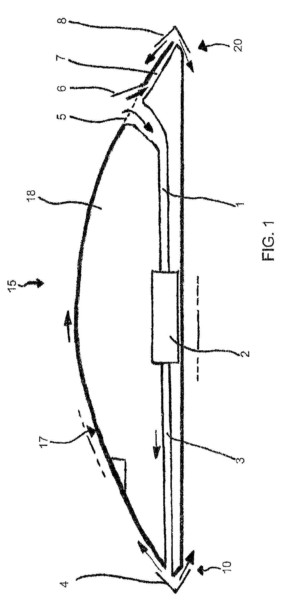
[0014] The aircraft 15 shown in FIG. 1 includes a fuselage 18, a propelling machine 2 in the fuselage 18, a tail 20, a first air supply channel 1, a second air supply channel 7, a braking flap 6, a plurality of nose deflection flaps 4, and an exhaust gas channel 3. The fuselage 18 has a nose 10 and a wing profile 17. The propelling machine 2 is for propelling the aircraft 15 up to hypersonic speed. The tail 20 is connected to the fuselage 18 and includes a plurality of tail deflection flaps 8 movable between an open position and a closed position. The first air supply channel 1 is disposed in the fuselage 18 and is connected and supplies air to the propelling machine 2. The first air supply channel 1 has an air inlet opening 5. The second air supply channel 7 is disposed in the fuselage 18. The second air supply channel 7 is connected and supplies air to the tail 20. The braking flap 6 is connected to the second air supply channel 7. The braking flap 6 is movable between an open position and a closed position, with the braking flap 6 being shown in the open position in FIG. 1. The nose deflection flaps 4 are movable between an open position and a closed position. The exhaust gas channel 3 is disposed in the fuselage 18, is connected to the propelling machine 2, and extends toward the nose 10. Opening the braking flap 6 and the tail deflection flaps 8 causes a thrust reversal on the tail 20.
[0015] In the aircraft shown in FIG. 1, the propelling machine 2 of the aircraft 15 is a gas turbine.
[0016] Take-off takes place by way of the gas turbine sucking in air via a first air supply channel 1 and the air intake opening 5. The gas turbine produces pressurized air, and that pressurized air is guided to the nose 10 via the exhaust gas channel 3. The escaping pressurized air escapes at the nose 10 and is led over the wing profile 17 and under the wing profile 17 of the fuselage 18. The escaping air moves with high velocity from 0 up to around 1000 km/h as needed. The deflection flap 4 is open for the take-off, and the braking flap 6 and the deflection flap 8 at the tail 20 are closed for the take-off. The landing follows in reversed manner via counter-thrust and exiting of the reduced compressed air at the nose 10.
[0017] Braking and landing of the aircraft takes place via opening the braking flap 6 and opening the deflection flap 8. Thrust reversal takes place.
[0018] Lift is ensured via the fuselage 18 having a wing profile 17.
[0019] In the further embodiment shown in FIG. 2, the structure and function of the aircraft 15' are similar to those of the aircraft 15 shown in FIG. 1. The aircraft 15' shown in FIG. 2 also includes, however, a further exhaust gas channel 9. The further exhaust gas channel 9 is connected to the propelling machine 2 and extends toward the tail deflection flaps 8.
REFERENCE SYMBOL LIST
[0020] 1 first air supply channel [0021] 2 gas turbine [0022] 3 exhaust gas channel [0023] 4 deflection flap on nose [0024] 5 air intake opening [0025] 6 braking flap [0026] 7 second air supply channel to tail [0027] 8 deflection flap on tail [0028] 9 further exhaust gas channel [0029] 10 nose [0030] 15, 15' aircraft [0031] 17 wing profile [0032] 18 fuselage [0033] 20 tail
* * * * *
D00000
D00001
D00002
XML
uspto.report is an independent third-party trademark research tool that is not affiliated, endorsed, or sponsored by the United States Patent and Trademark Office (USPTO) or any other governmental organization. The information provided by uspto.report is based on publicly available data at the time of writing and is intended for informational purposes only.
While we strive to provide accurate and up-to-date information, we do not guarantee the accuracy, completeness, reliability, or suitability of the information displayed on this site. The use of this site is at your own risk. Any reliance you place on such information is therefore strictly at your own risk.
All official trademark data, including owner information, should be verified by visiting the official USPTO website at www.uspto.gov. This site is not intended to replace professional legal advice and should not be used as a substitute for consulting with a legal professional who is knowledgeable about trademark law.