System For Delivering Anchors For Treating Incontinence
Lamson; Theodore C. ; et al.
U.S. patent application number 16/401783 was filed with the patent office on 2019-08-22 for system for delivering anchors for treating incontinence. The applicant listed for this patent is NeoTract, Inc.. Invention is credited to Joseph Catanese, III, Floria Cheng, Michael Gearhart, Theodore C. Lamson, Matthew McLean, James W. Niederjohn, Brian Y. Tachibana.
| Application Number | 20190254799 16/401783 |
| Document ID | / |
| Family ID | 49513066 |
| Filed Date | 2019-08-22 |


View All Diagrams
| United States Patent Application | 20190254799 |
| Kind Code | A1 |
| Lamson; Theodore C. ; et al. | August 22, 2019 |
SYSTEM FOR DELIVERING ANCHORS FOR TREATING INCONTINENCE
Abstract
A system and associated method for manipulating tissues and anatomical or other structures in medical applications for the purpose of treating incontinence. In one aspect, the system includes a delivery device configured to deploy and implant anchor devices for distracting and/or retracting the urethra or tissues proximate thereto, or to maintain a position of a urethra in response to intra-abdominal pressures.
| Inventors: | Lamson; Theodore C.; (Pleasanton, CA) ; Catanese, III; Joseph; (San Leandro, CA) ; McLean; Matthew; (San Francisco, CA) ; Niederjohn; James W.; (San Jose, CA) ; Cheng; Floria; (San Francisco, CA) ; Tachibana; Brian Y.; (Oakland, CA) ; Gearhart; Michael; (Fremont, CA) | ||||||||||
| Applicant: |
|
||||||||||
|---|---|---|---|---|---|---|---|---|---|---|---|
| Family ID: | 49513066 | ||||||||||
| Appl. No.: | 16/401783 | ||||||||||
| Filed: | May 2, 2019 |
Related U.S. Patent Documents
| Application Number | Filing Date | Patent Number | ||
|---|---|---|---|---|
| 13852756 | Mar 28, 2013 | 10292801 | ||
| 16401783 | ||||
| 61617244 | Mar 29, 2012 | |||
| Current U.S. Class: | 1/1 |
| Current CPC Class: | A61B 2017/00893 20130101; A61B 17/0401 20130101; A61B 2017/0409 20130101; A61B 2017/00805 20130101; A61B 2017/00274 20130101; A61F 2/0022 20130101; A61B 17/0218 20130101; A61F 2/0036 20130101; A61B 2017/0419 20130101; A61B 2017/06052 20130101 |
| International Class: | A61F 2/00 20060101 A61F002/00; A61B 17/04 20060101 A61B017/04 |
Claims
1. A method for treating incontinence, comprising: passing a first anchor through anterior periurethral fascia and implanting the first anchor, wherein the first anchor is connected to a tensioning connector; applying tension to the tensioning connector; and implanting a second anchor and connecting the second anchor to the tensioning connector, wherein the tension along the tensioning connector lifts a portion of a urethra towards a portion of the abdomen thereby reducing incontinence.
2. The method of claim 1, wherein the tensioning connector does not pass through a urethral lumen when the tensioning connector is in position to lift the portion of the urethra towards the portion of the abdomen.
3. The method of claim 1, wherein the first anchor is implanted in lateral tissue.
4. The method of claim 1, wherein the first anchor is implanted in bone.
5. The method of claim 1, wherein the second anchor is implanted in lateral tissue.
6. The method of claim 1, wherein the second anchor is implanted in bone.
7. The method of claim 1, wherein the first anchor comprises a tubular body portion and a tail portion.
8. The method of claim 1, wherein the second anchor comprises a slotted portion.
9. A method for treating incontinence, comprising: passing a first anchor through anterior periurethral fascia and implanting the first anchor, wherein the first anchor is connected to a first tensioning connector; passing a second anchor into a portion of the urethral lumen and connecting the second anchor to the first tensioning connector; passing a third anchor through anterior periurethral fascia and implanting the third anchor, wherein the third anchor is connected to a second tensioning connector; applying tension to the second tensioning connector; and implanting a fourth anchor in an area proximate the first anchor or the first tensioning connector and connecting the fourth anchor to the second tensioning connector, wherein the tension along the second tensioning connector lifts a portion of a urethra towards a portion of the abdomen thereby reducing incontinence.
10. The method of claim 9 further comprising passing a fifth anchor through anterior periurethral fascia and implanting the fifth anchor, wherein the fifth anchor is connected to a third tensioning connector; applying tension to the third tensioning connector; and implanting a sixth anchor in an area proximate the first anchor or the first tensioning connector and connecting the sixth anchor to the third tensioning connector, wherein the tension along the third tensioning connector lifts a portion of a urethra towards a portion of the abdomen thereby reducing incontinence.
11. The method of claim 9, wherein the third anchor is implanted in lateral tissue.
12. The method of claim 9, wherein the third anchor is implanted in bone.
13. The method of claim 10, wherein the fifth anchor is implanted in lateral tissue.
14. The method of claim 10, wherein the fifth anchor is implanted in bone.
15. The method of claim 9, wherein the first and third anchors comprise a tubular body portion and a tail portion.
16. The method of claim 9, wherein the second and fourth anchors comprise a slotted portion.
17. The method of claim 10, wherein the fifth anchor comprises a tubular body portion and a tail portion.
18. The method of claim 10, wherein the sixth anchor comprises a slotted portion.
Description
CROSS-REFERENCE TO RELATED APPLICATIONS
[0001] This application is a continuation of U.S. patent application Ser. No. 13/852,756, filed Mar. 28, 2013, entitled "System for Delivering Anchors for Treating Incontinence," which claims priority to and the benefit of U.S. Provisional Application No. 61/617,244 filed Mar. 29, 2012, entitled "System for Delivering Anchors for Treating Incontinence," each of which is incorporated herein by reference in its entirety.
FIELD OF THE INVENTION
[0002] The present invention relates generally to medical devices and methods, and more particularly to systems and associated methods for manipulating or retracting tissues and anatomical or other structures within the body of human or animal subjects for the purpose of treating incontinence. Urinary incontinence is any involuntary leakage of urine. It almost always results from an underlying treatable medical condition.
[0003] Normal continence involves a balance between urethral closure and detrusor muscle activity. The body stores urine in the urinary bladder. The bladder connects to the urethra, the tube through which urine leaves the body. Urethral pressure normally exceeds bladder pressure, resulting in urine remaining in the bladder. When sphincter muscles surrounding the urethra relax, urine is passed out of the body. Incontinence will occur if the bladder muscles suddenly contract or muscles surrounding the urethra suddenly relax.
[0004] There are a number of causes of incontinence. An enlarged prostate may be cause of incontinence, particularly urge incontinence, in men after the age of 40. Sometimes prostate cancer may also be associated with urinary incontinence. While urinary incontinence affects older men more often than younger men, the onset of incontinence can happen at any age. Recent estimates by the National Institutes of Health (NIH) suggest that 17 percent of men over age 60, an estimated 600,000 men, experience urinary incontinence, with this percentage increasing with age. Incontinence is treatable and often curable at all ages. Incontinence in men usually occurs because of problems with muscles that help to hold or release urine.
[0005] Incontinence in women can result from physical changes from pregnancy and childbirth. Menopause can also contribute to stress incontinence. Incontinence can worsen during the week before the menstrual period. At that time, lowered estrogen levels may lead to lower muscular pressure around the urethra, increasing chances of leakage. The incidence of incontinence increases following menopause, similarly because of lowered estrogen levels. As much as 35% of the total population over the age of 60 years is estimated to be incontinent, with women twice as likely as men to experience incontinence. One in three women over the age of 60 years are estimated to have bladder control problems. Incontinence is expensive to the health care system and nursing home industry as more than 50% of nursing facility admissions are related to incontinence. Further, disorders like multiple sclerosis, spina bifida, Parkinson's disease, strokes and spinal cord injury can all interfere with nerve function of the bladder.
[0006] There are also a number of different types of incontinence. Stress incontinence, also known as effort incontinence, is due essentially to insufficient strength of the pelvic floor muscles. Urge incontinence is generally due to involuntary loss of urine occurring for no apparent reason while suddenly feeling the need or urge to urinate. Overflow incontinence refers to people finding that they cannot stop their bladders from constantly dribbling or continuing to dribble for some time after they have passed urine.
[0007] Incontinence treatment options include behavior management, medications and surgery. Some approaches address the problem symptomatically, and can be applicable to more than one type of incontinence. Absorbent pads and various types of urinary catheters may be employed to help certain individuals. Men also can use an external urine collection device that is worn around the penis. These are traditionally referred to as condom catheters. Absorbent products include shields, undergarments, protective underwear, briefs, diapers, adult diapers and underpads.
[0008] Benign Prostatic Hyperplasia (BPH) is one of the most common medical conditions that affect men, especially elderly men. It has been reported that, in the United States, more than half of all men have histopathologic evidence of BPH by age 60 and, by age 85, approximately 9 out of 10 men suffer from the condition. Moreover, the incidence and prevalence of BPH are expected to increase as the average age of the population in developed countries increases. Although BPH is rarely life threatening, it can lead to numerous clinical conditions including urinary retention, renal insufficiency, recurrent urinary tract infection, incontinence, hematuria, and bladder stones.
[0009] The prostate gland enlarges throughout a man's life. In some men, the prostatic capsule around the prostate gland may prevent the prostate gland from enlarging further. This causes the inner region of the prostate gland to squeeze the urethra. This pressure on the urethra increases resistance to urine flow through the region of the urethra enclosed by the prostate. Thus the urinary bladder has to exert more pressure to force urine through the increased resistance of the urethra. Chronic over-exertion causes the muscular walls of the urinary bladder to remodel and become stiffer. This combination of increased urethral resistance to urine flow and stiffness and hypertrophy of urinary bladder walls leads to a variety of lower urinary tract symptoms (LUTS) that may severely reduce the patient's quality of life. These symptoms include weak or intermittent urine flow while urinating, straining when urinating, hesitation before urine flow starts, feeling that the bladder has not emptied completely even after urination, dribbling at the end of urination or leakage afterward, increased frequency of urination particularly at night, urgent need to urinate etc.
[0010] In addition to patients with BPH, LUTS may also be present in patients with prostate cancer, prostate infections, and chronic use of certain medications (e.g. ephedrine, pseudoephedrine, phenylpropanolamine, antihistamines such as diphenhydramine, chlorpheniramine etc.) that cause urinary retention especially in men with prostate enlargement.
[0011] Surgical procedures for treating BPH symptoms include Transurethal Resection of Prostate (TURP), Transurethral Electrovaporization of Prostate (TVP), Transurethral Incision of the Prostate (TUIP), Laser Prostatectomy and Open Prostatectomy. Minimally invasive procedures for treating BPH symptoms include Transurethral Microwave Thermotherapy (TUMT), Transurethral Needle Ablation (TUNA), Interstitial Laser Coagulation (ILC), and Prostatic Stents.
[0012] There have been advances in developing minimally invasive devices and methods for lifting, stabilizing and repositioning of tissues. There remains, however, a need for the development of new devices and methods that can be used for various procedures where it is desired to lift, compress, support, stabilize, modify or reposition tissues to treat incontinence. In particular, there is a need for alternative apparatus and treatment approaches for the purpose of manipulating the urethra and tissues surrounding the urethra. Various structures ensuring an effective interventional procedure have been found to be needed.
[0013] The present disclosure addresses these and other needs.
SUMMARY
[0014] Briefly and in general terms, the present invention is directed towards an apparatus and method for deploying an anchor assembly within a patient's body to accomplish treating incontinence. A delivery device is provided to access the anatomy targeted for the interventional procedure, such as a urethra. The delivery device facilitates the implantation of the anchor assembly in a manner accomplishing retraction or displacement of tissue. The delivery device is configured to accomplish the assembly of the anchor assembly in situ and can also automatically determine a length of the anchor assembly.
[0015] In one approach, one or more anchor assemblies are configured to reposition, stabilize or reduce the mobility of a portion of a urethra upwardly with respect to surrounding tissue. The anchor also can be configured to reduce a lumen size of the urethra. A proximal portion of the anchor assembly can be placed within anterior or lateral sections of the urethra. The anchor assemblies can also be positioned laterally relative to the urethra and implanted to maintain a constant position of the urethra against increases in intra-abdominal pressure. Moreover, one or more anchor assemblies can be configured about the prostate to lift or maintain a position of a portion of a urethra in a male patient. In a female patient, a portion of an anchor assembly can be passed through anterior periurethral fascia to the exclusion of or including the urethral lumen, and anchored to surrounding tissue to thereby reposition, stabilize or maintain positioning of a urethra, or reduce or modify the size of the urethra.
[0016] The delivery apparatus of the present disclosure includes various subassemblies, which are mobilized via an actuator or other manually accessible structure. The apparatus is sized and shaped so that it can be placed transurethrally or it can be configured to be inserted through a surgical incision so that access to tissue surrounding a urethra can be accessed. The operation of the subassemblies is coordinated and synchronized to ensure accurate and precise implantation of an anchor assembly. In one embodiment, the delivery device is embodied in a tissue retraction assembly.
[0017] In one particular aspect, the present invention is directed towards a delivery device, which accomplishes the delivery of a first or distal anchor assembly component at a first location within a patient's body and the delivery of a second or proximal anchor assembly component at a second location within the patient. The device also accomplishes imparting tension during delivery to a connector to hold it while attaching the proximal anchor in situ. The procedure can be viewed employing a scope inserted in the device. Also, the delivery device can be sized and shaped to be compatible inside a sheath up to 24 F, preferably a 19 F sheath or smaller.
[0018] The anchor assembly can be configured to accomplish approximating, retracting, lifting, compressing, supporting, stabilizing, or repositioning tissue within the body of a human or animal subject. Moreover, the apparatus configured to deploy the anchor assembly as well as the anchor assembly itself are configured to complement and cooperate with body anatomy. Further, the anchor assembly can be coated or imbedded with therapeutic or diagnostic substances, in particular Botulinum toxin, or a silver ion coating or such substances can be introduced into or near an interventional site by the anchor deployment device or other structure.
[0019] In various approaches, the anchor can include a distal anchor connected to a proximal anchor by a connector. The distal anchor has a body with a tail. The proximal anchor can include a pair of spaced members, which are configured to capture and deform the connector there between and prevent the connector from disengaging from the anchor device once engaged. The mechanism of connector attachment and strength of the assembly is a combination of compression of the connector between deformable structure of the anchor as well as disruption of the connector surface by the anchor. The deformable structure provides surface contact and focuses the compressive forces that cause the connector to conform about the anchor.
[0020] The anchor assembly can also be characterized by a connector embodying multiple strands. Such strands can be spaced upon delivery of the anchor assembly to provide a larger supporting structure. The anchor assembly can further define a sling structure including a woven connector connecting spaced anchor members.
[0021] Various alternative methods of use are contemplated. Thus, a transurethral approach to anchor assembly delivery as well as an approach through a surgical incision are contemplated. The disclosed apparatus can be used to alter flow of a body fluid through a body lumen, such as for the purpose of treating urinary incontinence. Also, the disclosure has a myriad of other potential surgical, therapeutic, cosmetic or reconstructive applications, such as where a tissue, organ, graft or other material requires stabilizing, retracting, lifting, repositioning, compression, modifying or support.
[0022] In a specific application, the disclosed apparatus are contemplated to be employed to reposition, stabilize or maintain positioning of a portion of a urethra or can be used to alter or reduce the size of the urethra. In one aspect, an anchoring device housed within a delivery device is inserted into a urethra transurethrally and the delivery device is employed to reconfigure the urethra.
[0023] Other features and advantages of the present invention will become apparent from the following detailed description, taken in conjunction with the accompanying drawings, which illustrate, by way of example, the principles of the invention.
BRIEF DESCRIPTION OF THE DRAWINGS
[0024] FIG. 1 is a cross-sectional view, depicting anatomy surrounding a urethra in a human male subject;
[0025] FIG. 2 is an enlarged cross-sectional view, depicting anatomy surrounding a prostate;
[0026] FIG. 3 is a cross-sectional view, depicting anatomy surrounding a urethra in a female subject;
[0027] FIG. 4 is a perspective side view, depicting one embodiment of an anchor assembly;
[0028] FIGS. 5A-D are side and perspective views, depicting one embodiment of a delivery device and various features thereof;
[0029] FIG. 5A is a view of a first embodiment of a delivery device;
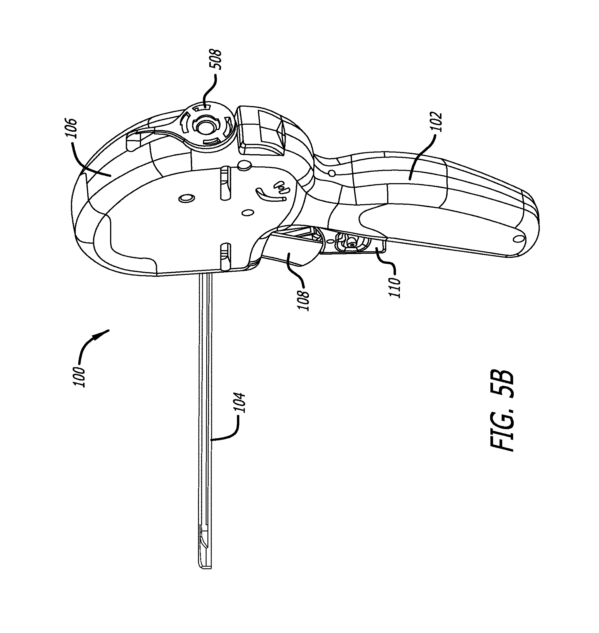
[0030] FIG. 5B is a view of a second embodiment of a delivery device;
[0031] FIG. 5C is a view of a third embodiment of a delivery device;
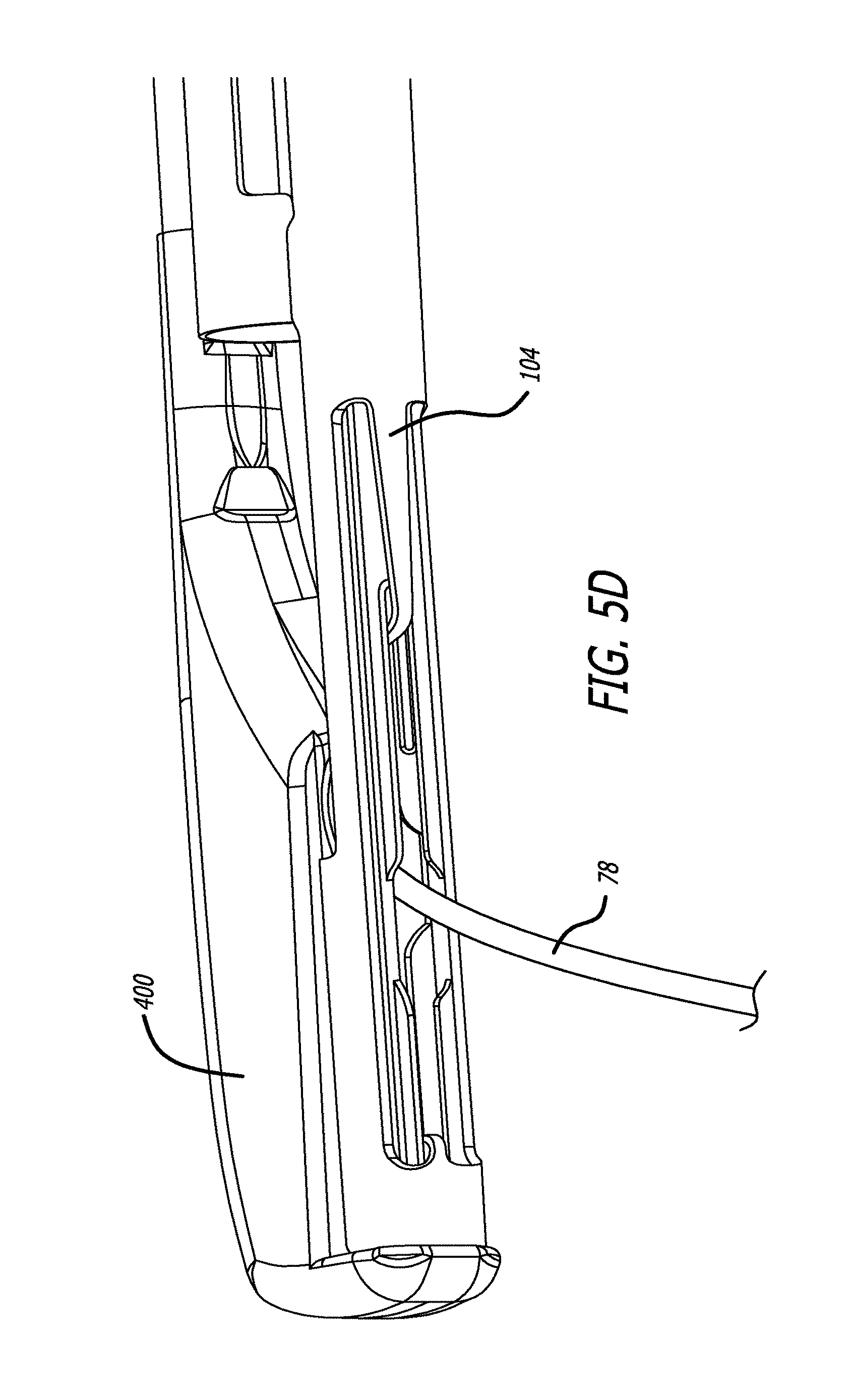
[0032] FIG. 5D is a view of a fourth embodiment of a delivery device;
[0033] FIGS. 6A-B are cross-sectional views, depicting one incontinence treatment approach;
[0034] FIG. 6A is a view of a first treatment approach;
[0035] FIG. 6B is a view of a second treatment approach;
[0036] FIG. 7 is a cross-sectional view depicting of another incontinence treatment approach;
[0037] FIGS. 8A-B are cross-sectional views, depicting yet further approaches to treatment;
[0038] FIG. 8A is a view of a first further treatment approach;
[0039] FIG. 8B is a view of a second further treatment approach;
[0040] FIGS. 9A-B are cross-sectional views, depicting still further treatment approaches;
[0041] FIG. 9A is a view of a first further treatment approach;
[0042] FIG. 9B is a view of a second further treatment approach;
[0043] FIG. 9C is a view of a third further treatment approach;
[0044] FIG. 10 is a side view, depicting an alternative anchor assembly;
[0045] FIG. 11 is a cross-sectional view, depicting use of the structure of FIG. 10 in a treatment approach;
[0046] FIG. 12 is a cross-sectional view, depicting a treatment approach involving the prostate;
[0047] FIGS. 13A-B are cross-sectional views, depicting yet further incontinence treatment approaches;
[0048] FIG. 13A is a view of a first further treatment approach;
[0049] FIG. 13B is a view of a second further treatment approach;
[0050] FIGS. 14A-B depict alternative approaches to treatment;
[0051] FIG. 14A is a view of a first alternative approach; and
[0052] FIG. 14B is a view of a second alternative approach.
DETAILED DESCRIPTION OF THE PREFERRED EMBODIMENTS
[0053] Turning now to the figures, which are provided by way of example and not limitation, the present disclosure is directed to a device configured to deliver an anchor assembly within a patient's body for treatment purposes. The disclosed apparatus can be employed for various medical purposes including but not limited to treating incontinence.
[0054] In an aspect of the present invention, one portion of an anchor assembly or implant is positioned and implanted against a first section of anatomy. A second portion of the anchor assembly or implant is then positioned and implanted adjacent to a second section of anatomy for the purpose of retracting, lifting, compressing, stabilizing, supporting or repositioning the second section of anatomy with respect to the first section of anatomy as well as for the purpose of retracting, lifting, compressing, stabilizing, supporting or repositioning the first section of anatomy with respect to the second section of anatomy. It is also to be recognized that both a first and second portion of the anchor assembly can be configured to accomplish the desired retracting, lifting, compressing, stabilizing, supporting or repositioning of anatomy due to tension supplied during delivery via a connector assembly affixed to the first and second portions of the anchor assembly or implant.
[0055] Turning to FIGS. 1-3, various features of urological anatomy of a human subject are presented. With specific reference to FIGS. 1 and 2, in a male subject, the prostate gland PG is a walnut-sized muscular gland found in a male and located adjacent the urinary bladder UB. The urethra UT runs through the prostate gland PG. The prostate gland PG secretes fluid that protects and nourishes sperm. The prostate also contracts during ejaculation of sperm to expel semen and to provide a valve to keep urine out of the semen. A capsule C surrounds the prostate gland PG. The portion of the urethra UT extending through the prostate PG is referred to as the prostatic urethra PU. Distal to the prostatic urethra PU are the membranous urethra MU and bulbous urethra BU portions of the urethra UT. The membranous urethra MU is the most narrow, shortest and least dilatable portion of the urethra. It extends between an apex of the prostate PG to the bulb of the urethra UT.
[0056] The urinary bladder UB holds urine. The vasa deferentia VD define ducts through which semen is carried and the seminal vesicles SV secrete seminal fluid. The rectum R is the end segment of the large intestine and through which waste is dispelled. The urethra UT carries both urine and semen out of the body. Thus, the urethra is connected to the urinary bladder UB and provides a passageway to the vasa deferentia VD and seminal vesicles SV.
[0057] Further, the trigone T is a smooth triangular region of the bladder. It is sensitive to expansion and signals the brain when the urinary bladder UB is full. The verumontanum VM is a crest in the wall of the urethra UT where the seminal ducts enter. The prostatic urethra is the section of the urethra UT which extends through the prostate.
[0058] In a female subject (FIG. 3), the urinary bladder UB also holds urine and extending from the bladder is the urethra UT. The pelvic floor muscle PFM supports the female urinary bladder UB and the position of the urethra UT. The uterus US and vagina V as well as the rectum R are positioned posteriorly of the anatomy defining the urinary system.
[0059] In one embodiment (See FIG. 4), the anchor assembly 60 is embodied in a tissue anchor. The tissue anchor is an implant assembly that includes one tubular member, referred to as the capsular anchor or, more generally, distal anchor 70. The distal anchor 70 is preferably connected by a suture (preferably polyester) 78 to a slotted, flattened-tubular member (preferably comprised of stainless steel), referred to as the urethral anchor or proximal anchor 84. In one specific, non-limiting embodiment, the distal anchor 70 is comprised of an electro-polished Nitinol (nickel titanium alloy SE508, 55.8% nickel) tube.
[0060] The tissue anchor is designed to be useable in physician's clinical office environment (in contrast to requiring a hospital environment) with a delivery tool. The delivery tool is used through a 19 F sheath in one preferred embodiment, while in another embodiment a sheath size of 21 F is employed. In this suture-based, tissue technique, a needle delivery mechanism is used to implant a nitinol distal anchor 70 and attached suture 78. Once the distal anchor 70 and attached suture 78 have been deployed, with the needle retracted and the suture 78 tensioned, the slotted anchor 84 is pushed by the delivery tool and captures the suture 78 transverse to the anchor axis. The flattened portion of the anchor 84 allows the anchor to be held by the tool without rotating so that it will stay oriented properly to ensure the suture enters the space between the prongs. In many of the illustrated embodiments, the seating region in the slotted anchor for the suture is shown in approximately the midpoint of the slotted anchor but it is within the scope of the present invention to locate the seating region closer to one end or the other of the anchor in order to prevent the ends of the prongs of the anchor from digging into tissue after implantation but rather sit more parallel to the tissue, if so desired.
[0061] The nitinol tube can be attached to a USP size 0 PET (Poly Ethylene Terephthalate) monofilament suture 78 by thermally forming the suture to locking features on the anchor 70. Referring again to the suture itself, the PET suture is a round monofilament extrusion/pulltrusion composed of a grade 8816 polyethylene terephthalate. Typically, the base material for the suture is annealed at approximately 375 degrees Fahrenheit for approximately 5 minutes in a straight condition. In one non-limiting embodiment, the PET suture 78 has a diameter of 0.015 inches and a tensile strength greater than or equal to 12.7 pounds. It is preferred that the tensile strength be about 6 pounds or greater.
[0062] In one embodiment, the proximal anchor 84 is a 316L stainless steel flattened tube that is slotted, electro-polished, and passivated. The anchor is depicted in the figures with a flat surface on the top or bottom but it is within the scope of the present invention that only one of the surfaces be flat and that the surface(s) do not have to be true flat but rather could have a slight dip or protrusion on the flattened surfaces. The slotted anchor 84 includes prongs 96 that grip and deform the suture 78 in the seating region 98 between the spaced prongs 96. It is to be recognized that rather than defining mirrored images, in one or more of the embodiments disclosed herein, the seating region can be formed by staggered structure or one prong can have a longer area defining seating structure than an opposing prong to provide an effective engagement for a particular suture or connector design. The prongs 96 are quite stiff and robust therefore subject to minimal to no deflection. In particular preferred embodiments, the prongs or overall width of the anchor adjacent the seating region 98 expands, after a connector has been seated in the seating region, less than about 0.002 inches (i.e., less than about five percent), more preferably less than about 0.001 inches (i.e., less than about two and half percent). In particular preferred embodiments, the prongs or overall width of the anchor adjacent the ends of the prongs 96 expands, after a connector has been seated in the seating region, less than about 0.0065 inches (i.e., less than about seventeen percent), more preferably less than about 0.006 inches (i.e., less than about fifteen percent). Due to its particular configuration, the slotted anchor 84 also requires less force to deploy onto a suture 78. Being relatively stiff, the prongs 96 of the slotted anchor 84 are significantly more resistant to bending. The four individual edges/faces (two on each prong 96) of the slotted anchor 84 disrupt the surface of the suture 78, both biting into the suture 78 as well as compressing the suture 78 between the slotted prongs 96, including sometimes melting the suture locally due to the pressure and heat created during deployment of the slotted anchor onto the suture. The reduced area of contact provided by this structure as well as multiple planes of engagement of the anchor slot to the connector strengthens connections and prevents inadvertent separation. Additionally, the narrow width between the prongs 96 is substantially smaller than the connector diameter, with the purpose to allow the stiffer prongs to slightly elastically expand over the connector and contribute to anchor retention by means of compression but not intended to receive the connector into this relief slot, which is positioned proximal to the seating portion 98. It is beneficial in some circumstances however for the slotted anchor to be pushed far enough on to the connector such that the connector becomes at least partially seated in the slot inception relief slot so that it becomes pinched and/or wedged. In this circumstance, a two-part compression slot is created wherein the short, narrow part of the slot ensures a good mechanical interlock but may compromise the strength of the suture locally and the second wider part is ensures a good mechanical interlock but without any compromise in the strength of the suture. Notably, the outwardly stepped slot width also has a dimension smaller than the connector diameter, and receives the connector with some interference.
[0063] The prongs 96 can be formed from a wide (or flattened) tubular structure. The wider and smoother prongs 96 of the anchor 84 assist in preventing the prongs 96 from irritating and/or damaging tissue, which is more likely to occur with a thinner and pointier leg structure. Further, in one embodiment, the slot in the anchor 84 is configured to create registering and aligning surfaces to the delivery tool (not shown). In several embodiments, the two inner surfaces of the prongs 96 of the slotted anchor 84 are configured as corresponding inwardly facing U-shapes. In this configuration, the inner surfaces of the prongs 96 bite into the suture 78. In still other embodiments, the two inner surfaces of the prongs 96 of the slotted anchor 84 are configured to present a notched geometry. In still other embodiments, the inner surfaces of the prongs are configured with burrs, roughened edges, serrations, etc. to enhance their ability to retain the connector.
[0064] Referring now to FIGS. 5A-D, there is shown one embodiment of a delivery device 100. This device is configured to include structure that is capable of both gaining access to an interventional site as well as assembling and implanting one or more anchor assemblies or implants within a patient's body. The delivery device 100 can be configured to assemble and implant a single anchor assembly or implant. The device is further contemplated to be compatible for use with a 19 F sheath. The device additionally includes structure configured to receive a conventional remote viewing device (e.g., an endoscope) so that the steps being performed at the interventional site can be observed.
[0065] Prior to use of the present device 100, a patient typically undergoes a five day regiment of antibiotics. A local anesthesia can be employed for the interventional procedure. A combination of an oral analgesic with a sedative or hypnotic component can be ingested by the patient. Moreover, topical anesthesia such as lidocaine liquids or gel can be applied to the bladder and urethra.
[0066] The anchor delivery device 100 includes a handle assembly 102 connected to an elongate tissue access assembly 104. The elongate tissue access assembly 104 houses components employed to construct an anchor assembly and is sized to fit into a 19 F cystosopic sheath for patient tolerance during a procedure in which the patient is awake rather than under general anesthesia. The tissue access assembly is stiff to allow manual exploration of tissue at an interventional site by leveraging or pushing the handle assembly 102.
[0067] The anchor delivery device 100 further includes a number of subassemblies. A handle case assembly 106 including mating handle parts, which form part of the handle assembly 102. The handle assembly 102 is sized and shaped to fit comfortably within an operator's hand and can be formed from conventional materials. Windows can be formed in the handle case assembly 106 to provide access to internal mechanisms of the device so that a manual override is available to the operator in the event the interventional procedure needs to be abandoned.
[0068] In one embodiment, the delivery device 100 is equipped with various activatable members, which facilitate assembly and delivery of an anchor assembly at an interventional site. A needle actuator 108 is provided and as described in detail below, effectuates the advancement of a needle assembly (loaded with a first component of an anchor assembly) to an interventional site. In a preferred embodiment, the needle assembly has a needle that moves through a curved trajectory and exits the needle housing in alignment with a handle element, and in particular embodiments, in alignment with the grip. In various other embodiments, the needle housing is oriented such that the needles exits the housing at either the two o'clock or ten o'clock positions relative to a handle grip that is vertical. A needle retraction lever assembly 110 is also provided and when actuated causes the needle assembly to be withdrawn and expose the first anchor component. This action and the structure involved is also described in detail below. Finally, the delivery device 100 is equipped with a rear or proximal anchor actuator assembly 112, which as fully described below, upon actuation, accomplishes assembly of a second component to the anchor assembly and release of the anchor assembly at the interventional site.
[0069] In one particular, non-limiting use in treating incontinence, the elongate tissue access portion 104 of a delivery device is placed within a urethra (UT) leading to a urinary bladder (UB) of a patient. In one approach, the delivery device can be placed within an introducer sheath (not shown) previously positioned in the urethra or alternatively, the delivery device can be inserted directly within the urethra. When employing an introducer sheath, the sheath can be attached to a sheath mount assembly (described below). The patient is positioned in lithotomy. The elongate portion 104 is advanced within the patient until a leading end thereof reaches a target tissue.
[0070] As shown in FIGS. 5A-B, the delivery device is at this stage configured in a ready state. The needle actuator 108 and the needle retracting lever 110 are in an inactivated position.
[0071] Upon depression of the needle actuator 108, the needle assembly 230 is advanced from within the elongate member 104 (See FIG. 5C). The needle assembly can be configured so that it curves back toward the handle as it is ejected. In use, the needle assembly is advanced through and beyond a target tissue. Spring deployment helps to ensure the needle passes swiftly through the tissue. In one approach, the needle is made from Nitinol tubing and can be coated with Parylene N. Such a coating helps compensate for frictional or environmental losses (e.g., wetness), which may degrade effectiveness of needle penetration.
[0072] After complete depression of the needle actuator 108 and the unlocking of the needle retraction lever 110, the needle retraction lever 110 can be actuated. Such action results in a withdrawal of the needle assembly 230, leaving the connector 78 of an anchor assembly in an extended position (See FIG. 5D). In one embodiment, the needle 230 is withdrawn further than its original position within the device pre-deployment.
[0073] The proximal anchor actuator assembly 112 is configured at a back end of the casing 106. Actuation of the proximal anchor actuator 112 results in causing the proximal anchor component 84 to engage the connector 78. It also accomplishes cutting a connector 78 to length. Within a patient's body, the anchor assembly is configured across anatomy within the interventional site. The urethra UT is thus stabilized, repositioned or its position is maintained due to the anchor assembly engaging the surrounding tissue. The urethra UT can also be modified using the anchor assemblies, such as by decreasing its size or cross-sectional profile.
[0074] Accordingly, an approach involving inserting a tissue suturing or anchoring device into the prostatic urethra UT transurethrally to displace or maintain positioning of the urethra UT is contemplated. The delivery device can also be inserted within the patient's body through an incision site. It is thus contemplated that the anchor delivery device 100 can be advanced through an incision site made in the front of the patient's body, or in the space behind the testicles in the male or through the vagina in a female. An approach originating through the rectum is also contemplated.
[0075] As an initial step, sagittal views of a patient's urethra, bladder and surrounding tissues can be taken using transabdominal or transrectal ultrasonography. In this way, the patient's anatomy can be assessed. In this regard, measurements can be taken to determine the various distances and spaces involved in an approach to treat incontinence. After assessing the anatomy, the elongate tissue access assembly 104 of an anchor delivery device (See FIGS. 5A-B) is advanced within the urethra UT or through an incision site.
[0076] Next, an anchor assembly can be deployed to stabilize, reposition, modify or hold in place the target urethra UT. As described above, the anchor delivery device accomplishes first deploying a distal anchor 70 and then assembles and attaches a proximal anchor component 84 onto a connector 78. The distal anchor 70 is implanted in anatomy having sufficient purchase. Although the above described tissue anchor matter is shown in a number of drawings relating to treating incontinence, it is to be recognized that various other embodiment of anchors can also be utilized in any of the treatment approaches (See for example, FIG. 10).
[0077] As stated, the present disclosure is intended to address all forms of incontinence. In treating Stress Urinary Incontinence (SUI), the fascia and pelvic muscles surrounding the urethra do not adequately hold the urethra UT in position. When intra-abdominal pressure increases, during events such as coughing or sneezing, the urethra can move downward in position, causing urine to leak. In one approach, an anchor assembly 60 including a distal anchor 70 attached to a second anchor 84 by a tensioned suture element 78 is used to stabilize, reposition and hold the urethra UT in the proper position.
[0078] As shown in FIGS. 6A-B in one treatment protocol, the distal anchor 70 is deployed anterior of the urethra UT, the suture 78 is tensioned, and then the proximal anchor 84 would be deployed in the urethra UT. After deployment, the proximal anchor 84 pulls the urethra UT upward based on the tension (FIG. 6A (before) and FIG. 6B (after)).
[0079] This approach would provide a treatment that is minimally invasive. The anchor assembly 60 is small and can be delivered transurethrally. The procedure may be performed in the office setting instead of an operating room. Also, side effects and complications from surgery, such as erosion, are reduced. In women, using a conventional sling can result in substantial mesh erosion.
[0080] In another approach (FIG. 7), the distal anchor 70 can also be deployed laterally relative to the urethra UT. The anchor assembly 60 would tension the urethra UT to stabilize it during increases or changes in intra-abdominal pressure.
[0081] Also, as shown in FIGS. 8A-B, the delivery device 100 could be placed in a low (posterior) position in the urethra UT initially, but the target exterior the urethra UT would be a high (anterior) position. Also, it is contemplated that the delivery device 100 or other instruments can be employed to manipulate tissue to achieve a desired, non-linear trajectory of the connector 60 through tissue defining the urethra UT (See FIG. 8B).
[0082] In women, the urethra UT is supported by pelvic floor fascia PFM (See FIG. 3). If this support is insufficient, the urethra UT can move downward at times of increased abdominal pressure leading to urinary incontinence. Devices, which lift the urethra UT towards the abdomen to improve continence, are thus contemplated. In particular, an anchor assembly 60 can be used to treat urinary incontinence by stabilizing, repositioning and/or lifting the urethra UT towards the abdomen, or otherwise stabilize or modify the urethra UT. This can be achieved through several approaches.
[0083] In a first approach (FIG. 9A), the connector 78 of an anchor assembly 60 is passed laterally through the anterior periurethral fascia APF and is anchored to lateral tissue or bone. Applying tension along the suture connector 78 would serve to lift the urethra UT towards the abdomen thus reducing incontinence in women in this approach. The suture would not enter the urethral lumen.
[0084] In an alternate approach (FIG. 9B), the connector 78 of an anchor assembly is passed laterally through the anterior periurethral fascia APF and anchored to lateral tissue or bone. Here, the suture connector 78 would pass through the urethral lumen UT. Applying tension along the suture 78 would serve to lift the urethra UT towards the abdomen thus reducing incontinence in women.
[0085] In yet another approach (FIG. 9C), the connector 78 of an anchor assembly 60 is anchored into anterior urethral fascia AUF. Another anchor assembly 60 would serve as a direct link from the fascia to the urethral lumen UT. Applying lateral tension to the sutures lifts the fascia towards the abdomen, which would, in turn, pull the suture connecting the fascia to the urethral lumen UT. As a result, the urethra UT would be pulled towards the abdomen thus reducing incontinence in women. Accordingly, a minimally invasive transurethral or laparoscopic approach is described, one where additional lift or purchase by passing the suture through the urethral lumen UT is suggested or alternatively, in men, the additional lift or purchase is achieved by passing through the prostate capsule.
[0086] It is also contemplated that incontinence can be treated using a sling device 560 (See FIG. 10). The sling device can include a mid-section defined by an elongate mesh structure 578. At each end of the mesh structure 578 there are extensions including barbs or anchors 584. The sling assembly 560 can be deployed into the prostate PG with both sling ends 584 on the prostate capsule C and with the exposed sling in urethra UT providing tissue stabilizing or repositioning (See FIG. 11). The sling 560 could be initially placed inside a hollow needle or other element and delivered into the tissue via a trocar. The sling assembly 560 could also be deployed through the prostate, with one sling end on the capsule C and the other sling end residing on the urethra UT to provide tissue repositioning or stabilizing. In a related treatment approach (See FIG. 12), an anchor assembly 60 can be configured across the prostate PG to aid in repositioning or stabilizing of the urethra UT to treat SUI. These approaches to treating urinary incontinence allow for minimally invasive surgical approaches and would be a cost effective, simple way to urinary incontinence.
[0087] Further, it is contemplated that the sling assembly 560 or anchor assembly 60 can include an anchor having a multi or staged barb component (See 590; FIG. 11) that could provide means for adjustment and custom tissue stabilizing or repositioning. Staged barbs 590 would allow tightening or length adjustment of the sling or anchor assemblies. Also, a wire or similar element could reside in the sling assembly 560 to provide increased column strength. An expandable balloon or other element could reside against the urethra UT to provide adjustable tissue compression. Alternatively, a urethral element can also be used which can twist or rotate to adjust implant length and provide adjustable tissue repositioning or stabilizing.
[0088] As shown in FIG. 12, one or more anchor assemblies 60 can be positioned across the prostate PG to treat incontinence. In this approach, the urethra UT is repositioned or stabilized by anchors providing forces on the prostate PG without physical contact with the urethra.
[0089] With reference now to FIGS. 13A-B, another approach involves deploying two anchor assemblies 60 in cross-pattern below the prostate PG to hold urethra UT upward in a correct or desired position. Another configuration would be to deploy anchor assembly 60 underneath the prostate PG to hold the urethra UT upward in the desired position (FIG. 13B). Multiple anchor assemblies 60 could also be used along length of urethra UT (FIG. 14A). Alternately, the anchor assembly 660 could be modified from a single monofilament to a multi-strand, splayable suture 678 with shared end connections (FIG. 14B).
[0090] It is to be recognized that the approaches depicted in at least FIGS. 6-9 and 13A-B can be utilized in the male treatment of the membranous urethra MU and the bulbous urethra BU (See also FIG. 2). That is, one or more anchor assemblies can be configured through and/or about the membranous and bulbous sections of the urethra UT to reconfigure, stabilize or change the size or shape of these sections of the urethra UT. By so specifically addressing the membranous urethra and bulbous urethra BU, in continence in males can be minimized.
[0091] Moreover, it is contemplated that the anchor assembly connector 78 could be replaced with a wider material, such as a biocompatible tape. The connector 78 could also be placed in a diagonal pattern, to provide greater area for the connector to interface with the urethra (See FIG. 14A).
[0092] Accordingly, the present invention contemplates both pushing directly on anchor portions of an anchor assembly as well as pushing directly upon the connector of the anchor assembly. Moreover, as presented above, the distal or first anchor component is advanced and deployed through a needle assembly and at least one component of the proximal or second anchor component is advanced and deployed from a housing portion of the anchor deployment device. Further, either a single anchor assembly or multiple anchor assemblies can be delivered and deployed at an intervention site by the deployment device. Additionally, a single anchor assembly component can for example, be placed on one side of a prostate or urethra while multiple anchor assembly components can be positioned along an opposite or displaced position of such anatomy. The number and locations of the anchor assemblies can thus be equal and/or symmetrical, different in number and asymmetrical, or simply asymmetrically placed. Moreover, drug delivery is both contemplated and described as a further remedy in BPH and over active bladder treatment as well as treating prostate cancer and prostatitis.
[0093] Once implanted, the anchor assembly of the present invention accomplishes desired tissue manipulation, approximation, compression or retraction as well as cooperates with the target anatomy to provide an atraumatic support structure.
[0094] Furthermore, in addition to an intention to cooperate with natural tissue anatomy, the present invention also contemplates approaches to accelerate healing or induce scarring. Manners in which healing can be promoted can include employing abrasive materials, textured connectors, biologics and drugs.
[0095] Additionally, it is contemplated that the components of the anchor assembly or selected portions thereof (of any of the anchor assemblies described or contemplated), can be coated or embedded with therapeutic or diagnostic substances (e.g. drugs or therapeutic agents). Again, in the context of treating a prostate gland, the anchor assembly can be coated or imbedded with substances such as 5-alpha-reductase inhibitors, which cause the prostate to decrease in size. Other substances contemplated include but are not limited to phytochemicals generally, alpha-la-adrenergic receptor blocking agents, smooth muscle relaxants, and agents that inhibit the conversion of testosterone to dihydrotestosterone. In one particular approach, the connector can for example, be coated with a polymer matrix or gel coating, which retains the therapeutic or diagnostic substance and facilitates accomplishing the timed release thereof. Additionally, it is contemplated that bacteriostatic coatings as well as analgesics and antibiotics for prostatitis and other chemical coatings for cancer treatment, can be applied to various portions of the anchor assemblies described herein. Such coatings can have various thicknesses or a specific thickness such that it along with the connector itself matches the profile of a cylindrical portion of an anchor member affixed to the connector. Moreover, the co-delivery of a therapeutic or diagnostic gel or other substances through the implant deployment device or another medical device (i.e. catheter), and moreover an anchor assembly including the same, is within the scope of the present invention as is radio-loading devices (such as a capsular or distal ends of implants for cancer or other treatment modalities). In one such approach, the deployment device includes a reservoir holding the gel substance and through which an anchor device can be advance to pick up a desired quantity of therapeutic or diagnostic gel substance.
[0096] It is to be recognized that the timing of the dual advancement of the needle and connector assemblies and subsequent relative motion between the assemblies is coordinated. That is, the needle assembly first provides access to an interventional site and then the connector assembly is left extending beyond a terminal end of the needle assembly through the relative motion of the needle and connector assemblies.
[0097] It is further contemplated that in certain embodiments, the anchor delivery device can include the ability to detect forces being applied thereby or other environmental conditions. Various sections of the device can include such devices and in one contemplated approach sensors can be placed along the needle assembly. In this way, an operator can detect for example, whether the needle has breached the target anatomical structure at the interventional site and the extent to which such breaching has occurred. Other sensors, which can detect particular environmental features, can also be employed such as blood or other chemical or constituent sensors. Moreover, one or more pressure sensors or sensors providing feedback on the state of deployment of the anchor assembly during delivery or after implantation are contemplated. For example, tension or depth feedback can be monitored by these sensors. Further, such sensors can be incorporated into the anchor assembly itself, other structure of the deployment device or in the anatomy.
[0098] Moreover, it is to be recognized that the foregoing procedure is reversible. In one approach, the connection of an anchor assembly can be severed and a proximal (or second) anchor component removed from the patient's body. For example, the physician can cut the connector and subsequently remove the one or both anchors previously implanted for example, in the patient's urethra.
[0099] An aspect that the various embodiments of the present invention provide is the ability to deliver an anchor assembly having a customizable length, each anchor assembly being implanted at a different location without having to remove the device from the patient. Other aspects of the various embodiments of the present invention are load-based delivery, of an anchor assembly, anchor assembly delivery with a device having integrated connector, (e.g. suture), cutting, and anchor assembly delivery with an endoscope in the device. The delivery device is uniquely configured to hold the suture with tension during delivery to help ensure that the first anchor component sits firmly against a tissue plane (e.g., the outer capsule of the prostate) and is held relatively firm as the second anchor component is attached to the connector and the delivery device. In this aspect, the needle assembly acting as a penetrating member is cooperatively connected to a mechanism, which pulls on the anchor while the needle assembly is retracted.
[0100] It is to be recognized that various materials are within the scope of the present invention for manufacturing the disclosed devices. Moreover, one or more components such as distal anchor, proximal anchor, and connector, of the one or more anchor devices disclosed herein can be completely or partially biodegradable or biofragmentable.
[0101] Further, as stated, the devices and methods disclosed herein can be used to treat a variety of pathologies in a variety of lumens or organs comprising a cavity or a wall. Examples of such lumens or organs include, but are not limited to urethra, bowel, stomach, esophagus, trachea, bronchii, bronchial passageways, veins (e.g. for treating varicose veins or valvular insufficiency), arteries, lymphatic vessels, ureters, bladder, cardiac atria or ventricles, uterus, fallopian tubes, etc.
[0102] Finally, it is to be appreciated that the invention has been described herein with reference to certain examples or embodiments of the invention but that various additions, deletions, alterations and modifications may be made to those examples and embodiments without departing from the intended spirit and scope of the invention. For example, any element or attribute of one embodiment or example may be incorporated into or used with another embodiment or example, unless to do so would render the embodiment or example unpatentable or unsuitable for its intended use. Also, for example, where the steps of a method are described or listed in a particular order, the order of such steps may be changed unless to do so would render the method unpatentable or unsuitable for its intended use. All reasonable additions, deletions, modifications and alterations are to be considered equivalents of the described examples and embodiments and are to be included within the scope of the following claims.
[0103] Thus, it will be apparent from the foregoing that, while particular forms of the invention have been illustrated and described, various modifications can be made without parting from the spirit and scope of the invention.
* * * * *
D00000
D00001
D00002
D00003
D00004
D00005
D00006
D00007
D00008
D00009
D00010
D00011
D00012

XML
uspto.report is an independent third-party trademark research tool that is not affiliated, endorsed, or sponsored by the United States Patent and Trademark Office (USPTO) or any other governmental organization. The information provided by uspto.report is based on publicly available data at the time of writing and is intended for informational purposes only.
While we strive to provide accurate and up-to-date information, we do not guarantee the accuracy, completeness, reliability, or suitability of the information displayed on this site. The use of this site is at your own risk. Any reliance you place on such information is therefore strictly at your own risk.
All official trademark data, including owner information, should be verified by visiting the official USPTO website at www.uspto.gov. This site is not intended to replace professional legal advice and should not be used as a substitute for consulting with a legal professional who is knowledgeable about trademark law.