Eyelash Application System
Schroeder; Sandi
U.S. patent application number 16/404705 was filed with the patent office on 2019-08-22 for eyelash application system. The applicant listed for this patent is Sandi Schroeder. Invention is credited to Sandi Schroeder.
| Application Number | 20190254374 16/404705 |
| Document ID | / |
| Family ID | 67617165 |
| Filed Date | 2019-08-22 |


| United States Patent Application | 20190254374 |
| Kind Code | A1 |
| Schroeder; Sandi | August 22, 2019 |
Eyelash Application System
Abstract
The eyelash application system having a casing for holding a plurality of eyelashes. Each of the locations for receiving cartridges in the casing having a cross or plus shaped recess for receiving a corresponding cross or plus shaped extrusion on one side of an eyelash cartridge for securing the cartridge to the casing. Each cartridge is further provided with a ridge for securing eyelashes to the cartridge. The lashes are not merely sitting on the cartridge, the lashes are retained within the walls of the ridge which secures the lashes in place and does not allow the lashes to slide, fall, or blow off the top flat surface of the cartridge. The ridge and cartridge mating structures serve to securely retain and locate the eyelash cartridge within the casing provider for more securement during transportation and resulting in less damage to the eyelashes.
| Inventors: | Schroeder; Sandi; (Los Angeles, CA) | ||||||||||
| Applicant: |
|
||||||||||
|---|---|---|---|---|---|---|---|---|---|---|---|
| Family ID: | 67617165 | ||||||||||
| Appl. No.: | 16/404705 | ||||||||||
| Filed: | May 6, 2019 |
Related U.S. Patent Documents
| Application Number | Filing Date | Patent Number | ||
|---|---|---|---|---|
| 14936255 | Nov 9, 2015 | 10278441 | ||
| 16404705 | ||||
| 16004178 | Jun 8, 2018 | |||
| 14936255 | ||||
| 62516691 | Jun 8, 2017 | |||
| Current U.S. Class: | 1/1 |
| Current CPC Class: | A41G 5/02 20130101 |
| International Class: | A41G 5/02 20060101 A41G005/02 |
Claims
1. An eyelash application system comprising: a casing with one or more cartridge locations for receiving cartridges; each casing having a shaped recess for receiving a corresponding shaped extrusion; one or more cartridges; each cartridge having a shaped extrusion for insertion into a corresponding shaped extrusion; at least one cartridge secured within a cartridge location; and the extrusion of the cartridge and the recess of the cartridge location engaging to securely retain the cartridge in the cartridge location and to the casing
2. The eyelash application system of claim 1, wherein the casing has four locations for receiving cartridges.
3. The eyelash application system of claim 1, wherein the extrusion on the cartridge is cross or plus shaped; and the recess on the casing is cross or plus shaped.
4. The eyelash application system of claim 1, wherein the cartridge location comprises, a box shaped space having an open top side; a solid bottom side having a recess for receiving a corresponding shaped extrusion on one side of an eyelash cartridge, two side walls; a back wall; and a front, partial wall, having a height less than that of the other three walls.
5. The eyelash application system of claim 5, wherein the extrusion on the cartridge is cross or plus shaped; and the recess on the casing is cross or plus shaped.
6. The eyelash application system of claim 1, wherein the cartridge is further comprised of a cartridge recess providing a location for receiving a corresponding extrusion for removing the cartridges secured to the casing in the cartridge location by the corresponding shaped extrusion and shaped extrusion recess.
7. The eyelash application system of claim 6, further comprising in combination an applicator/tweezer device the applicator/tweezer having a rounded proximal end; a two-pronged distal end; and a rigid member; the proximal end is defined by the rounded portion and is connected to the distal end by the rigid member.
8. The eyelash application system of claim 7, wherein the proximal end is formed with a smaller cross-section than the distal end.
9. The eyelash application system of claim 7, wherein each eyelash cartridge is loaded with an eyelash strip; the cartridge includes an open interior section or cartridge recess so that a user may grasp the eyelash cartridge by inserting one of the prongs of the applicator/tweezer into the open interior section or cartridge recess of the eyelash cartridge.
10. The eyelash application system of claim 9, wherein both of the prongs located on the distal end of the applicator/tweezer engage the lashes with the cartridge recess of each eyelash cartridge; once the applicator/tweezer has one or two eyelash cartridges with eyelashes attached, a user would then proceed to press the eyelash on at the desired location; and the eyelash would then remain and be retained to the face by glue, and the used eyelash cartridge is discarded or a new eyelash applied for later use.
11. The eyelash application system of claim 1, wherein the cartridge is further comprised of a ridge for the eyelash to be mounted, retained, and stored.
12. The eyelash application system of claim 11, wherein the ridge is curved with a smaller diameter than the eyelash allowing the eyelash to overhang the ridge.
13. The eyelash application system of claim 12, wherein the eyelash includes lashes, a band, and an adhesive; the lashes are mounted to the band and extend out away from the band; the lashes can fan out radially and be curved upward from a plane defined by the band; the band is in direct contact with the adhesive; and the adhesive covers the entire band and extend beyond the ends of the band.
14. The eyelash application system of claim 12, wherein the eyelash strip is provided on the eyelash cartridge as a one quarter, two thirds, or a full eyelash strip.
15. The eyelash application system of claim 7, wherein the cartridge has a cartridge mating structure defined as a cartridge recess; the cartridge mating surface is a cartridge recess that is configured to mirror the pronged protrusion of the applicator/tweezer and to be joined or fitted to the applicator/tweezer mating structures, one of the prongs; the applicator/tweezer mating structures is a protrusion or prong that narrows toward the proximal end, the corresponding cartridge mating structures will be a cartridge recess that also narrows toward the proximal end of the applicator/tweezer.
16. The eyelash application system of claim 15, wherein the cartridge mating structures as well as the applicator mating structures either taper toward or away from the proximal end; or have no taper toward or away from the proximal end.
Description
FEDERALLY SPONSORED RESEARCH
[0001] Not Applicable
SEQUENCE LISTING OR PROGRAM
[0002] Not Applicable
TECHNICAL FIELD OF THE INVENTION
[0003] The present invention relates in general to systems and methods for personal care. More specifically, the present invention relates to systems and methods for personal care, more partially for handling, storing, and applying false eyelashes.
BACKGROUND OF THE INVENTION
[0004] People around the world use products to enhance their appearance. All forms of cosmetics are used in the fashion, medical, and entertainment industries. False eyelashes and eyelash extensions are a commonly used technique for enhancing or augmenting the appearance of the eye.
[0005] Current methods for applying, storing, and handling false eyelashes present many problems that range from deleterious health consequences to difficulty in handling requiring a high degree of skill. Health consequences can result from the false eyelashes coming into contact with bacteria or other contagion eventually infecting the eye. This can happen when tools are improperly used or sanitized. This can also happen when an adhesive is applied in an unsanitary way.
[0006] Difficulty in applying false eyelashes can result from the awkward use of a delicate tweezer or even from attempting to apply the false eyelash with the naked finger tips. It is common for the false eyelash to be applied further from the base of the real eyelash than desirable, or with too much glue or adhesive.
[0007] Solutions have been long sought but prior developments have not taught or suggested any solutions that provide a comprehensive answer to these difficulties, and solutions to these problems have long eluded those skilled in the art. Thus there remains a considerable need for devices and methods that allow the application of false eyelashes in an easy intuitive way with minimal expertise or experience.
SUMMARY OF THE INVENTION
[0008] The eyelash application system of the present invention teaches an improved housing system comprised of a casing with one or more locations for receiving cartridges. Each of the receiving cartridges in the casing is further defined by a cross or plus shaped recess for receiving a corresponding cross or plus shaped extrusion on one side of an eyelash cartridge for securing the cartridge to the casing. Additionally, each cartridge is further provided with a ridge for securing eyelashes to the cartridge.
[0009] The cartridge mating structures is formed as a cartridge recess as illustrated, protrusions, or a combination thereof. In the present invention and figures, the cartridge mating surface is a cartridge recess that is configured to mirror the pronged protrusion of the applicator/tweezer and to be joined or fitted to the applicator/tweezer mating structures, one of the prongs. That is when one of the applicator/tweezer mating structures is a protrusion or prong that narrows toward the proximal end, the corresponding cartridge mating structures will be a cartridge recess that also narrows toward the proximal end 18 of the applicator/tweezer.
[0010] The applicator mating structures or prongs are configured to interlock with the cartridge mating structures or recesses where both the cartridge mating structures and the applicator mating structures have surfaces that are in continuous direct contact. It is contemplated that the applicator mating structures can deform into or around the cartridge mating structures and provide a click when the applicator mating structures or prong is fully engaged with the cartridge mating structures or recesses.
[0011] It has been discovered that utilizing the applicator/tweezer mating structures interlocking with the eyelash cartridge mating structures, the eyelash strip is locked in to an exacting position with regard to the applicator/tweezer and enables users to more quickly and intuitively apply the eyelash strip.
[0012] The cartridge is also depicted as having cartridge mating structures defined as a cross/plus shaped extrusion. In the present invention and figures, the cross/plus shaped extrusion is configured to mirror the cross/plus shaped recess located in each cartridge location of the casing, and to be joined or fitted to cross/plus shaped recess in a casing cartridge location.
[0013] In the present invention, not only has an improvement been made in how the cartridges are attached to the casing, but an improvement has been made in how the eyelashes attach to the cartridge. In the present invention, the lashes are not merely sitting on the cartridge or attached to the cartridge with adhesive alone, the lashes are retained within the walls of the ridge which secures the lashes in place and does not allow the lashes to slide, fall, or blow off the top flat surface of the cartridge.
[0014] The ridge and cartridge mating structures serve to securely retain and locate the eyelash cartridge within the casing provider for more securement during transportation and resulting in less damage to the eyelashes, which are prone to fall of the cartridges in previous prior art inventions or be jostled around resulting in bent or damages lashes, or cartridges that have rotated out of positon and can not be easily secured by a tweezers for use.
BRIEF DESCRIPTION OF THE DRAWINGS
[0015] The accompanying drawings, which are incorporated herein and form a part of the specification, illustrate the present invention and, together with the description, further explain the principles of the invention and to enable a person skilled in the pertinent art to make and use the invention.
[0016] FIG. 1 is a perspective view of the housing casing of the eyelash application system of the present invention.
[0017] FIG. 2 is as close up perspective view of the housing casing of the eyelash application system of the present invention illustrating an empty casing cartridge location and a casing cartridge location filled with a cartridge.
[0018] FIG. 3 is a top plane view of the housing component of the eyelash application system of the present invention.
[0019] FIG. 4 is a front side plane view of the housing casing of the eyelash application system of the present invention illustrating cartridges as present for removal by a tweezers.
[0020] FIG. 5 is a side plane view of the housing casing of the eyelash application system of the present invention.
[0021] FIGS. 6-7 are side plane views of the housing casing of the eyelash application system of the present invention.
[0022] FIGS. 8-9 are top and side plane views of the tweezer taught by the present invention.
[0023] FIGS. 10-11 are front and back perspective views of the tweezer taught by the present invention.
[0024] FIG. 12 is a perspective view of the cartridge of the present invention illustrating the ridge and cross/plus sign extrusion.
[0025] FIG. 13 is a bottom planar view of the cartridge of the present invention illustrating the cross/plus sign extrusion.
[0026] FIG. 14 is a side-bottom perspective view of the cartridge of the present invention illustrating the ridge and cross/plus sign extrusion.
[0027] FIG. 15 is a front-bottom perspective view of the cartridge of the present invention illustrating the cartridge recess and cross/plus sign extrusion.
DETAILED DESCRIPTION OF THE INVENTION
[0028] In the following detailed description of the invention of exemplary embodiments of the invention, reference is made to the accompanying drawings (where like numbers represent like elements), which form a part hereof, and in which is shown by way of illustration specific exemplary embodiments in which the invention may be practiced. These embodiments are described in sufficient detail to enable those skilled in the art to practice the invention, but other embodiments may be utilized and logical, mechanical, electrical, and other changes may be made without departing from the scope of the present invention. The following detailed description is, therefore, not to be taken in a limiting sense, and the scope of the present invention is defined only by the appended claims.
[0029] In the following description, specific details are set forth to provide a thorough understanding of the invention. However, it is understood that the invention may be practiced without these specific details. In other instances, well-known structures and techniques known to one of ordinary skill in the art have not been shown in detail in order not to obscure the invention. Referring to the figure, it is possible to see the various major elements constituting the apparatus of the present invention.
[0030] The eyelash application system is described in sufficient detail to enable those skilled in the art to make and use the eyelash application system and provide numerous specific details to give a thorough understanding of the eyelash application system; however, it will be apparent that the eyelash application system may be practiced without these specific details.
[0031] In order to avoid obscuring the eyelash application system, some well-known system configurations are not disclosed in detail. Likewise, the drawings showing embodiments of the system are semi-diagrammatic and not to scale and, particularly, some of the dimensions are for the clarity of presentation and are shown greatly exaggerated in the drawing figures. Generally, the eyelash application system is operated in any orientation.
[0032] For expository purposes, the term "horizontal" as used herein is defined as a plane parallel to the bottom plane or bottom surface of the cartridge, regardless of its orientation. The term "vertical" refers to a direction perpendicular to the horizontal as just defined. Terms, such as "above", "below", "bottom", "top", "side", "higher", "lower", "upper", "over", and "under", are defined with respect to the horizontal plane. The term "system" means an apparatus or a method based on the context in which it is used.
[0033] Now referring to FIGS. 1-15, one embodiment of the eyelash application system is shown. FIG. 1 is a perspective view of the housing system 1 of the eyelash application system of the present invention. The housing system 1 is comprised of a casing 3 with one or more locations for receiving cartridges 4. In the exemplary embodiment, each of the four locations for receiving cartridges 4 in the casing 3 is further defined by a cross or plus shaped recess 7 for receiving a corresponding cross or plus shaped extrusion 6 on one side of an eyelash cartridge 4.
[0034] FIG. 2 is as close up perspective view of the housing casing of the eyelash application system of the present invention illustrating an empty casing cartridge location and a casing cartridge location filled with a cartridge. In this representation, the location for receiving cartridges 4 is clearly defined as a box having an open top side, a solid bottom side having a cross or plus shaped recess 7 for receiving a corresponding cross or plus shaped extrusion 6 on one side of an eyelash cartridge 4, two side walls and a back wall, and a front, partial wall, having a height less than that of the other three walls.
[0035] FIG. 3 is a top plane view of the housing component of the eyelash application system of the present invention illustrating four locations for receiving cartridges 4, each location filled by a cartridge 4 holding an eyelash 2. FIG. 4 is a front side plane view of the housing casing 3 of the eyelash application system of the present invention illustrating cartridges 4 as present for removal by a tweezers 8, where a cartridge recess 9 provides a location for receiving a tweezer cartridge extrusion 10 for removing the cartridges 4 secured to the casing 3 by the corresponding cross or plus shaped extrusions 6 and cross or plus shaped extrusion recesses 7.
[0036] FIG. 5 is a side plane view of the housing casing 3 of the eyelash application system of the present invention. FIGS. 6-7 are side plane views of the housing casing 3 of the eyelash application system of the present invention. It would be recognized by a person of ordinary skill in the art that each casing 3 could hold any number of eyelash cartridges 4, and that the number and size of the eyelash cartridges 4 will vary based on the size of the eyelashes 2 place and retained by the eyelash cartridges 4. The drawings are illustrative only for the most common sizes and combinations of lashes 2, but the size and number of cartridges 4 intended to vary in each casing 3.
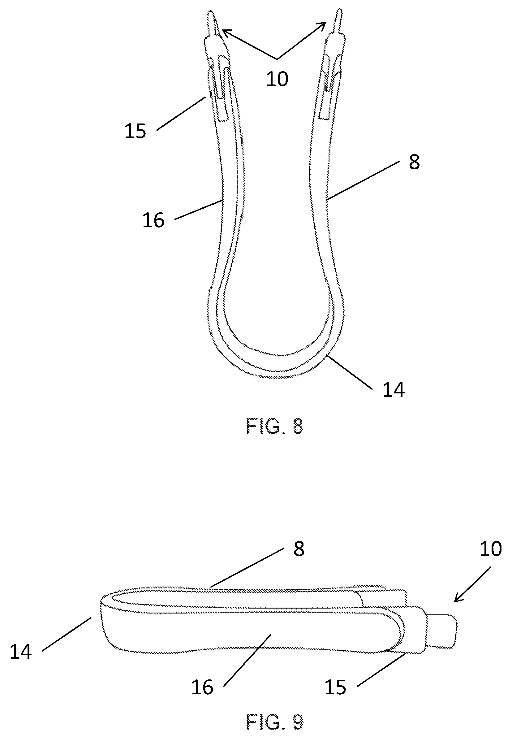
[0037] FIGS. 8-9 are top and side plane views of the tweezer taught by the present invention. FIGS. 10-11 are front and back perspective views of the tweezer taught by the present invention.
[0038] Referring now to FIGS. 8-11, an applicator/tweezer device 8 is shown in more detail. The applicator/tweezer 8 is shown having a rounded proximal end 14 and a two-pronged distal end 15. The proximal end 14 is the end that is closer to a user's wrist during operation while the distal end 15 is the end that is closer to a user's eye during operation. The proximal end 14 is formed with a smaller cross-section than the distal end 15 for greater mobility in the hand so that the distal end 15 is held in a number of different positions within the hand.
[0039] The proximal end 14 is defined by the rounded portion and is connected to the distal end 15 by a rigid member 16. This rigid member 16 provides a solid, no-slip location for positioning the fingers.
[0040] It has been discovered that providing the distal end 15 having a large width and surface to handle reduces the skill requirement for use. The large width and surface allows the applicator/tweezer 8 to be used by users with a lesser dexterity and allows users to fix multiple fingers along with the thumb on the applicator/tweezer 8 during use and utilize the larger muscles of the arm and wrist allowing for greater controllability and stability which can result in safer and more precise operation.
[0041] In use, a user would take the applicator/tweezer 8 and secure both of the prongs located on the distal end 15 and engage the lashes with the cartridge recess 9 of each eyelash cartridge 4 as shown in the figures. Once the applicator/tweezer 8 has one or two eyelash cartridges 4 with eyelashes 2 attached, a user would then proceed to press the eyelash on at the desired location. The eyelash 2 would then remain and be retained to the face by glue, and the used eyelash cartridge 4 is discarded or a new eyelash 2 applied for later use.
[0042] Referring now to FIGS. 1-3, each eyelash cartridge 4 is shown loaded with an eyelash strip 2. The cartridge 4 includes an open interior section or cartridge recess 9 so that a user may grasp the eyelash cartridge 4 with ease by inserting one of the prongs of the applicator/tweezer 8 into the open interior section or cartridge recess 9 of the eyelash cartridge 4.
[0043] The cartridge 4 provides a ridge 5 for the eyelash 2 to be mounted, retained, and stored. The ridge 5 is curved with a smaller diameter than the eyelash 2 allowing the eyelash 2 to overhang the ridge.
[0044] The eyelash 2 includes lashes, a band, and an adhesive. The lashes are mounted to the band and extend out away from the band. The lashes can fan out radially and be curved upward from a plane defined by the band.
[0045] The band is in direct contact with the adhesive. The adhesive covers the entire band and extend beyond the ends of the band. It has been discovered that it is advantageous to not require a user to manually apply the adhesive because it is easy for a user to apply more than required or to allow the adhesive to contact an unsanitary surface. Providing the adhesive already applied therefore increases uniformity of the adhesive as well as ensuring a non-infectious adhesive is used.
[0046] The eyelash strip 2 is provided on the eyelash cartridge 4 as a one quarter, two thirds, or a full eyelash strip 2. In some embodiments, it is contemplated that the eyelash 2 is formed as a quarter or two thirds strip negating the need for a user to trim the eyelash 2.
[0047] FIGS. 12-14 provide multiple views of the cartridge 4 of the present invention illustrating the ridge and cross/plus sign extrusion 6. The cartridge 4 is depicted as having cartridge mating structures defined as a cartridge recess 9. The cartridge mating structures is formed as a cartridge recess 9 as illustrated, protrusions, or a combination thereof. In the present invention and figures, the cartridge mating surface is a cartridge recess 9 that is configured to mirror the pronged protrusion 10 of the applicator/tweezer 8 and to be joined or fitted to the applicator/tweezer mating structures, one of the prongs. That is when one of the applicator/tweezer mating structures is a protrusion or prong that narrows toward the proximal end 14, the corresponding cartridge mating structures will be a cartridge recess 9 that also narrows toward the proximal end 18 of the applicator/tweezer 1.
[0048] It is contemplated that the cartridge mating structures as well as the applicator mating structures can taper toward or away from the proximal end 14. It is further contemplated that the cartridge mating structures as well as the applicator/tweezer mating structures can have no taper toward or away from the proximal end.
[0049] The applicator mating structures or prongs are configured to interlock with the cartridge mating structures or recesses where both the cartridge mating structures and the applicator mating structures have surfaces that are in continuous direct contact. It is contemplated that the applicator mating structures can deform into or around the cartridge mating structures and provide a click when the applicator mating structures or prong is fully engaged with the cartridge mating structures or recesses.
[0050] It has been discovered that utilizing the applicator/tweezer mating structures interlocking with the eyelash cartridge mating structures, the eyelash strip 2 is locked in to an exacting position with regard to the applicator/tweezer and enables users to more quickly and intuitively apply the eyelash strip 2.
[0051] On FIGS. 12-15, the cartridge 4 is also depicted as having cartridge mating structures defined as a cross/plus shaped extrusion 6. In the present invention and figures, the cross/plus shaped extrusion 6 is configured to mirror the cross/plus shaped recess 7 located in each cartridge location of the casing 3, and to be joined or fitted to cross/plus shaped recess 7 in a casing cartridge location.
[0052] In the present invention, not only has an improvement been made in how the cartridges 4 attached to the casing, but an improvement has been made in how the eyelashes 2 attach to the cartridge. Finally, on FIGS. 1-3, 12, and 14, a ridge 5 is shown on the cartridge 4 for securing an eyelash 2 in place. In the present invention, the lashes 2 are not merely sitting on the cartridge 4 or attached to the cartridge with adhesive alone, the lashes are retained within the walls of the ridge 5 which secures the lashes in place and does not allow the lashes to slide, fall, or blow off the top flat surface of the cartridge 4.
[0053] The ridge 5 and cartridge mating structures serve to securely retain and locate the eyelash cartridge 4 within the casing provider for more securement during transportation and resulting in less damage to the eyelashes 2, which are prone to fall of the cartridges in previous prior art inventions or be jostled around resulting in bent or damages lashes, or cartridges that have rotated out of positon and can not be easily secured by a tweezers 8 for use.
[0054] During application, the eyelash strip 2 has the adhesive in direct contact with a base of the user's eyelid. The adhesive directly couples the base with the band holding the lashes.
[0055] Two ways of applying the eyelash strip 2 are possible including one method applying the eyelash strip 2 above the eyelash of the user. The other method includes applying the eyelash strip 2 below the eyelash of the user. When the eyelash strip 2 is attached below the eyelash of the user, the band and the adhesive are not visible.
[0056] Thus, it is appreciated that the optimum dimensional relationships for the parts of the invention, to include variation in size, materials, shape, form, function, and manner of operation, assembly and use, are deemed readily apparent and obvious to one of ordinary skill in the art, and all equivalent relationships to those illustrated in the drawings and described in the above description are intended to be encompassed by the present invention.
[0057] Furthermore, other areas of art may benefit from this method and adjustments to the design are anticipated. Thus, the scope of the invention should be determined by the appended claims and their legal equivalents, rather than by the examples given.
* * * * *
D00000
D00001
D00002
D00003
D00004
D00005
D00006
D00007
D00008
XML
uspto.report is an independent third-party trademark research tool that is not affiliated, endorsed, or sponsored by the United States Patent and Trademark Office (USPTO) or any other governmental organization. The information provided by uspto.report is based on publicly available data at the time of writing and is intended for informational purposes only.
While we strive to provide accurate and up-to-date information, we do not guarantee the accuracy, completeness, reliability, or suitability of the information displayed on this site. The use of this site is at your own risk. Any reliance you place on such information is therefore strictly at your own risk.
All official trademark data, including owner information, should be verified by visiting the official USPTO website at www.uspto.gov. This site is not intended to replace professional legal advice and should not be used as a substitute for consulting with a legal professional who is knowledgeable about trademark law.