Adaptive Routing in a Box
Levy; Gil ; et al.
U.S. patent application number 15/896088 was filed with the patent office on 2019-08-15 for adaptive routing in a box. The applicant listed for this patent is Mellanox Technologies TLV Ltd.. Invention is credited to Barak Gafni, Gil Levy.
| Application Number | 20190253345 15/896088 |
| Document ID | / |
| Family ID | 67541228 |
| Filed Date | 2019-08-15 |


| United States Patent Application | 20190253345 |
| Kind Code | A1 |
| Levy; Gil ; et al. | August 15, 2019 |
Adaptive Routing in a Box
Abstract
A network box accepts packets from a network in ingress ports of a first tier of leaf switches, adaptively routes the packets from the leaf switches to a second tier of spine switches within the network box, statically routes the packets from the spine switches to designated egress ports of the leaf switches, and transmits the packets from the designated egress ports into the network.
| Inventors: | Levy; Gil; (Hod Hasharon, IL) ; Gafni; Barak; (Campbell, CA) | ||||||||||
| Applicant: |
|
||||||||||
|---|---|---|---|---|---|---|---|---|---|---|---|
| Family ID: | 67541228 | ||||||||||
| Appl. No.: | 15/896088 | ||||||||||
| Filed: | February 14, 2018 |
| Current U.S. Class: | 1/1 |
| Current CPC Class: | H04L 49/254 20130101; H04L 45/42 20130101; H04L 45/7453 20130101; H04L 49/1569 20130101; H04L 47/11 20130101; H04L 47/122 20130101; H04L 49/1515 20130101; H04L 47/125 20130101 |
| International Class: | H04L 12/717 20060101 H04L012/717; H04L 12/937 20060101 H04L012/937; H04L 12/803 20060101 H04L012/803 |
Claims
1. A network box connected in a communication network, comprising: a first tier of leaf switches having ingress ports and egress ports, configured to exchange packets; a second tier of spine switches having ingress ports and egress ports, and configured to exchange the packets with the first tier; and first packet processing circuitry, configured to adaptively route the packets from the first tier to the second tier; and second packet processing circuitry configured to statically route the packets from the second tier to the first tier.
2. The network box in accordance with claim 1, wherein the second packet processing circuitry is configured to route the packets using a hash function to identify a destination in the first tier.
3. The network box in accordance with claim 2, wherein the destination is one of the egress ports of one of the leaf switches.
4. The network box in accordance with claim 1, wherein the second packet processing circuitry is configured for: detecting a compromised ability of a congested spine switch to forward an arriving packet from another switch; and issuing a rerouting notification from the congested spine switch.
5. The network box in accordance with claim 4, wherein the rerouting notification is addressed individually to the other switch.
6. The network box in accordance with claim 4, wherein the arriving packet belongs to a flow, and wherein the first packet processing circuitry is configured to respond to the rerouting notification by avoiding routing the arriving packet and subsequently arriving packets belonging to the flow through the congested spine switch.
7. The network box according to claim 1, wherein each of the leaf switches is provided with an instance of the first packet processing circuitry and each of the spine switches is provided with an instance of the second packet processing circuitry, respectively.
8. The network box in accordance with claim 7, wherein each instance of the second packet processing circuitry is configured to use an identical hash function to identify a destination in the first tier.
9. The network box according to claim 1, further comprising a central processor that incorporates the first packet processing circuitry, and the second packet processing circuitry to control the leaf switches and the spine switches.
10. The network box in accordance with claim 1, further comprising a processor configured to transmit updated routing data to the spine switches and to synchronize a changeover to the updated routing data in the spine switches.
11. A method of communication comprising the steps of: in a network box accepting packets from a network in ingress ports of a first tier of leaf switches; adaptively routing the packets from the leaf switches to a second tier of spine switches within the network box; statically routing the packets from the spine switches to designated egress ports of the leaf switches; and transmitting the packets from the designated egress ports into the network.
12. The method in accordance with claim 11, wherein statically routing the packets is performed with a hash function to identify a destination in the first tier.
13. The method in accordance with claim 12, wherein each of the spine switches uses an identical hash function to statically route the packets.
14. The method in accordance with claim 11, further comprising the steps of: detecting a compromised ability of a congested spine switch to forward an arriving packet from another switch; and sending a rerouting notification from the congested spine switch.
15. The method in accordance with claim 14, further comprising addressing the rerouting notification individually to the other switch.
16. The method in accordance with claim 14, wherein the arriving packet belongs to a flow, further comprising responding to the rerouting notification by avoiding routing the arriving packet and subsequently arriving packets belonging to the flow through the congested spine switch.
17. The method in accordance with claim 11, further comprising the steps of: transmitting updated routing data to the spine switches and; synchronizing a changeover to the updated routing data in the spine switches.
Description
COPYRIGHT NOTICE
[0001] A portion of the disclosure of this patent document contains material that is subject to copyright protection. The copyright owner has no objection to the facsimile reproduction by anyone of the patent document or the patent disclosure, as it appears in the Patent and Trademark Office patent file or records, but otherwise reserves all copyright rights whatsoever.
BACKGROUND OF THE INVENTION
1. Field of the Invention
[0002] This invention relates to transmission of digital information over data networks. More particularly, this invention relates to performance of switched data networks.
2. Description of the Related Art
[0003] The meanings of certain acronyms and abbreviations used herein are given in Table 1.
TABLE-US-00001 TABLE 1 Acronyms and Abbreviations ARN Adaptive Routing Notification ASIC Application-Specific Integrated Circuit BGP Border Gateway Protocol CPU Central Processing Unit ECMP Equal Cost Multi-Path NIC Network Interface Card SRAM Static Random Access Memory
[0004] A challenge in modern network technology is to implement a switch with a high port count or radix. A common way to scale switch bandwidth and radix is to connect multiple switches, for example in a Clos topology. This type of arrangement is referred to herein as a "box", although a common chassis is not essential. In such a box leaf switches connect with the network ports while spine switches interconnect with the leaf switches.
[0005] For example, U.S. Patent Application Publication No. 2017/0054445 to Wang et al., describes an integrated circuit comprising a plurality of switch matrices wherein the plurality of switch matrices are arranged in stages including (i) a first stage, configured in a hierarchical network (for example, a radix-4 network), (ii) a second stage configured in a hierarchical network (for example, a radix-2 or radix-3 network) and coupled to switches of the first stage, and (iii) a third stage configured in a mesh network and coupled to switches of the first or second stages or both of them.
SUMMARY OF THE INVENTION
[0006] According to disclosed embodiments of the invention, when building large networks a box can be used as a high radix switch.
[0007] There is provided according to embodiments of the invention a network box connected in a communication network. The box includes a first tier of leaf switches and a second tier of spine switches that is configured to exchange the packets with the first tier. The box includes first packet processing circuitry, which is configured to adaptively route the packets from the first tier to the second tier, and second packet processing circuitry, which is configured to statically route the packets from the second tier to the first tier.
[0008] According to an aspect of the invention, the second packet processing circuitry is configured to route the packets using a hash function to identify a destination in the first tier.
[0009] According to still another aspect of the invention, the destination is one of the egress ports of one of the leaf switches.
[0010] According to one aspect of the invention, the second packet processing circuitry is configured for detecting a compromised ability of a congested spine switch to forward an arriving packet from another switch, and issuing a rerouting notification from the congested spine switch.
[0011] According to a further aspect of the invention, the rerouting notification is addressed individually to the other switch.
[0012] According to yet another aspect of the invention, the arriving packet belongs to a flow, and the first packet processing circuitry is configured to respond to the rerouting notification by avoiding routing the arriving packet and subsequently arriving packets belonging to the flow through the congested spine switch.
[0013] In an additional aspect of the invention each of the leaf switches and the spine switches is provided with an instance of the first packet processing circuitry or the second packet processing circuitry, respectively.
[0014] According to one aspect of the invention, each instance of the second packet processing circuitry is configured to use an identical hash function to identify a destination in the first tier.
[0015] According to another aspect of the network box, there is a central processor that incorporates the first packet processing circuitry, and the second packet processing circuitry configured to control all the leaf switches and the spine switches.
[0016] A further aspect of the invention includes a processor configured to transmit updated routing data to the spine switches and to synchronize a changeover to the updated routing data in the spine switches.
[0017] There is further provided according to embodiments of the invention a method of communication, which is carried out in a network box by accepting packets from a network in ingress ports of a first tier of leaf switches, adaptively routing the packets from the leaf switches to a second tier of spine switches within the network box, statically routing the packets from the spine switches to designated egress ports of the leaf switches, and transmitting the packets from the designated egress ports into the network.
BRIEF DESCRIPTION OF THE SEVERAL VIEWS OF THE DRAWINGS
[0018] For a better understanding of the present invention, reference is made to the detailed description of the invention, by way of example, which is to be read in conjunction with the following drawings, wherein like elements are given like reference numerals, and wherein:
[0019] FIG. 1 is a block diagram of a typical network element, which transmits packets in accordance with an embodiment of the invention;
[0020] FIG. 2 is a schematic diagram of a switch with radix 16, in accordance with an embodiment of the invention;
[0021] FIG. 3 is a diagram of a three-level fat tree network, in accordance with an embodiment of the invention;
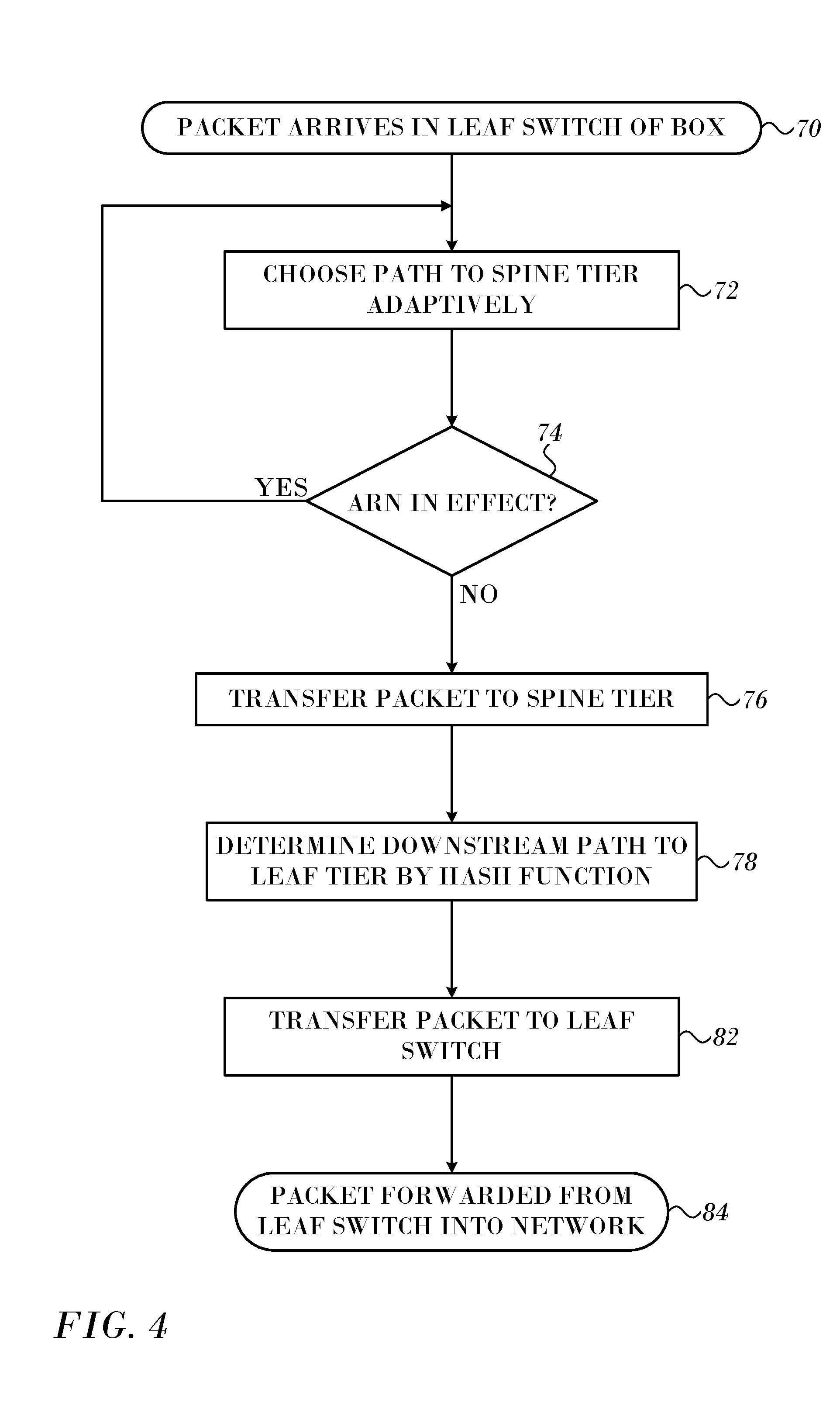
[0022] FIG. 4 is a flow chart of a method of operating a network box in accordance with an embodiment of the invention; and
[0023] FIG. 5 is a schematic diagram of a switch with radix 16, in accordance with an alternate embodiment of the invention.
DETAILED DESCRIPTION OF THE INVENTION
[0024] In the following description, numerous specific details are set forth in order to provide a thorough understanding of the various principles of the present invention. It will be apparent to one skilled in the art, however, that not all these details are necessarily always needed for practicing the present invention. In this instance, well-known circuits, control logic, and the details of computer program instructions for conventional algorithms and processes have not been shown in detail in order not to obscure the general concepts unnecessarily.
[0025] Documents incorporated by reference herein are to be considered an integral part of the application except that, to the extent that any terms are defined in these incorporated documents in a manner that conflicts with definitions made explicitly or implicitly in the present specification, only the definitions in the present specification should be considered.
[0026] According to RFC 6437, and as used herein, a flow (or data flow) is a sequence of packets sent from a particular source to a particular unicast, anycast, or multicast destination that the source desires to label as a flow. A flow could consist of all packets in a specific transport connection or a media stream.
[0027] Turning now to the drawings, reference is now made to FIG. 1, which is a block diagram of a typical network element 10, which can be used as a switch in a box in accordance with an embodiment of the invention. It can be configured with multiple ports 12 connected to a packet communication network. A processor 11, comprising any number of cores 13, is linked to decision logic 14. The decision logic 14 applies classification rules in forwarding data packets 16 between ports 12, as well as performing other actions, such as encapsulation and decapsulation, security filtering, and/or quality-of-service functions. The circuitry needed for carrying out such forwarding and other functions will be apparent to those skilled in the art and is omitted from the figures for the sake of simplicity, in order to concentrate on the actual classification functions of decision logic 14.
[0028] In the pictured embodiment, decision logic 14 receives packets 16, each containing a header 18 and payload data 20. A processing pipeline 22 in decision logic 14 extracts a classification key from each packet, typically (although not necessarily) including the contents of certain fields of header 18. For example, the key may comprise the source and destination addresses and ports and a protocol identifier. Pipeline 22 matches the key against a matching database 24 containing a set of rule entries, which is stored in an SRAM 26 in network element 10, as described in detail hereinbelow. SRAM 26 also contains a list of actions 28 to be performed when a key is found to match one of the rule entries and may include a forwarding database. For this purpose, each rule entry typically contains a pointer to the particular action that decision logic 14 is to apply to packets 16 in case of a match. Pipeline 22 typically comprises dedicated or programmable hardware logic, which is configured to carry out the functions described herein.
[0029] Reference is now made to FIG. 2, which is a schematic diagram of a box 40 with radix 16, comprising a matrix of several switches, all with radix 8, in accordance with an embodiment of the invention. The switches can be separate integrated circuits, or all of them can be fabricated as a single integrated circuit. In embodiments of the invention, each of the switches include instances of the processor 11 and decision logic 14 (FIG. 1). Box 40 comprises a leaf tier 42 of four leaf switches 44, 46, 48, 50 that exchange data with a data network via network ports (port numbers 0-3) and with a spine tier 52 of spine switches 54, 56 (port numbers 4-7). While a 2:1 ratio of leaf to spine switches is shown in the switch network of the box 40, other arrangement are possible, and the box may be composed of switch elements having other radices, so long as the radix of the box exceeds the radix of other switches in the network. Typically the switches in the box 40 are realized as ASICs. Boxes of this sort can be constructed to create network switches with higher radices, for example by increasing the number or the radix of the leaf and spine switches in many combinations. The principles of the invention can be applied, mutatis mutandis, to all such combinations. A processor 57 synchronizes the switches, as described below. Boxes with three or more tiers can be also be constructed.
[0030] Each spine switch is connected to each leaf switch by at least one link between ports. Many combinations of links are possible, depending on the configuration of the switches in the box. In the example of FIG. 2, pairs of ports in each of the spine switches 54, 56 are connected to respective pairs of ports in each of the leaf switches 44, 46, 48, 50. Some connections are omitted for clarity. For example, in the leaf switch 44 ports numbers 6, 7 connect with ports numbers 6, 7 of spine switch 54, and port numbers 4, 5 connect with port numbers 6, 7 of spine switch 56. In another example, in a box of radix 8 switches having eight leaf switches and four spine switches, a port of each spine switch could be connected with a single port of each leaf switch, rather than by a pair of ports as shown in FIG. 2.
[0031] In FIG. 2, the network ports (port numbers 0-3) of leaf switches 44, 46 are uplinks, while the network ports of the leaf switches 48, 50 are downlinks. This assignment is exemplary, and other combinations of port assignments to uplink and downlink roles are possible in order to support a particular network topology. The box 40 in the example of FIG. 2 is adapted for use as a single switch in a clos (fat tree) network topology, which is a common network topology that advantageously employs switches provided by boxes of this sort.
[0032] Switch elements in a fat tree topology can be either single switches or boxes. Each such box constitutes a switch with a higher radix than the single switches. Reference is now made to FIG. 3, which is a three-level fat tree network 58, in accordance with an embodiment of the invention. The network 58 includes an upper tier 60, middle tier 62 and lower tier 64. The middle tier 62 includes six switch elements (labeled B0-B1, B2-B3, B4, B5, B6 and B7) The switch element B0-B1 is realized as the box 40. Switch elements B4-B7 have radix 8. Box 40 (switch element B0-B1) has radix 16, as noted above in the discussion of FIG. 1, and replaces two switches with radix 8. Representative uplink connections 66 and downlink connections 68 from box 40 to upper tier 60 and lower tier 64, are shown. Although not shown in detail, switch element B2-B3 may also be replaced by an instance of the box 40.
[0033] Configuring and operating a high radix switch of the sort illustrated by the box 40 presents performance issues, resulting in part from the need for data to traverse more than one tier of switches within the box. Referring again to FIG. 2, each packet of data passes through the box 40 through ingress ports of the leaf switches 44, 46, 48, 50, transiting selected spine switches 54, 56 and then exiting via exit ports of the leaf switches.
[0034] In order to guarantee that packets belonging to the same flow exit the box 40 through the same egress port, the switches in the spine tier 52 are synchronized. The spine switches use the same hash function and perform the hash on the same packet fields. Otherwise, if, for example, one of the spine switches were to be updated so as to modify the size of its ECMP groups, the distribution of flow into ports could change, causing a single flow to exit from multiple egress ports of the leaf switches.
[0035] Moreover, where there is a change in the routing protocol, such as the border gateway protocol (BGP), all of the spine switches begin to use the updated routing data at the same time. This is achieved by managing the protocol in the synchronization processor 57 (FIG. 2) that is configured to push updates to all the spine switches. Time synchronization among the spine switches assures that the changeover to the updated routing data occurs at the same time.
[0036] Reference is now made to FIG. 4, which is a flow chart of a method of operating a network box in accordance with an embodiment of the invention. The method is explained with regard to one packet and the exemplary network 58 (FIG. 3). However it will be understood that the box may receive multiple packets asynchronously in different ingress ports, all of which are processed in like manner. Moreover, the process steps are shown in a particular linear sequence in FIG. 4 for clarity of presentation. However, it will be evident that many of them can be performed in parallel, asynchronously, or in different orders. Those skilled in the art will also appreciate that a process could alternatively be represented as a number of interrelated states or events, e.g., in a state diagram. Moreover, not all illustrated process steps may be required to implement the method.
[0037] At initial step 70 a packet is transmitted to the middle tier 62, arriving from the lower tier 64 or from the upper tier 60. In either case the packet arrives at an ingress port of one of the leaf switches 44, 46, 48, 50 in the box 40 and will eventually leave the box 40 via an egress port;
[0038] The arriving packet is processed initially at step 72. In order to eventually reach an egress port, the packet must first pass from the ingress leaf switch through one of the spine switches 54, 56 and thence to one of the leaf switches 44, 46, 48, 50. The box 40 constitutes a multi-path routing system.
[0039] At step 72 one of the paths to the spine tier 52 is chosen according to a governing adaptive routing algorithm. The path ends at a selected port of a chosen spine switch. Many adaptive routing algorithms can be implemented in step 72 and in other steps of FIG. 2 that involve adaptive routing. One example is the ECMP algorithm, which balances multiple flows over multiple paths by hashing traffic flows onto multiple best paths. However, some variants of the ECMP-based load balancing algorithm do not consider traffic load and may not steer traffic away from congested links. Other adaptive routing methods vary routing based on identified congestion. Two examples are found in commonly assigned U.S. Patent Application Publication Nos. 2017/0244630 by Levy et al., and 2014/0211631 by Haramaty et al., which are herein incorporated by reference, and which can be applied to step 72, mutatis mutandis. These algorithms generally offer tradeoffs between collision avoidance, congestion, and load balancing. Detailed consideration of the tradeoffs in the selection of an adaptive routing algorithm is outside the scope of this disclosure.
[0040] Embodiments of the invention signal switch congestion by issuing notifications to a preceding switch on a chosen path. At decision step 74 it is determined if an Adaptive Routing Notification (ARN) is in effect. In some embodiments the ARN may apply to all packets being sent to the port of the spine switch selected in step 72. Alternatively, an ARN may constitute a congestion indication for a particular flow and could be ignored for packets not belonging to that flow. The algorithm chosen in step 72 and the issuance of an ARN take into consideration both congestion on the egress ports of the leaf switch (local congestion) and congestion on the egress ports of the spine switch (remote congestion). In current embodiments, when a packet of a flow is transmitted from a leaf switch to a spine switch and encounters congestion in the spine switch, the spine switch transmits an ARN to that leaf switch as a reaction to the congestion. The leaf switch is then forced to reroute packets of the flow to an alternative spine switch, even in the absence of local congestion in the leaf switch. However the selection of the alternative spine switch may take both local congestion and the ARN into account. ARNs are described in further detail in the above-noted Levy et al. and Haramaty et al. disclosures.
[0041] If an ARN is in effect at decision step 74, then the chosen port is avoided, and control returns to step 72 to iterate the path selection.
[0042] If there is no ARN in effect, the packet is transferred to the selected port of the spine switch at step 76.
[0043] Traffic moving upstream in a fat tree network outside the box 40 is usually multi-path and it is not essential that packets of a given flow exit the box through the same port. Thus, there is flexibility in the choice of a spine-to-leaf path within the box 40. For such traffic dynamic load balancing techniques may be employed in spine-to-leaf routing within the box 40.
[0044] Nevertheless, when processing such upstream traffic inside the box 40 the spine-to-leaf routing in the segment that terminates at one of the leaf switches 44, 46, 48, 50 is established statically to ensure that for a given flow, all such packets exit the box 40 through the same port. For example, in a box having three tiers of switches, only the path from the middle tier to the leaf switches need be statically established.
[0045] Traffic moving downstream in a fat tree network outside the box 40 is usually single path traffic. When processing such downstream traffic inside the box 40 the spine-to-leaf routing in the segment that terminates at one of the leaf switches 44, 46, 48, 50 has only a single path choice.
[0046] Leaf-to-spine traffic within box 40 is always dynamically load-balanced, irrespective of the direction of the traffic in the fat tree network outside of the box 40.
[0047] In some embodiments hash-based forwarding is used in step 78. The forwarding algorithm may select an egress port number of a leaf switch as described in commonly assigned U.S. Patent Application Publication No. 2017/0187614 by Haramaty et al., which is herein incorporated by reference. The hashing techniques described in commonly assigned U.S. Patent Application Publication Nos. 20170286292, 20170270119 and 20170068669, all of which are herein incorporated by reference, may be used in step 78, mutatis mutandis.
[0048] Then at step 82 the packet is transferred to a designated port of a leaf switch.
[0049] At final step 84 the packet is forwarded into the network from the egress port of the designated leaf switch. Typically the egress port of the leaf switch is determined from routing information in the packet.
[0050] The above described algorithm achieves selective load balancing within the box, i.e., on upstream paths. In downstream paths within the box 40, load balancing is sacrificed for consistency in packet egress. In some applications it is desired that all packets belonging to the same flow exit the network box through the same egress port in order to control and debug a network, recognizing that this constraint may result in packets of a flow exiting the box out of order.
Alternate Embodiments
[0051] Reference is now made to FIG. 5, which is a schematic diagram of a box 86 with radix 16, comprising a matrix of spine switches 88 and leaf switches 90, all with radix 8, in accordance with an alternate embodiment of the invention. The spine switches 88 and leaf switches 90 are connected and function in the same manner as the switches in the box 40 (FIG. 2). However, there is a management decision processor 92 connected to all of the switches in the box 86. The management decision processor 92 is provided with decision logic, which carries out the functions of the processor 11 and decision logic 14 (FIG. 1) for all of the switches, as well as the synchronization functions noted above. This arrangement reduces the hardware in the box 86 compared with the box 40, with corresponding economies in power usage. Separate instances of the processor 11 and decision logic 14 may be omitted or economically modified.
[0052] It will be appreciated by persons skilled in the art that the present invention is not limited to what has been particularly shown and described hereinabove. Rather, the scope of the present invention includes both combinations and sub-combinations of the various features described hereinabove, as well as variations and modifications thereof that are not in the prior art, which would occur to persons skilled in the art upon reading the foregoing description.
* * * * *
D00000
D00001
D00002
D00003
D00004
D00005
XML
uspto.report is an independent third-party trademark research tool that is not affiliated, endorsed, or sponsored by the United States Patent and Trademark Office (USPTO) or any other governmental organization. The information provided by uspto.report is based on publicly available data at the time of writing and is intended for informational purposes only.
While we strive to provide accurate and up-to-date information, we do not guarantee the accuracy, completeness, reliability, or suitability of the information displayed on this site. The use of this site is at your own risk. Any reliance you place on such information is therefore strictly at your own risk.
All official trademark data, including owner information, should be verified by visiting the official USPTO website at www.uspto.gov. This site is not intended to replace professional legal advice and should not be used as a substitute for consulting with a legal professional who is knowledgeable about trademark law.