Forward Packet Recovery With Constrained Network Overhead
Hughes; David Anthony
U.S. patent application number 16/396467 was filed with the patent office on 2019-08-15 for forward packet recovery with constrained network overhead. The applicant listed for this patent is Silver Peak Systems, Inc.. Invention is credited to David Anthony Hughes.
| Application Number | 20190253187 16/396467 |
| Document ID | / |
| Family ID | 62045162 |
| Filed Date | 2019-08-15 |


View All Diagrams
| United States Patent Application | 20190253187 |
| Kind Code | A1 |
| Hughes; David Anthony | August 15, 2019 |
FORWARD PACKET RECOVERY WITH CONSTRAINED NETWORK OVERHEAD
Abstract
Disclosed herein are systems and methods for forward packet recovery in a communication network with constrained network bandwidth overhead. In exemplary embodiments, a target byte protection ratio is determined. Error correcting frames are dynamically generated by a first processor such that error correcting information can be generated to approximate the target byte protection ratio. The data packets and error correcting information are then transmitted across one or more communication networks to a second processor. The second processor can use the error correcting information to regenerate or replace data packets missing or corrupted in transmission across one or more communication networks.
| Inventors: | Hughes; David Anthony; (Los Altos Hills, CA) | ||||||||||
| Applicant: |
|
||||||||||
|---|---|---|---|---|---|---|---|---|---|---|---|
| Family ID: | 62045162 | ||||||||||
| Appl. No.: | 16/396467 | ||||||||||
| Filed: | April 26, 2019 |
Related U.S. Patent Documents
| Application Number | Filing Date | Patent Number | ||
|---|---|---|---|---|
| 15918807 | Mar 12, 2018 | 10326551 | ||
| 16396467 | ||||
| 15241992 | Aug 19, 2016 | 9967056 | ||
| 15918807 | ||||
| Current U.S. Class: | 1/1 |
| Current CPC Class: | H04L 1/0083 20130101; H04L 1/0086 20130101; H04L 1/0007 20130101; H04L 69/22 20130101; H04L 1/0041 20130101; H04L 1/0057 20130101 |
| International Class: | H04L 1/00 20060101 H04L001/00; H04L 29/06 20060101 H04L029/06 |
Claims
1. A computer-implemented method for providing corrected data packets to a second processor, the method comprising: receiving at a first processor, a data stream comprising a plurality of data packets for transmission across at least one communication network, the plurality of data packets being of various sizes; selecting a target byte protection ratio for the data stream, the target byte protection ratio representing a target number of bytes of error correcting information per bytes of data in the data stream; categorizing the plurality of data packets in the data stream into a plurality of categories according to size, the categories comprising data packets of a first size range and data packets of a second size range, wherein the second size range is larger than the first size range; generating one or more error correcting frames for each category of the plurality of categories, such that each error correcting frame comprises data packets of a comparable size; generating one or more error correction data packets for each error correcting frame, in accordance with the target byte protection ratio; and transmitting the plurality of data packets and the one or more error correction data packets across the at least one communication network to the second processor.
2. The method of claim 1, wherein the target byte protection ratio for the data stream is selected to correspond to a target network bandwidth usage for the error correcting information.
3. The method of claim 1, wherein the one or more error correcting frames are further generated in accordance with a timeout policy, such that all packets received within a certain period of time are determined to be within the one or more error correcting frames.
4. The method of claim 1, wherein the generating one or more error correcting frames for each category further comprises generating one or more error correcting frames of information for corresponding data packets, such that the error correcting information for the data stream is in a different order than the data packets of the data stream.
5. The method of claim 1, wherein the transmitting the plurality of data packets comprises transmitting the data packets from the data stream in order of receipt, and the transmitting the one or more error correction data packets comprises transmitting error correction information out of order from the order of corresponding data packets in the data stream.
6. The method of claim 1, wherein the generating one or more error correction data packets in accordance with the target byte protection ratio further comprises: keeping a running tally of a number of error correction data packets generated for all error correcting frames in the data stream; and adjusting an amount of error correction data packets generated for each subsequent frame based on the running tally of error correction data packets for the data stream, in accordance with the target byte protection ratio for the data stream.
7. The method of claim 1, wherein the receiving the plurality of data packets for transmission across the at least one communication network further comprises: comparing a size of each data packet to a maximum transmission unit capacity of the at least one communication network; and fragmenting each data packet above the capacity of the maximum transmission unit for the at least one communication network into two or more portions of substantially equal size.
8. The method of claim 1, wherein the generating one or more error correcting frames for the data stream further comprises: segmenting the data packets of the second size range into a first portion equivalent in size to at least one of the data packets of the first size range and a second portion comprising a remainder of the data packet of the second size range; generating at least one error correcting frame for the data packets of the first size range and the first portion of the data packets of the second size range; and generating at least one error correcting frame for the second portion of the data packets of the second size range.
9. The method of claim 1, wherein at least one of the plurality of data packets is received out of order at the second processor.
10. The method of claim 1, wherein error correcting information in at least one error correction data packet is generated using Reed-Solomon coding.
11. The method of claim 1, further comprising regenerating the data stream at the second processor by: receiving the plurality of data packets and the one or more error correction data packets from the first processor; and utilizing information in the received plurality of data packets and the received one or more error correction data packets to regenerate the data stream by correcting at least one lost, corrupt, or out of order data packet in the data stream.
12. The method of claim 1, further comprising regenerating the data stream at the second processor by: receiving the plurality of data packets and the one or more error correction data packets from the first processor; and utilizing a sequence number in a header of the received plurality of data packets and the received one or more error correction data packets to regenerate the data stream by correcting at least one lost, corrupt, or out of order data packet in the data stream.
13. A computer-implemented method for regenerating a data stream received at a second processor from a first processor across at least one communication network; the method comprising: receiving a plurality of data packets and one or more error correction data packets from the first processor; wherein the one or more error correction data packets are generated by the first processor in accordance with a target byte protection ratio for the data stream, the target byte protection ratio representing a target number of bytes of error correcting information per bytes of data in the data stream; and utilizing the received plurality of data packets and the received one or more error correction data packets to regenerate the data stream by correcting at least one lost, corrupt, or out of order data packet in the data stream.
14. The method of claim 13, wherein the one or more error correction data packets are generated from one or more generated error correcting frames, each error correcting frame comprising data packets of a comparable size.
15. The method of claim 13, wherein the one or more error correction data packets are generated by the first processor with error correction information for the data stream that is in a different order than the data packets of the data stream.
16. The method of claim 13, wherein the target byte protection ratio for the data stream is selected to correspond to a target network bandwidth usage for the error correcting information.
17. A computing system for providing corrected data packets to a second network appliance, the system comprising: a first network appliance in communication with a second network appliance via at least one communication network, the first network appliance comprising at least one processor configured to: receive a data stream comprising a plurality of data packets for transmission across the at least one communication network to the second network appliance; select a target byte protection ratio for the data stream, the target byte protection ratio representing a target number of bytes of error correcting information per bytes of data in the data stream; categorize the plurality of data packets in the data stream according to size, the categories comprising a first category of data packets within a first size range and a second category of data packets within a second size range; generate one or more error correcting frames for each category, such that each error correcting frame comprises data packets of a comparable size; generate one or more error correction data packets for each dynamically generated error correcting frame, in accordance with the target byte protection ratio; and transmit the plurality of data packets and the one or more error correction data packets across the at least one communication network to the second network appliance.
18. The system of claim 17, wherein the second network appliance comprises at least one processor configured to: receive the plurality of data packets and the one or more error correction data packets from the first network appliance; and utilize the received plurality of data packets and the received one or more error correction data packets to regenerate the data stream in order by correcting at least one lost, corrupt, or out of order data packet in the data stream.
19. The system of claim 17, wherein the target byte protection ratio for the data stream is selected to correspond to a target network bandwidth usage for the error correcting information.
20. The system of claim 17, wherein the generating one or more error correcting frames for each category further comprises generating one or more error correcting frames of information for corresponding data packets, such that the error correcting information for the data stream is in a different order than the data packets of the data stream.
Description
CROSS-REFERENCE TO RELATED APPLICATIONS
[0001] The present patent application is a Continuation of, and claims the priority benefit of, U.S. patent application Ser. No. 15/918,807 filed on Mar. 12, 2018 and entitled "Forward Packet Recovery with Constrained Network Overhead", which in turn is a Divisional Application of, and claims the priority benefit of, U.S. patent application Ser. No. 15/241,992 filed on Aug. 19, 2016 and entitled "Forward Packet Recovery with Constrained Overhead", now granted as U.S. Pat. No. 9,967,056 issued on May 8, 2018. The disclosures of the above-referenced applications are hereby incorporated by reference in their entirety for all purposes.
TECHNICAL FIELD
[0002] This disclosure relates generally to network communications and more specifically to forward packet recovery.
BACKGROUND
[0003] The approaches described in this section could be pursued, but are not necessarily approaches that have previously been conceived or pursued. Therefore, unless otherwise indicated, it should not be assumed that any of the approaches described in this section qualify as prior art merely by virtue of their inclusion in this section.
[0004] Typically, data is sent between computing devices across a communications network in packets. The packets may be generated according to a variety of protocols such as Transmission Control Protocol (TCP), User Datagram Protocol (UDP), or the like. During transmission, packets may be lost, corrupted, or received out of order. In these instances, the computing device sending the packets may have to resend the packets or the receiving application may have methods for coping with missing or corrupted packets. Either way the impairments are undesirable.
[0005] Forward packet recovery methods provide for generating and transmitting additional parity packets across a communications network. The parity packet contains information that can be used to reconstruct or replace one or more corrupted or lost packets at the receiver side. Parity packets are traditionally sent in a ratio based on a number of data packets transmitted. For example, one parity packet may be sent per five data packets. However, since the number and amount of parity information is based on a number of data packets transmitted, the amount of network bandwidth needed for transmission of these packets is unpredictable, at least because data packets can be of varying sizes.
[0006] Thus, there is a need for a mechanism for transmitting error correcting information to repair or replace data based on a number of bytes transmitted, rather than based on a number of packets transmitted across one or more communication networks, to accommodate for constrained network resources.
SUMMARY
[0007] This summary is provided to introduce a selection of concepts in a simplified form that are further described in the Detailed Description below. This summary is not intended to identify key features or essential features of the claimed subject matter, nor is it intended to be used as an aid in determining the scope of the claimed subject matter.
[0008] In various exemplary methods of the present disclosure, a first processor receives a data stream comprising a plurality of data packets for transmission across at least one communication network, selects a target byte protection ratio for the data transmission, the target byte protection ratio representing a target number of bytes of error correcting information per bytes of data in the data stream, dynamically generates one or more error correcting frames for the data stream, generates one or more error correction data packets for each error correcting frame of data in accordance with the target byte protection ratio, and transmits the plurality of data packets and the one or more error correction data packets across the at least one communication network to a second processor.
[0009] The error correcting frames can be dynamically generated by grouping data packets of the data stream in various configurations, fragmenting data packets, and/or segmenting data packets. By adjusting the error correcting frames in this way, the amount of error correcting information generated in accordance with the target byte protection ratio is reduced in comparison to a target packet protection ratio. Further, error correction information is generated in accordance with constrained network overhead resource requirements.
[0010] Other features, examples, and embodiments are described below.
BRIEF DESCRIPTION OF THE DRAWINGS
[0011] Embodiments are illustrated by way of example and not by limitation in the figures of the accompanying drawings, in which like references indicate similar elements.
[0012] FIG. 1 is a diagram of an exemplary environment in which various embodiments of the present disclosure may be practiced.
[0013] FIG. 2 is an exemplary schematic of a network appliance.
[0014] FIG. 3 depicts an exemplary error correcting frame of prior systems.
[0015] FIG. 4A depicts an exemplary embodiment of dynamic framing via grouping of data packets.
[0016] FIG. 4B depicts an exemplary flow sequence for a data protector to determine a number of error correction packets to generate for each frame.
[0017] FIG. 5A depicts an exemplary embodiment of fragmenting data packets in prior systems.
[0018] FIG. 5B depicts an exemplary embodiment of dynamic framing via fragmenting data packets.
[0019] FIG. 6 depicts an exemplary embodiment of dynamic framing via interleaving data packets.
[0020] FIG. 7 depicts an exemplary embodiment of dynamic framing via splitting data packets.
[0021] FIG. 8 depicts an exemplary embodiment of generating byte based error correction information for a plurality of data packets using a data structure.
[0022] FIG. 9A depicts another exemplary embodiment of generating byte based error correction information for a plurality of data packets using a data structure.
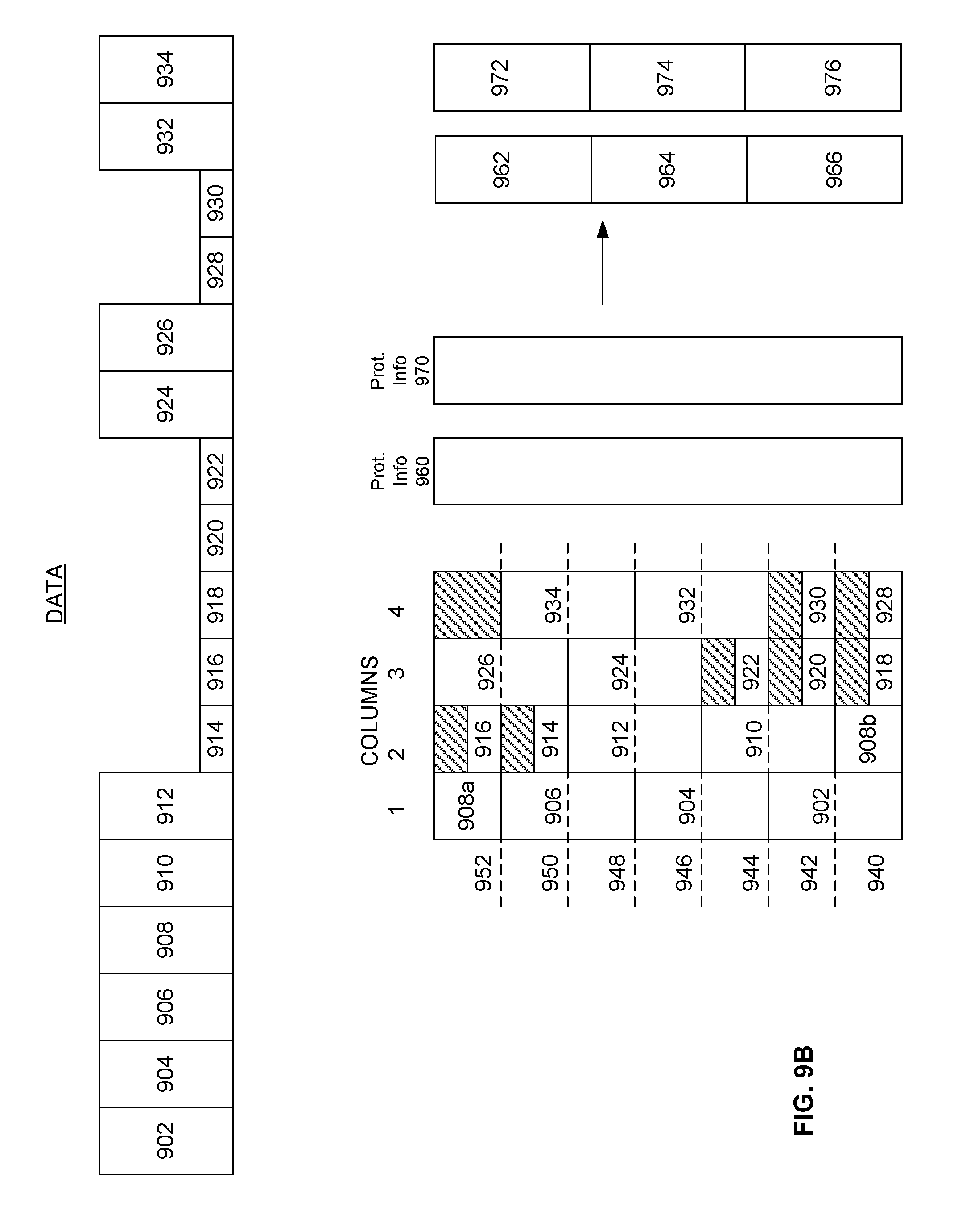
[0023] FIG. 9B depicts a further exemplary embodiment of generating byte based error correction information for a plurality of data packets using a data structure.
DETAILED DESCRIPTION
[0024] The following detailed description includes references to the accompanying drawings, which form a part of the detailed description. The drawings show illustrations, in accordance with exemplary embodiments. These exemplary embodiments, which are also referred to herein as "examples," are described in enough detail to enable those skilled in the art to practice the present subject matter. The embodiments can be combined, other embodiments can be utilized, or structural, logical, and electrical changes can be made without departing from the scope of what is claimed. The following detailed description is therefore not to be taken in a limiting sense, and the scope is defined by the appended claims and their equivalents. In this document, the terms "a" and "an" are used, as is common in patent documents, to include one or more than one. In this document, the term "or" is used to refer to a nonexclusive "or," such that "A or B" includes "A but not B," "B but not A," and "A and B," unless otherwise indicated.
[0025] The embodiments disclosed herein may be implemented using a variety of technologies. For example, the methods described herein may be implemented in software executing on a computer system containing one or more computers, or in hardware utilizing either a combination of microprocessors or other specially designed application-specific integrated circuits (ASICs), programmable logic devices, or various combinations thereof. In particular, the methods described herein may be implemented by a series of computer-executable instructions residing on a storage medium, such as a disk drive, or computer-readable medium.
[0026] The embodiments described herein relate to forward packet recovery for data transmitted across one or more communication networks.
[0027] Exemplary systems and methods for forward packet recovery are provided. Forward packet recovery can be used to reconstruct missing data packets and corrupted data packets and order the received and reconstructed data packets prior to processing according to a protocol such as Transmission Control Protocol (TCP), User Datagram Protocol (UDP), or the like. In order to perform forward packet recovery, protection packets with error correcting information are sent with the data packets. Protection packets are also sometimes referred to herein as correction packets, error correction packets, error correction data packets or protection data packets. Typically, one protection packet can be used to reconstruct one missing or corrupted data packet. However, sending the protection packets in addition to the data packets uses more bandwidth in a communication network which may, in turn, slow communications between network appliances. However, not sending a sufficient number of protection packets may result in having to resend data packets. Missing data packets and out of order packets can negatively impact performance of TCP and other high level protocols.
[0028] Protection packets can be sent based on data packets in an error correcting frame of a stream of data. As used herein, a stream of data can be any sequence of data packets transmitted between two devices. A stream may be the same as a flow, as understood by persons of ordinary skill in the art, or may be different than a flow. A stream can be comprised of an aggregate of multiple flows or sessions. The stream may contain packets using TCP, UDP, and/or other protocols. In some implementations separate streams may be created for different quality of service classes or types of traffic.
[0029] FIG. 1 is a diagram of an environment 100 in which various embodiments of the present disclosure may be practiced. The environment 100 comprises a network appliance A 102 and a network appliance B 104 communicatively coupled via one or more communication network(s) 106. While two network appliances are depicted in FIG. 1 for exemplary purposes, there can be any number of network appliances communicatively coupled to one or more other network appliances.
[0030] In a wide area network, there can be multiple network appliances deployed in one or more geographic locations. Each network appliance comprises hardware and/or software elements configured to receive data and optionally perform any type of processing, including but not limited to, WAN optimization techniques to the data, before transmitting to another appliance or an endpoint device. In various embodiments, a network appliance can be configured as an additional router or gateway. If a network appliance has multiple interfaces, it can be transparent on some interfaces, act like a router on some interfaces, or be a bridge on others. Alternatively, the network appliance can be transparent on all interfaces, or appear as a router, or appear as a bridge on all interfaces. In some embodiments, network traffic can be intercepted by another device and mirrored (copied) onto a network appliance. Each network appliance may further be either physical or virtual. For example, a virtual network appliance can be in a private data center or virtual private cloud (not shown), managed by a cloud service provider, such as Amazon Web Services, or others.
[0031] The communication network(s) 106 may comprise a Wide Area Network (WAN), the Internet, MPLS (Multiprotocol Label Switching), LTE (Long Term Evolution), or any other wired or wireless network, as will be apparent to those skilled in the art. The network appliance A 102 and the network appliance B 104 may be communicatively coupled via one or more communication network(s) 106, including any combination of WAN, Internet, MPLS, or LTE. In various embodiments, network appliance A 102 and network appliance B 104 communicate via at least two communication networks.
[0032] In various embodiments, network appliance A 102 and network appliance B 104 are optionally in communication with endpoint devices 108 and 126, respectively. The network appliances can be optionally in communication with the endpoint devices either directly or through other intermediate devices such as switches and routers (not shown). Endpoint devices 108 and 126 may each comprise a computer, a server, a mobile device, or the like as will be apparent to those skilled in the art. Endpoint devices 108 and 126 may or may not be communicatively coupled directly to one or more communication network(s) 106 in addition to, or instead of, through a network appliance.
[0033] In the exemplary depiction in FIG. 1, network appliance A 102 is configured to send data packets to network appliance B 104 via one or more communication network(s) 106. Network appliance B 104 is configured to receive data packets from network appliance A 102. In other embodiments, network appliance B 104 may transmit data and network appliance A 102 may receive data. Each network appliance can comprise a computer, a server, a router, or the like. A network appliance is described further herein with respect to FIG. 2.
[0034] The network appliance A 102 comprises sub-systems that perform certain functions. In various embodiments, network appliance A 102 comprises at least an internal source 109, a pre-processor 110, data protector 112, and a transmitter 114. Certain functions of one or more sub-systems may be combined, or performed by additional sub-systems.
[0035] In an exemplary embodiment, network appliance A 102 has data to be transmitted across one or more communication network(s) 106 to network appliance B 104 or to endpoint device 126 in communication with network appliance B 104. The data for transmission may be received by network appliance A 102 from endpoint device 108, or may be generated by internal source 109 of network appliance A 102 itself.
[0036] In various embodiments, pre-processor 110 is a hardware and/or software component of network appliance A 102. The pre-processor 110 may receive data for transmission from endpoint device 108, receive data internally generated from another sub-system of network appliance A 102, or generate the data itself. Pre-processor 110 may also optionally perform other operations on the data, such as formatting, encapsulating, coalescing, or optimizing. Optimization techniques performed to the data can include such items as compression, encryption, and adding tunnel headers. While only a few examples are listed here, a person of ordinary skill in the art would understand that pre-processor 110 can perform any data optimization technique on the data.
[0037] Data protector 112 is a hardware and/or software component of network appliance A 102. In various embodiments, data protector 112 is configured to generate protection packets based on data packets received from the pre-processor 110 and a protection ratio. Protection may be used by, for example, the network appliance B 104 to reconstruct data packets that are corrupted or missing. A packet protection ratio indicates the number of protection packets per the number of data packets, and a byte protection ratio indicates the number of correction bytes per the number of data bytes in the data frame (also referred to herein as error correcting frame, or simply frame).
[0038] In some systems, one or more protection packets are sent with each frame. The protection packet may be a byte-wise exclusive-or (XOR) of all of the data packets in the frame. As is known to those skilled in the art, any single missing or corrupted data packet can be recovered using an XOR operation. Although the XOR operation is discussed, there are many ways one or more missing or corrupted data packets can be recovered, depending on the protection algorithm. The error correction packet is often referred to as a parity packet. While XOR is often used to generate parity packets, there are other methods for generating other types of protection packets (also sometimes referred to herein as protection data or protection information) which may use other operations.
[0039] In various embodiments, data protector 112 is configured to generate more than one protection packet per a defined number of data packets. For example, the packet protection ratio may be 8:40 indicating that, for a frame comprising forty data packets, eight distinct protection packets are additionally generated. This may be performed using a unique, identifiable function to generate each of the protection packets. Using a ratio of 8:40 rather than a ratio of 1:5 allows for more missing or corrupted packets that are, for example, sequential to one another, to be reconstructed and thus avoids resending multiple packets. The more than one protection packets may be generated based on algorithms using Reed-Solomon coding and finite field arithmetic, as is known to those skilled in the art, or other methods.
[0040] Further, in some embodiments, the data protector 112 is configured to change the protection ratio dynamically. This may be in response to network measurements, for example increasing the ratio when the observed loss is low and decreasing the ratio which the observed loss is high. In some circumstances the ratio will be changed when the framing algorithm "times out" because the stream has no packets to send.
[0041] Transmitter 114 is a hardware and/or software component of network appliance A 102. In various embodiments, transmitter 114 is configured to queue and transmit data packets and protection packets across one or more communication network(s) 106 to network appliance B 104. Protection packets may be transmitted substantially simultaneously as data packets, or may be sent at a delay or upon the meeting of a condition. Exemplary conditions include a frame boundary, a network condition, or a timeout parameter being met. In various embodiments, transmitter 114 can send data across multiple networks of the one or more communication network(s) 106 simultaneously, or in an alternating, interleaving or interspersed manner.
[0042] The network appliance B 104 comprises sub-systems that perform certain functions. In various embodiments, network appliance B 104 comprises at least, a receiver 116, a data corrector 118, a post-processor 122, an internal destination 124, and optionally an ordering sub-system 120. The network appliance B 104 may additionally be configured as a network appliance A 102 and may be a computer, server, router, network appliance, or the like.
[0043] Receiver 116 is a hardware and/or software component of network appliance B 104. The receiver 116 is configured to receive data packets and protection packets from the network appliance A 102 via one or more communication network(s) 106.
[0044] Data corrector 118 is a hardware and/or software component of network appliance B 104. Data corrector 118 is configured to determine if any data packets are missing, corrupted, or out of order. If any data packets are missing or corrupted, data corrector 118 is configured to determine whether the missing or corrupted packets can be reconstructed using a combination of the correctly received data packets and the received protection packets and, if the packets can be reconstructed, reconstruct the packets.
[0045] When present, the ordering sub-system 120 is configured to order the received packets, or copies of the received packets, and the reconstructed packets prior to processing by the post-processor 122. Ordering may be based on a sequence number in the header information of each packet. Ordering sub-system 120 is a hardware and/or software component of network appliance B 104. In exemplary embodiments where network appliance B 104 does not include an ordering sub-system 120, data packets may be re-ordered by endpoint device 126 or another recipient of the data. In some embodiments, the network appliance B 104 is configured to copy incoming packets, to send one copy to the data corrector 118, and send the other copy to the ordering sub-system 120.
[0046] Post-processor 122 is configured to receive data packets and reconstructed data packets from data corrector 118 and/or ordering sub-system 120, and deliver the data to endpoint device 126 or to an internal destination 124 of network appliance B 104. Post-processor 122 is a hardware and/or software component of network appliance B 104 that often performs an inverse operation to pre-processor 110 (decrypt, decompress, etc.).
[0047] FIG. 2 illustrates a block diagram of a network appliance 202, in an exemplary implementation of the disclosure. Network appliance 202 can be configured as network appliance A 102 or network appliance B 104 of FIG. 1. The network appliance 202 includes a processor 210, a memory 220, a WAN communication interface 230, a LAN communication interface 240, and a database 250. A system bus 280 links the processor 210, the memory 220, the WAN communication interface 230, the LAN communication interface 240, and the database 250. Line 260 links the WAN communication interface 230 to another device, such as another appliance, router, or gateway, and line 270 links the LAN communication interface 240 to a user computing device, or other networking device. While network appliance 202 is depicted in FIG. 2 as having these exemplary components, the appliance may have additional or fewer components.
[0048] The database 250 comprises hardware and/or software elements configured to store data in an organized format to allow the processor 210 to create, modify, and retrieve the data. The hardware and/or software elements of the database 250 may include storage devices, such as RAM, hard drives, optical drives, flash memory, and magnetic tape.
[0049] In some embodiments, some network appliances comprise identical hardware and/or software elements. Alternatively, in other embodiments, some network appliances may include hardware and/or software elements providing additional processing, communication, and storage capacity.
[0050] Each network appliance 202 can be in communication with at least one other network appliance 202, whether in the same geographic location, different geographic location, private cloud network, customer datacenter, or any other location. As understood by persons of ordinary skill in the art, any type of network topology may be used. There can be one or more secure tunnels between one or more network appliances. The secure tunnel may be utilized with encryption (e.g., IPsec), access control lists (ACLs), compression (such as header and payload compression), fragmentation/coalescing optimizations and/or error detection and correction provided by an appliance.
[0051] A network appliance 202 can further have a software program operating in the background that tracks its activity and performance. For example, information about data streams that are processed by the network appliance 202 can be collected. Any type of information about a stream can be collected, such as header information (source port, destination port, source address, destination address, protocol, etc.), packet count, byte count, timestamp, traffic type, or any other stream attribute.
[0052] Typically in forward packet recovery, an initial packet protection ratio K:N, indicating a first number of protection packets per a second number of data packets in a frame, is determined. In embodiments of the present disclosure, a byte protection ratio can be determined, indicating a number of correction bytes per a number of data bytes in a frame. The process of determining the correction bytes may be performed by the data protector 112 in the network appliance A 102.
[0053] In other systems, forward packet recovery is based on data packets, regardless of the size of each packet. An error correction packet, typically a parity packet, can be generated for each frame, with the error correcting information. FIG. 3 depicts an exemplary frame of prior systems. The frame consists of data packets 310, 320, 330 and 340, and error correction packet 350. The parity packet is generated to typically be the same size as the largest data packet in the frame. A placeholder (typically zeros) is implicitly added to the other data packets in the frame to make them all effectively the size of the largest data packet, which is packet 320 in the figure. Transmitter 114 may typically transmit the data packets across communication network(s) 106 without the placeholder zeroes. While the placeholder is described here as being a zero, in other embodiments the placeholder can be any value that is constant, such as any other number, letter, or symbol that is consistently used.
[0054] In the exemplary system of FIG. 3, one protection packet is generated for the frame of four data packets. Thus the packet protection ratio is 1:4. Since one packet out of every five total packets is a protection packet, one would expect that 20% of the network bandwidth is used to transmit error correcting information. However, since the parity packet is generated to be the size of the largest data packet, there is 1500 bytes of error correcting information for 3600 bytes of data. Thus, 1500 bytes out of 5100 total bytes used in the network is for error correcting information, resulting in a 29% network overhead for error correcting information. Thus, a packet protection ratio on a packet basis is not equivalent to a network bandwidth usage based on bytes.
[0055] Further, when data and error correcting information is transmitted across communication network(s) 106, a link of the network may have a set capacity. For example, an MPLS link may have a 10 MB capacity and an Internet link may have a 10 MB capacity. In this example, transmitting data on the MPLS link and error correcting information on the Internet link in a 1:1 ratio, could mean the transmitter could send 10 mbps of data on the MPLS link and yet have 15 mbps of error correction packets on the Internet link, thus exceeding the capacity of the Internet link. Therefore, it is advantageous to send a specified number of bytes of error correcting information that is close to a target byte protection ratio, rather than sending a target number of data packets of error correcting information.
[0056] In an example embodiment of the present disclosure, a target byte protection ratio is selected or chosen, such as 1:4. This ratio means that for every four bytes of data, one byte of error correcting recovery information is transmitted, thus meaning 20% of network capacity is being used for network overhead, i.e. one byte out of every five bytes total is non-data. While embodiments of the present disclosure provide mechanisms for approaching a target network overhead percentage, the actual overhead percentage achieved may not be exactly the target percentage.
[0057] In the example embodiment depicted in FIG. 4A, the size of a frame is dynamically selected such that a frame begins and ends when a packet size changes significantly. Packets in a stream may be of varying sizes. When a next packet in the stream is much smaller or much larger than a maximum size of packets in the frame so far, a frame boundary may be inserted. For example, a data packet may be 1500 bytes, but an acknowledgement packet may be less than 100 bytes. Multiple sequences of data packets and acknowledgement packets may be present in a single data stream.
[0058] In the exemplary embodiment of FIG. 4A, data packets 462-488 have been arranged into three frames: frame 410 consists of six data packets, frame 420 consists of five data packets, and frame 430 consists of three data packets. Since the first packet of frame 420 is significantly smaller than the packets in frame 410, a frame boundary is placed there. Similarly, the first packet of frame 430 is significantly larger than the packets in frame 420, so a frame boundary is placed there. In this way, frames can be determined dynamically and be of different sizes for the same data stream.
[0059] The determination of the placement of frame boundary can be based on packet sizes that differ from previous packet sizes in the current frame by a certain amount or by a certain percentage. That is, if a next packet is within a certain size percentage of a previous packet in the frame, then it may be considered part of the same frame. For example, packets of sizes 1400 bytes, 1500 bytes, and 1300 bytes may all be considered part of the same frame, but a packet of 1100 bytes may be considered to be in a different frame. The amount that a next packet size should differ from previous packet sizes in order to be considered part of a new frame may be determined by the user, or may be a pre-set value, or may adjusted dynamically.
[0060] Error correction packets can be generated for each frame in accordance with the target byte protection ratio. Packets 462-488 have been grouped into frames 440, 450, and 460 in exemplary FIG. 4A with their respective error correction packets. Frame 440 of FIG. 4A consists of six data packets and a target packet protection ratio is 1:4. In order to approximately meet this ratio, either one or two error correction packets may be transmitted of the size of the biggest data packet within the frame (packet 462). In the example of FIG. 4A, one error correction packet 473 is generated for this frame, of the size of packet 462.
[0061] Frame 450 consists of five smaller data packets. To approximately meet the target packet protection ratio of 1:4, either one or two error correction packets may be transmitted of the size of the biggest data packet within the frame (packet 480). In the example of FIG. 4A, one error correction packet 483 is generated for this frame, of the size of packet 480. Frame 460 consists of three data packets. To approximately meet the target packet protection ratio of 1:4, one error correction packet 489 is generated of the same size as the largest data packet in the frame (packet 486).
[0062] The determination of whether one or two error correction packets should be generated can be based on a running tally (also called running average herein) of the amount of network overhead used for error correcting information, to keep the target network overhead at around 20% for each data stream or portion thereof. For example, frame 450 might have one error correction packet generated since the packets are larger, and frame 460 might have two error correction packets since the packets are of smaller size and use less network overhead. Thus, the size of error correcting information is tracked in a running tally such that an overall network overhead used for error correcting information for all frames in the stream is kept at approximately the target network overhead usage percentage of 20%.
[0063] FIG. 4B depicts an exemplary flow sequence for a data protector 112 to determine how many error correction packets to generate for each frame in a stream. In step 490, data protector 112 receives information regarding the frame, such as number of data packets, number of data bytes, and other relevant information such as the running average of network overhead usage thus far. The data protector 112 compares in step 492 the running average of the network overhead bytes used thus far for error correcting information with the target byte protection ratio.
[0064] If the network overhead usage is above the target byte protection ratio, then for the current frame being evaluated, data protector 112 may round down the number of protection packets generated, in step 496. If the network overhead usage is below the target byte protection ratio, then data protector 112 may round up the number of protection packets generated for the frame, in step 494.
[0065] For example, in frame 440, either one or two error correction packets can be generated to approximate the target byte protection ratio of 1:4. If data protector 112 determines that the running average of the network overhead used for the stream up to that point is above the target byte protection ratio, then one protection packet 473 is generated for the frame. If data protector 112 determines that the network overhead for the stream thus far is below the target byte protection ratio, then two protection packets can be generated for the frame. The running average of network overhead is then updated accordingly in step 498. In some embodiments the rounding functions may be designed to ensure that the ratio stays within maximum and/or minimum bounds.
[0066] By dynamically selecting frame boundaries to group packets of similar size, packet recovery information generated and transmitted across the communication network(s) is closer to the target packet protection ratio, and network bandwidth can be saved.
[0067] In other systems, when a data packet is to be transmitted across a communication network that is larger than the maximum transmission unit (MTU), the packet is fragmented. For example, if a 1600 byte data packet is to be transmitted across a MTU with a capacity of 1500 bytes, then a 1500 byte packet is created and a second 100 byte packet is created, as depicted in FIG. 5A. Packet 510 is greater than the MTU, so packet 520 is generated that is of the same size as the MTU and packet 530 contains the remaining data. Note that depending on the fragmentation format, packet 530 may be slightly larger than 100 bytes due to fragmentation option overhead and/or rounding of fragmentation field values. We ignore this overhead here to simplify the explanation.
[0068] Due to the significant difference in data packet sizes of packet 520 and packet 530, having a sequence of individual large and small packets in series will cause every frame to be the size of one packet (if the previously described approach of starting a new frame when there is a significant change in the packet size). This would increase the actual error correcting ratio, effectively making it 1:1.
[0069] Thus, in embodiments of the present disclosure, a large packet that is above the capacity of the MTU over which it is to be transmitted can be fragmented into equal parts (for a packet with an even number of bytes), as depicted in FIG. 5B. That is, packet 510 is greater than the MTU, so it is fragmented into packets 540 and 550 of equal parts. If packet 510 has an odd number of bytes, then it is fragmented into packets of substantially equal size parts (e.g. one fragmented packet may have one additional byte compared to the second fragmented packet). Since these packets are of the same size, they can be grouped into a single frame, thus facilitating the dynamic framing for the stream. While packets are depicted as being fragmented into two parts here, they can be fragmented into any number of substantially equal size portions (i.e. three, four, or more parts).
[0070] FIG. 6 depicts another exemplary embodiment of dynamic framing for approximating a target packet protection ratio. An exemplary stream of data packets 610-680 is presented in the figure. Using the process described above for placing frame boundaries in accordance with packet sizes, four frames would be generated from these eight data packets--a first frame consisting of packets 610 and 620, a second frame consisting of packets 630, 640, 650, a third frame consisting of packet 660, and a fourth frame consisting of packets 670 and 680. However, since an error correction packet is generated for each frame, this would result in four error correction packets and generating and transmitting error correcting information using more than the target 20% network resources.
[0071] In order to facilitate reaching the target of 20% network overhead usage, fewer error correction packets are needed by having fewer frames. Dynamic framing is used such that each frame consists of a larger number of packets. The packets from the stream can be placed out of order and each frame grouped according to packet size. Thus the stream can be broken into two frames--a first frame consisting of packet 610, 620 and 660, and a second frame consisting of packets 630, 640, 650, 670 and 680. Error correction packet 665 can be generated for the first frame, of the size of the largest data packet in the frame. Error correction packet 685 can be generated for the second frame, of the size of the largest data packet in that frame. Simply by reorganizing the frames in this way, the amount of error correcting information for the stream is significantly reduced, thus saving network bandwidth and achieving a network overhead usage percentage that is closer to the target byte protection ratio of 20%.
[0072] FIG. 7 depicts another exemplary embodiment of generating error correcting information based on target byte protection ratio. FIG. 7 depicts an exemplary sequence of data packets 702-734 to be transmitted from a stream. In an exemplary embodiment, a target packet protection ratio may be 1:5. There are seventeen data packets in the frame, of varying sizes. Each larger data packet may be segmented into two parts, with a smaller portion being an equivalent size to the smallest data packet in the frame. That is, packet 702 can be segmented into a portion 702a and 702b, with portion 702b being the same size as packet 714. The segmentation can be virtual, and not actually generate two separate packets, as would be understood by a person of ordinary skill in the art.
[0073] In placing frame boundaries for generating protection packets, all of the packets of the smaller size and the smaller portion of the larger packets can be considered a single frame, while the remaining larger portions of the larger data packets can be considered a second frame. That is, a first frame can be 702b-712b, 714-722, 724b-726b, 728-730, and 732b-734b. A second frame can be 702a-712a, 724a-726a and 732a-734a.
[0074] The first frame consists of seventeen total packets and packet portions. Using a target byte protection ratio of 1:5, four protection packets may be generated. These error correction packets contain information for the small data packets and a small portion of the larger data packets (the "b" portions). The four protection packets generated are depicted as 740, 742, 744b, and 746b.
[0075] For the second frame consisting of the remaining portions of the larger data packets (the "a" portions), error correcting information can be similarly generated. There are ten packet portions of larger data packets remaining, thus according to the target byte protection ratio of 1:5, two error correcting portions are generated of that size. Rather than generate and transmit two new error correction packets, the error correcting information for the second frame can be added to an existing smaller protection packet, as depicted in the figure by 744a and 746a. In this way, there are a total of 4 error correction packets for the stream of seventeen data packets (instead of six error correction packets), thus keeping close to the 1:5 overall target packet and byte protection ratios for the frame.
[0076] In a further embodiment of the present disclosure, as data packets are received by the network appliance 202 for transmission, they are populated into a data structure in memory, which can be represented as a rectangle. A vertical size of the rectangular block of memory can be a byte size which is dynamic. A number of columns in the rectangular block can be based on the target packet protection ratio. Thus, for a 1:4 target byte protection ratio, a rectangular block can be generated of four columns for data, with the size of each column being variable such that all of the data fits within 4 columns only. A singular column of protection data is further generated with error correcting information for the columns. As discussed herein, protection data can use any error correcting code, such as Reed-Solomon coding and finite field arithmetic
[0077] FIG. 8 depicts an exemplary stream of data packets 802-834 for transmission. As data packets are queued for transmission, they populate the rectangular block from bottom to top, left to right. A data packet can wrap around into multiple columns, as shown by packet 826a and 826b in columns 3 and 4. Each data packet's header can be amended with information regarding its placement within the rectangular block in memory, such that data packets can be placed in order by data corrector 118 or ordering sub-system 120, even if received out of order or lost in transmission. As would be understood by a person of ordinary skill in the art, data packets can be placed in a different manner, such as from top to bottom, right to left, or in any other manner. Similarly, while a rectangular grid structure is depicted here, other data structure formats can be used.
[0078] Once the data packets are placed in the grid, the grid is read in a horizontal manner, and protection information (also referred to herein as error correcting information or packet recovery information) is generated by the data protector 112 for each horizontal line of data. In this way, error correcting information is generated in a ratio of 1:4, which is the target byte protection ratio. Protection information is generated as a column "P", which can then be segmented into one or more data packets (P1-P3) for transmission across a communication network 106.
[0079] A receiving network appliance, such as network appliance B 104 of FIG. 1 can similarly populate a rectangular grid to determine missing or corrupt information, for repair with the protection packet(s). Once the stream has been received and the grid generated, the data corrector 118 of the receiving network appliance can read the rectangular block by each horizontal byte of data. If only one column of the four columns per each horizontal line has missing or corrupt information, the protection packet(s) can repair that information. However, if information is missing from more than one column of the rectangle for that horizontal line of bytes, then the protection packet will be unable to correct the information, since the protection ratio is 1:4 and there is only one portion of error correcting information for four portions of data. Thus, if more than one portion of data is missing or corrupt, it cannot be corrected.
[0080] In this embodiment, a vertical length, "A", for the rectangular block can be any number of bytes. For example, A might be 10,000 bytes. When scanning the block to repair the data, the receiving network appliance runs 10,000 error correcting calculations (one for each horizontal byte line of data). When there are large amounts of data to be transmitted, A can be set to be a large value. When there are small amounts of data to be transmitted, A can be set to a small value. Similarly the number of columns can be changed dynamically based on the target byte protection ratio.
[0081] FIG. 9A depicts a further embodiment of the present disclosure for generating error correcting information in accordance with a target byte protection ratio. As data packets are received by the network appliance 202 for transmission, they are populated into a data structure in memory, which can be represented as a rectangle. A vertical size of the rectangular block of memory can be a byte size which is dynamic. A number of columns in the rectangular block can be based on the target packet protection ratio. Thus, for a 1:4 target byte protection ratio, a rectangular block can be generated of 4 columns for data, with the size of each column being variable such that all of the data fits within 4 columns only. A singular column of protection data is further generated with error correcting information for the columns. As discussed herein, protection data can use any error correcting code, such as Reed-Solomon coding and finite field arithmetic.
[0082] FIG. 9A depicts an exemplary stream of data packets 902-934 for transmission. As data packets are queued for transmission, they populate a grid with defined rows 940-952. Since the target byte protection ratio is 1:4, the grid has four columns. The columns can be of any length to accommodate the data. That is, the columns can have as many rows as necessary to accommodate the data, and each row can be of an accommodating size.
[0083] In an exemplary embodiment, the grid is populated from bottom to top, left to right, with each data packet beginning at a boundary of a row. Data packet 902 is placed in the grid starting from a boundary of row 940. The packet is of a size that it completely covers rows 940 and 942. The next packet, packet 904, is placed in the grid beginning at the next row boundary, which is row 944. Packet 904 is also of a size that it completely covers rows 944 and 946. Packets are placed in the grid in this manner. Packet 908 is placed in the grid beginning at the boundary of row 952, but wraps around to column 2 to fully accommodate all of the data, represented as 908a and 908b in exemplary FIG. 9.
[0084] If packets are of uneven length, there may be unfilled space in the rectangle between the end of a prior packet and the beginning of a subsequent packet. For example, packet 914 is placed in the grid at the beginning of the boundary of row 950. The packet is of a smaller size though and does not take up the whole space of row 950. Thus, there is some unfilled space in the grid because packet 916 is placed in the grid starting at the beginning of the next row boundary, which is row 952. Unfilled spaces in the grid are assigned a predetermined value, typically zero. All of the data packets 902-934 continue to be placed in the grid in this manner.
[0085] Each data packet's header can be amended with information regarding its placement within the rectangular block in memory, such that data packets can be placed in order by data corrector 118 or ordering sub-system 120, even if received out of order or lost in transmission.
[0086] As would be understood by a person of ordinary skill in the art, data packets can be placed in a different manner, such as from top to bottom, right to left, or in any other manner. Similarly, while a rectangular grid structure is depicted here, other data structure formats can be used.
[0087] Once the data packets are placed in the grid, the grid is read in a horizontal manner, and protection information is generated by the data protector 112 for each row of data. In this way, error correcting information is generated in a ratio of 1:4, which is the target byte protection ratio. Protection information is generated as a column "P", which can then be segmented into one or more data packets (P1-P3) for transmission across a communication network 106.
[0088] A receiving network appliance can similarly populate a rectangular grid to determine missing or corrupt information, for repair with the protection packet(s). Once the stream has been received and the grid generated, the data corrector 118 of the receiving network appliance can read the rectangular block by each row of data. If only one column of the four columns per row has missing or corrupt information, the protection packet(s) can repair that information. However, if information is missing from more than one column of the rectangle for that row, then the protection packet will be unable to correct the information, since the protection ratio is 1:4 and there is only one portion of error correcting information for four portions of data. Thus, if more than one portion of data is missing or corrupt, it cannot be corrected.
[0089] For example, row 940 contains data from packets 902, 908, 918 and 928. If only one of these packets is missing or corrupt, then protection packet P3 can correct it. However, if more than one of these packets is missing or corrupt, then the protection packet P3 will not be able to correct the data in the row. Similarly, row 952 has data from packets 908, 916 and 926. If only one of these packets is missing or corrupt, then protection packet P1 can correct it. However, if more than one of these packets is missing or corrupt, then the protection packet will not be able to correct the data in the row.
[0090] In this embodiment, a vertical length, "A", for the rectangular block can be any number of rows. In the exemplary embodiment of FIG. 9A, seven rows are depicted. The rows may comprise any number of bytes, such as 10,000 bytes. When scanning the block to repair the data, the receiving network appliance scans each row and thus runs seven error correcting calculations (one for each row of data). In this way, instead of running 10,000 error correcting calculations, one for each horizontal byte row of data, error correcting calculations are run for each row of data, which is a smaller value by orders of magnitude. When there are large amounts of data to be transmitted, A can be set to be a large value. When there are small amounts of data to be transmitted, A can be set to a small value.
[0091] FIG. 9B depicts a further embodiment of the present disclosure for generating error correcting information in accordance with a target byte protection ratio. As data packets are received by the network appliance 202 for transmission, they are populated into a data structure in memory, which can be represented as a rectangle. A vertical size of the rectangular block of memory can be a byte size which is dynamic. A number of columns in the rectangular block can be based on the target packet protection ratio. Thus, for a 2:4 target byte protection ratio, a rectangular block can be generated of 4 columns for data, with the size of each column being variable such that all of the data fits within 4 columns only. Two columns of protection data are further generated with error correcting information for the columns. As discussed herein, protection data can use any error correcting code, such as Reed-Solomon coding and finite field arithmetic.
[0092] FIG. 9B depicts an exemplary stream of data packets 902-934 for transmission. As data packets are queued for transmission, they populate a grid with defined rows 940-952. Since the target packet protection ratio is 2:4, the grid has 4 columns. The columns can be of any length to accommodate the data. That is, the columns can have as many rows as necessary to accommodate the data, and each row can be of an accommodating size.
[0093] In an exemplary embodiment, the grid is populated as discussed above with respect to FIG. 9A. Once the data packets are placed in the grid, the grid is read in a horizontal manner, and protection information is generated by the data protector 112 for each row of data. In this way, error correcting information is generated in a ratio of 2:4, which is the target packet protection ratio. Protection information is generated as columns 960 and 970. Each column can be segmented into one or more data protection packets, for example column 960 can be segmented into protection packets 962, 964 and 966. Column 970 can be segmented into protection packets 972, 974 and 976 for transmission across a communication network 106.
[0094] A receiving network appliance can similarly populate a rectangular grid to determine missing or corrupt information, for repair with the protection packet(s) as discussed above with respect to FIG. 9A. Once the stream has been received and the grid generated, the data corrector 118 of the receiving network appliance can read the rectangular block by each row of data. If two or fewer columns of the four columns per row have missing or corrupt information, the protection packet(s) can repair that information. However, if information is missing from more than two columns of the rectangle for that row, then the protection packets will be unable to correct the information, since there are two portions of error correcting information for four portions of data. Thus, if more than two portions of data are missing or corrupt, the affected packets cannot be reconstructed.
[0095] For example, row 940 contains data from packets 902, 908, 918 and 928. If only one of these packets is missing or corrupt, then protection packet 966 or 976 can correct it. However, if more than two of these packets is missing or corrupt, then the protection packets 966 and 976 will not be able to correct the data in the row. Similarly, row 952 has data from packets 908, 916 and 926. If only one of these packets is missing or corrupt, then protection packet 962 or 972 can correct it. However, if more than two of these packets is missing or corrupt, then the protection packets will not be able to correct the data in the row.
[0096] In this embodiment, a vertical length, "A", for the rectangular block can be any number of rows. In the exemplary embodiment of FIG. 9B, 7 rows are depicted. The rows may comprise any number of bytes, such as 10,000 bytes. When scanning the block to repair the data, the receiving network appliance scans each row and thus runs seven error correcting calculations (one for each row of data). In this way, instead of running 10,000 error correcting calculations, one for each horizontal byte row of data, error correcting calculations are run for each row of data, which is a smaller value by orders of magnitude. When there are large amounts of data to be transmitted, A can be set to be a large value. When there are small amounts of data to be transmitted, A can be set to a small value. Similarly the number of data columns and the number of protection columns can be varied dynamically as the target byte ratio changes.
[0097] Thus, methods and systems for forward packet recovery with constrained overhead are disclosed. Although embodiments have been described with reference to specific examples, it will be evident that various modifications and changes can be made to these example embodiments without departing from the broader spirit and scope of the present application. Therefore, these and other variations upon the exemplary embodiments are intended to be covered by the present disclosure. Accordingly, the specification and drawings are to be regarded in an illustrative rather than a restrictive sense.
* * * * *
D00000
D00001
D00002
D00003
D00004
D00005
D00006
D00007
D00008
D00009
D00010
D00011
XML
uspto.report is an independent third-party trademark research tool that is not affiliated, endorsed, or sponsored by the United States Patent and Trademark Office (USPTO) or any other governmental organization. The information provided by uspto.report is based on publicly available data at the time of writing and is intended for informational purposes only.
While we strive to provide accurate and up-to-date information, we do not guarantee the accuracy, completeness, reliability, or suitability of the information displayed on this site. The use of this site is at your own risk. Any reliance you place on such information is therefore strictly at your own risk.
All official trademark data, including owner information, should be verified by visiting the official USPTO website at www.uspto.gov. This site is not intended to replace professional legal advice and should not be used as a substitute for consulting with a legal professional who is knowledgeable about trademark law.