Fluid Level Sensing Utilizing Ring-time Signatures Of A Transducer
Reimer; Lawrence B.
U.S. patent application number 15/895328 was filed with the patent office on 2019-08-15 for fluid level sensing utilizing ring-time signatures of a transducer. The applicant listed for this patent is SSI Technologies, Inc.. Invention is credited to Lawrence B. Reimer.
| Application Number | 20190250024 15/895328 |
| Document ID | / |
| Family ID | 65269124 |
| Filed Date | 2019-08-15 |


| United States Patent Application | 20190250024 |
| Kind Code | A1 |
| Reimer; Lawrence B. | August 15, 2019 |
FLUID LEVEL SENSING UTILIZING RING-TIME SIGNATURES OF A TRANSDUCER
Abstract
A level measurement system including a tank, a transducer, and a controller. The tank is configured to contain a liquid. The transducer is configured to output an ultrasonic signal into the tank. The controller has a memory and electronic processor. The controller is electrically coupled to the transducer and is configured to determine a ring time of the transducer, and determine a level of the liquid contained within the tank based on the ring time of the transducer.
| Inventors: | Reimer; Lawrence B.; (Georgetown, SC) | ||||||||||
| Applicant: |
|
||||||||||
|---|---|---|---|---|---|---|---|---|---|---|---|
| Family ID: | 65269124 | ||||||||||
| Appl. No.: | 15/895328 | ||||||||||
| Filed: | February 13, 2018 |
| Current U.S. Class: | 1/1 |
| Current CPC Class: | G01F 23/2968 20130101; G01F 23/2965 20130101; G01F 23/2962 20130101; G01F 23/2961 20130101 |
| International Class: | G01F 23/296 20060101 G01F023/296 |
Claims
1. A level measurement system comprising: a tank configured to contain a liquid; a transducer configured to output an ultrasonic signal into the tank; and a controller having a memory and electronic processor, the controller electrically coupled to the transducer, the controller configured to determine a ring time of the transducer, and determine a level of the liquid contained within the tank based on the ring time of the transducer.
2. The level measurement system of claim 1, wherein the transducer is liquid coupled when the ring time is below a ring time threshold.
3. The level measurement system of claim 1, wherein the transducer is air coupled when the ring time is above a ring time threshold.
4. The level measurement system of claim 1, wherein the controller is further configured to determine a ring time threshold.
5. The level measurement system of claim 4, wherein the ring time threshold is based on a temperature.
6. The level measurement system of claim 1, wherein the controller is further configured to output the level of the liquid contained within the tank.
7. The level measurement system of claim 1, wherein transducer has a first ring time when liquid coupled and a second ring time when air coupled.
8. The level measurement system of claim 7, wherein the second ring time is approximately double the first ring time.
9. A method of determining a level of a fluid in a tank, the method comprising: activating, via a controller, a transducer; determining a ring time of the transducer; determining, based on the ring time, the level of the fluid in the tank; and outputting, via the controller, the level of the fluid in the tank.
10. The level measurement system of claim 9, wherein the transducer is liquid coupled when the ring time is below a ring time threshold.
11. The level measurement system of claim 9, wherein the transducer is air coupled when the ring time is above a ring time threshold.
12. The level measurement system of claim 9, wherein the controller is further configured to determine a ring time threshold.
13. The level measurement system of claim 12, wherein the ring time threshold is based on a temperature.
14. The level measurement system of claim 9, wherein the controller is further configured to output the level of the liquid contained within the tank.
15. The level measurement system of claim 9, wherein transducer has a first ring time when liquid coupled and a second ring time when air coupled.
16. The level measurement system of claim 15, wherein the second ring time is approximately double the first ring time.
Description
FIELD
[0001] Embodiments relate to fluid measurement systems and methods of operating the same.
SUMMARY
[0002] Fluid measurement systems measure the level of a fluid (for example, a liquid) contained within a container, for example, a tank. Some measurement systems include ultrasonic transducers and rely on ultrasonic measurement techniques. In some instances, ultrasonic sensing systems also include a float. In such a system, the ultrasonic transducer outputs an ultrasonic signal towards the float located on a surface of the liquid contained within the tank. Other level measurement systems may include other mechanical or magnetic switches to determine a level of the liquid contained within the tank. However, such systems may fail over time as a result of relying on moving parts.
[0003] Thus, one embodiment provides a level measurement system including a tank, a transducer, and a controller. The tank is configured to contain a liquid. The transducer is configured to output an ultrasonic signal into the tank. The controller has a memory and electronic processor. The controller is electrically coupled to the transducer and is configured to determine a ring time of the transducer, and determine a level of the liquid contained within the tank based on the ring time of the transducer.
[0004] Another embodiment provides a method of determining a level of a fluid in a tank. The method includes activating, via a controller, a transducer, and determining a ring time of the transducer. The method further includes determining, based on the ring time, the level of the fluid in the tank, and outputting, via the controller, the level of the fluid in the tank.
[0005] Other aspects of the application will become apparent by consideration of the detailed description and accompanying drawings.
BRIEF DESCRIPTION OF THE DRAWINGS
[0006] FIG. 1A illustrates a system configured to determine a level of a fluid in a liquid-coupled state.
[0007] FIG. 1B illustrates the system of FIG. 1A in an air-coupled state.
[0008] FIG. 2 is a block diagram of a control system fluid level measurement system of FIGS. 1A and 1B according to some embodiments.
[0009] FIG. 3 is a flowchart illustrating a method or process of the system of FIGS. 1A and 1B according to some embodiments.
DETAILED DESCRIPTION
[0010] Before any embodiments are explained in detail, it is to be understood that they are not limited in their application to the details of construction and the arrangement of components set forth in the following description or illustrated in the following drawings. Other embodiments are possible and the embodiments described are capable of being practiced or of being carried out in various ways.
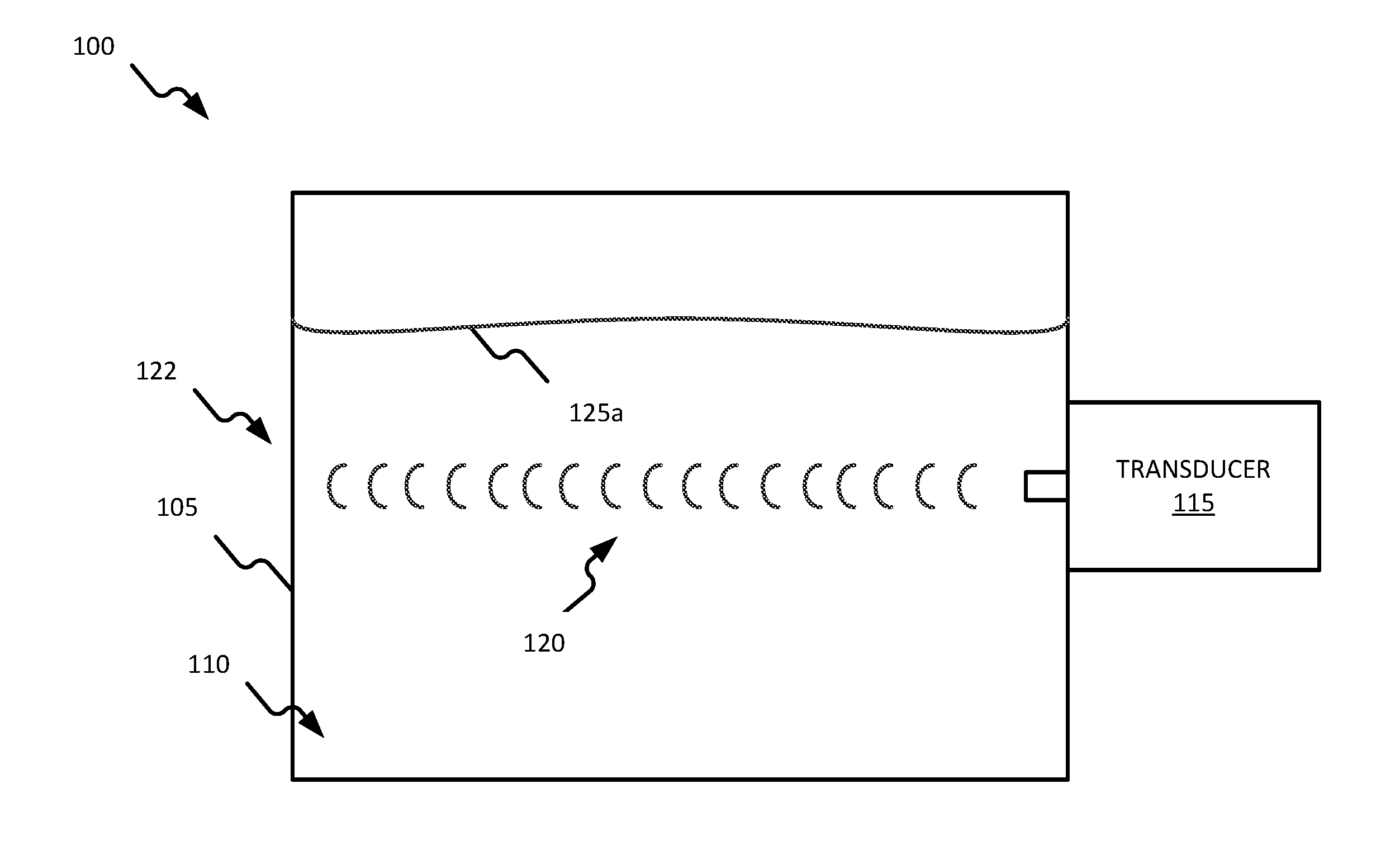
[0011] FIGS. 1A and 1B are block diagrams of a system 100 according to some embodiments. The system 100 includes a tank 105 configured to contain a fluid 110. In some embodiments, the fluid 110 is a liquid, such as but not limited to, hydraulic fluid, diesel exhaust fluid (DEF), brake fluid, oil, fuel, transmission fluid, washer fluid, power steering fluid, and refrigerant.
[0012] The system 100 further includes a transducer 115. The transducer 115 acts as both a transmitter and a receiver. In some embodiments, transducer 115 is an ultrasonic transducer (for example, a piezoelectric ultrasonic transducer (PZT)). Although illustrated as partially outside of tank 105, in some embodiments, the transducer 115 is located completely outside of the 105. In yet other embodiments, the transducer 115 is located completely within the tank 105.
[0013] The transducer 115 is configured to output a sound wave 120 into the tank 105. In the illustrated embodiment, the sound wave 120 is output toward a side wall 122 of the tank 105. The sound wave 120 is then reflected off of the side wall 122 and an echo of the sound wave 120 travels back to the transducer 115. Although illustrated as being located at the middle of the tank 105, in other embodiments, the transducer 115 may be located proximate the top or bottom of the tank 105.
[0014] The fluid 110 includes a surface 125 (which in FIG. 1A is illustrated as surface 125a and in FIG. 1B is illustrated as surface 125b). The amount of fluid in the tank 105 may be such that the surface 125a is above transducer 115. When the surface level 125a is above transducer 115, the sound wave 120 travels through the fluid 110 and the transducer 115 is considered to be "liquid coupled" to the fluid 110. When liquid coupled, the transducer 115 (having dimensions of X and Y) has a first ring time. In some embodiments, the transducer 115 may have a diameter of approximately 14 mm and a thickness of approximately 1 mm. In some embodiments, the first ring time is approximately 1 ms to approximately 3 ms (for example, approximately 2 ms). In other embodiments, the first ring time is less than approximately 20 .mu.s.
[0015] As illustrated in FIG. 1B, the amount of fluid in the tank 105 may be such that surface level 125b is below the transducer 115. When the surface level 125b is below the transducer 115, the sound wave 120 does not travel through the fluid 110 and the transducer 115 is considered to be "air coupled" to the fluid 110, because the sound wave 120 travels through air. When sound wave 120 travels through air, transducer 115 (having the same dimensions of X and Y) has a second ring time. In some embodiments, the second ring time is approximately double the first ring time. For example, in some embodiments, the second ring time is approximately 3 ms or more. In other embodiments, the second ring time is greater than approximately 40 .mu.s.
[0016] FIG. 2 is a block diagram of a control system 200 of the system 100 according to some embodiments. The control system 200 includes a controller 205. The controller 205 is electrically and/or communicatively connected to a variety of modules or components of the system 100. For example, the controller 205 is electrically and/or communicatively connected to the transducer 115, a power supply 210, an input/output (I/O) interface 215, and a temperature sensor 220.
[0017] In the illustrated embodiment, the controller 205 is electrically and/or communicatively connected to the transducer 115 via a transducer driver 225 and a transducer amplifier 230. The transducer driver 225 generates a voltage impulse used to drive the transducer 115 into resonance. The transducer amplifier 230 amplifies and squares an electrical signal from the transducer 115 and outputs the amplified and squared electrical signal (for example, a square wave) to the controller 205. In some embodiments, the transducer driver 225 and the transducer amplifier 230 may be partially, or completely, embedded into the transducer 115 along with piezoelectric material. In other embodiments, the transducer driver 225 and the transducer amplifier 230 may be located separately from the piezoelectric material of transducer 115.
[0018] In some embodiments, the controller 205 includes a plurality of electrical and electronic components that provide power, operational control, and protection to the components and modules within the controller 205 and/or the system 100. For example, the controller 205 includes, among other things, an electronic processor 235 (for example, a microprocessor or another suitable programmable device) and the memory 240.
[0019] The memory 240 includes, for example, a program storage area and a data storage area. The program storage area and the data storage area can include combinations of different types of memory, such as read-only memory (ROM), random access memory (RAM). Various non-transitory computer readable media, for example, magnetic, optical, physical, or electronic memory may be used. The electronic processor 235 is communicatively coupled to the memory 240 and executes software instructions that are stored in the memory 240, or stored on another non-transitory computer readable medium such as another memory or a disc. The software may include one or more applications, program data, filters, rules, one or more program modules, and other executable instructions.
[0020] Power supply 210 is configured to supply nominal power to the controller 205 and/or other components of the system 100. In some embodiments, power supply 210 receives power from an external source (for example, a vehicle power bus). In other embodiments, the power supply 210 receives power from other power sources, for example a battery.
[0021] The I/O interface 215 provides an interface between system 100 and external devices (for example, a vehicle network bus). Depending on the particular application, the I/O interface 215 may support wired communications, wireless communications, or both.
[0022] Temperature sensor 220 is configured to measure a temperature of the fluid 110 and output a temperature signal, indicative of the temperature of the fluid 110, to the controller 205. Sensors suitable for use as the temperature sensor 220 include thermocouples, thermistors resistive temperature sensor, and infrared temperature sensors.
[0023] In operation, the controller 205 controls the transducer driver 225 to generate a voltage impulse used to drive the transducer 115 into resonance and output soundwave 120. The transducer amplifier 230 amplifies and squares an electrical signal from the transducer 115 and outputs the amplified and squared electrical signal to the controller 205. Controller 205 receives the signal from the transducer amplifier 230 and determines a ring time of the transducer 115 based on the signal. Based on the ring time of the transducer 115, the controller 205 determines whether the transducer 115 is liquid coupled or air coupled. For example, if the ring time of the transducer 115 is below a respective ring time threshold, the controller 205 determines that the transducer 115 is liquid coupled, and if the ring time of the transducer 115 is above the respective ring time threshold, the controller 205 determines that the transducer 115 is air coupled. Based on the transducer 115 being liquid coupled or air coupled, the controller 205 may then determine whether the surface level 125 is above, approximately equivalent to, or below the transducer 115.
[0024] A temperature of fluid 110, and/or temperature of the transducer 115, may affect the ring time of the transducer 115. In some embodiments, controller 205 compensates for the effect of temperature on these characteristics. The controller 205 receives a temperature of the fluid 110 from temperature sensor 220. The controller 205 then determines the ring time threshold based on the received temperature.
[0025] FIG. 3 is a flowchart illustrating a process, or operation, 300 of the system 100 according to some embodiments. It should be understood that the order of the steps disclosed in process 300 could vary. In addition, other steps may be added and not all of the steps may be required. Initially, the transducer 115 is activated (block 305). Once the transducer 115 is activated, an operational characteristic of the transducer 115 is determined (block 310). In some embodiments, the operational characteristic of the transducer 115 is a ring time. The controller 205 determines, based on the operational characteristic of the transducer 115, whether the surface level 125 is above or below the transducer 115 (as illustrated in FIG. 1A) (block 315). In some embodiments, the controller 205 determines whether the surface level 125 is above or below the transducer 115 based on a comparison between the operational characteristic and a threshold (for example, a ring time threshold). The controller 205 then outputs an indication based on whether the surface level 125 is above or below the transducer 115 (block 320).
[0026] Thus, embodiments provide, among other things, a system and method for determining a level of a fluid. Various features and advantages of the application are set forth in the following claims.
* * * * *
D00000
D00001
D00002
D00003
D00004
XML
uspto.report is an independent third-party trademark research tool that is not affiliated, endorsed, or sponsored by the United States Patent and Trademark Office (USPTO) or any other governmental organization. The information provided by uspto.report is based on publicly available data at the time of writing and is intended for informational purposes only.
While we strive to provide accurate and up-to-date information, we do not guarantee the accuracy, completeness, reliability, or suitability of the information displayed on this site. The use of this site is at your own risk. Any reliance you place on such information is therefore strictly at your own risk.
All official trademark data, including owner information, should be verified by visiting the official USPTO website at www.uspto.gov. This site is not intended to replace professional legal advice and should not be used as a substitute for consulting with a legal professional who is knowledgeable about trademark law.