Attachable Accessory-retaining Device For A Firearm
Griffith; Benjamin Latham ; et al.
U.S. patent application number 16/275060 was filed with the patent office on 2019-08-15 for attachable accessory-retaining device for a firearm. The applicant listed for this patent is Benjamin Latham Griffith, Arrius Lee Sorbonne. Invention is credited to Benjamin Latham Griffith, Arrius Lee Sorbonne.
| Application Number | 20190249969 16/275060 |
| Document ID | / |
| Family ID | 67541505 |
| Filed Date | 2019-08-15 |


View All Diagrams
| United States Patent Application | 20190249969 |
| Kind Code | A1 |
| Griffith; Benjamin Latham ; et al. | August 15, 2019 |
ATTACHABLE ACCESSORY-RETAINING DEVICE FOR A FIREARM
Abstract
An attachable accessory-retaining device for use with firearms comprises a body having a first retainer housing portion and a second retainer housing portion, an engagement surface for registering a portion of the body against a firearm, and a support surface for engaging a trigger guard of a firearm, the first retainer housing being configured to receive at least one auxiliary accessory and the second retainer housing portion having a cavity for retaining an auxiliary magazine or a clip.
| Inventors: | Griffith; Benjamin Latham; (Salt Lake City, UT) ; Sorbonne; Arrius Lee; (Salt Lake City, UT) | ||||||||||
| Applicant: |
|
||||||||||
|---|---|---|---|---|---|---|---|---|---|---|---|
| Family ID: | 67541505 | ||||||||||
| Appl. No.: | 16/275060 | ||||||||||
| Filed: | February 13, 2019 |
Related U.S. Patent Documents
| Application Number | Filing Date | Patent Number | ||
|---|---|---|---|---|
| 62629894 | Feb 13, 2018 | |||
| Current U.S. Class: | 1/1 |
| Current CPC Class: | F41C 23/22 20130101; F41C 23/16 20130101; F41G 1/35 20130101; F41C 23/12 20130101; F41A 17/38 20130101; F42B 39/02 20130101 |
| International Class: | F42B 39/02 20060101 F42B039/02; F41G 1/35 20060101 F41G001/35 |
Claims
1. An attachable accessory-retaining device for use with firearms, comprising: a body having a first retainer housing portion and a second retainer housing portion, an engagement surface for registering a portion of the body against a firearm and a support surface for engaging a trigger guard of a firearm, wherein the first retainer housing is configured to receive at least one auxiliary accessory and the second retainer housing portion has a cavity for retaining an auxiliary magazine or a clip.
2. The attachable accessory-retaining device of claim 1, wherein the body has a forward portion oriented, in use, toward a muzzle of a firearm and a rearward portion oriented, in use, toward a grip of a firearm.
3. The attachable accessory-retaining device of claim 2, wherein the engagement surface has a longitudinal axis, and wherein the second retainer housing portion has an axis that passes through the cavity and intersects the longitudinal axis of the engagement surface at an acute angle thereto such that the cavity is angled toward a grip of a firearm when in use.
4. The attachable accessory-retaining device of claim 1, wherein the engagement surface further comprises a rail mount element for engaging the rail of a firearm.
5. The attachable accessory-retaining device of claim 1, further comprising a securement device for securing the body to a firearm.
6. The attachable accessory-retaining device of claim 1, wherein the first retainer housing portion is further configured with at least one opening to receive an auxiliary device.
7. The attachable accessory-retaining device of claim 6, wherein the first retainer housing portion is configured with two openings to each receive an auxiliary device therein.
8. The attachable accessory-retaining device of claim 7, further comprising a holding member positioned with each opening to retain an auxiliary device in the opening.
9. The attachable accessory-retaining device of claim 6, wherein the openings are tubular in shape to receive a lighting device or laser device therein.
10. The attachable accessory-retaining device of claim 1, wherein the second retainer housing portion further comprises at least one retention device for engaging a magazine or clip when positioned in the cavity of the second retainer housing portion.
11. The attachable accessory-retaining device of claim 10, wherein the at least one retention device is spring loaded.
12. The attachable accessory-retaining device of claim 1, further comprising at least one laterally extending guard positioned along the first retainer housing portion.
13. The attachable accessory-retaining device of claim 12, wherein the at least one laterally extending guard is positioned at a forward end of the first retainer housing portion oriented, in use, toward a muzzle of a firearm.
14. The attachable accessory-retaining device of claim 1, further comprising a locating member positioned along the first retainer housing portion, providing a support face for the location of auxiliary devices against the body.
15. The attachable accessory-retaining device of claim 1, further comprising a finger guard positioned between the first retainer housing portion and the second retainer housing portion at a forward end of the body.
16. The attachable accessory-retaining device of claim 1, wherein the first retainer housing portion is separable from the second retainer housing portion, the first retainer housing portion including the engagement surface for enabling attachment of the first retainer housing portion to a firearm separate from the second retainer housing portion.
17. The attachable accessory-retaining device of claim 1, wherein the body forms part of a firearm frame and supports a firearm stabilizing device that extends from the body of the accessory-retaining device to a wearer's arm, in use.
18. The attachable accessory-retaining device of claim 17, further comprising a mounting member positioned to extend upwardly from the body and structured to support a sighting system.
19. The attachable accessory-retaining device of claim 18, wherein the mounting member is detachably attachable to the body.
20. A firearm, comprising: a barrel; a grip or stock; a trigger guard; and an accessory-retaining device having a body comprising a first retainer housing portion and a second retainer housing portion, an engagement surface for registering with the barrel and a support surface for engaging the trigger guard, the first retainer housing being configured to receive at least one auxiliary accessory positioned in parallel orientation to the barrel, and the second retainer housing portion having a cavity for removably retaining an auxiliary magazine or a clip.
21. The firearm of claim 20, wherein the second retainer housing is oriented at an angle to the barrel in a direction toward the grip or stock.
22. The firearm of claim 21, wherein the first retainer housing portion is configured with at least one opening to receive a lighting device or laser device therein.
23. The firearm of claim 20, wherein the engagement surface further comprises a rail mount apparatus for slidably attaching the accessory-retaining device to a rail located along the barrel.
24. The firearm of claim 20, further comprising a locating member positioned along the first retainer housing portion, providing a support member for the location of auxiliary devices against the body.
Description
CROSS-REFERENCE TO RELATED APPLICATION
[0001] This application claims priority to U.S. Provisional Patent Application Ser. No. 62/629,894 filed on Feb. 13, 2018, the entirety of which is incorporated by this reference.
FIELD OF THE INVENTION
[0002] This invention relates in general to firearms accessories and, in particular, to a removable housing for retaining auxiliary devices on a firearm, including lighting devices and an additional clip or magazine.
BACKGROUND OF THE INVENTION
[0003] Firearms are typically configured with a means for holding a clip or magazine for feeding consecutive rounds of ammunition into the firing chamber for shooting. As used in this disclosure, "firearms" is meant to include both rifles and handguns in the numerous iterations and configurations in which they are made. Firearms are often used in outdoor situations where lighting is poor or comprised and, therefore, it is desirable to provide means for enhancing the ambient light conditions to improve shooting accuracy.
[0004] In other shooting environments, it may be desirable to enhance the means for locating a target by such means as use of lasers or enhanced scoping devices. The ability to append such lighting or scoping devices to the firearm is desirable in order to free the hands of the user.
[0005] Additionally, it is convenient to have additional ammunition on or about the person in order to replenish or replace the spent clip or magazine that is in use. It is known to provide belts and other wearable devices on which additional clips or magazines may be stored. However, access to an additional clip or magazine that is worn on the person can be inconvenient in the sense that the user must take his eyes off the target in order to reach down and access the new clip or magazine and then position it in the clip or magazine holder of the firearm. Placement of an additional clip or magazine on the firearm enhances access to and placement of the additional clip or magazine in place of the spent clip or magazine.
SUMMARY OF THE INVENTION
[0006] In a first aspect, embodiments are disclosed of an attachable accessory-retaining device for use with firearms, comprising a body having a first retainer housing portion and a second retainer housing portion, an engagement surface for registering a portion of the body against a firearm, and a support surface for engaging a trigger guard of a firearm, wherein the first retainer housing portion is configured to receive at least one auxiliary accessory and the second retainer housing portion has a cavity for retaining an auxiliary magazine or a clip.
[0007] In certain embodiments, the body has a forward portion oriented, in use, toward a muzzle of a firearm and a rearward portion oriented, in use, toward a grip of a firearm.
[0008] In other certain embodiments, the engagement surface has a longitudinal axis, and the second retainer housing portion has an axis that passes through the cavity and intersects the longitudinal axis of the engagement surface at an acute angle thereto such that the cavity is angled toward a grip of a firearm when in use.
[0009] In yet another embodiment, the engagement surface further comprises a rail mount element for engaging the rail of a firearm.
[0010] In still another embodiment, the accessory-retaining device further comprises a securement device for releasably securing the body to a firearm.
[0011] In other embodiments, the first retainer housing portion is further configured with at least one opening to receive an auxiliary device.
[0012] In yet other embodiments, the first retainer housing portion is configured with two openings each configured to receive an auxiliary device therein.
[0013] In still other embodiments, the first retainer housing portion further comprises a holding member positioned with each opening to retain an auxiliary device in the opening.
[0014] In certain embodiments, the openings are tubular in shape to receive a lighting device or laser device therein.
[0015] In some embodiments, the second retainer housing portion further comprises at least one retention device for engaging a magazine or clip when positioned in the cavity of the second retainer housing portion.
[0016] In certain embodiments, the at least one retention device is spring loaded.
[0017] In still other embodiments, the body further comprises at least one laterally extending guard positioned along the first retainer housing portion.
[0018] In certain other embodiments, the at least one laterally extending guard is positioned at a forward end of the first retainer housing portion oriented, in use, toward a muzzle of a firearm.
[0019] In some embodiments, the body further comprises a locating member positioned along the first retainer housing portion, providing a support face for the location of auxiliary devices against the body.
[0020] In yet other embodiments, the accessory-retaining device further comprises a finger guard positioned between the first retainer housing portion and the second retainer housing portion at a forward end of the body.
[0021] In certain embodiments, the first retainer housing portion is separable from the second retainer housing portion, the first retainer housing portion including the engagement surface for enabling attachment of the first retainer housing portion to a firearm separate from the second retainer housing portion.
[0022] In a second aspect, the body of the accessory-retaining device forms part of a firearm frame and supports a firearm stabilizing device that, in use, extends from the body of the accessory-retaining device to a wearer's arm.
[0023] In some embodiments, the accessory-retaining device further comprises a mounting member positioned to extend upwardly from the body and which is structured to support a sighting system.
[0024] In yet other embodiments, the mounting member is detachably attachable to the body of the accessory-retaining device.
[0025] In a third aspect, a firearm comprises a barrel, a grip or stock, a trigger guard, and an accessory-retaining device having a body comprising a first retainer housing portion and a second retainer housing portion, an engagement surface for registering with the barrel and a support surface for engaging the trigger guard, the first retainer housing being configured to receive at least one auxiliary accessory positioned in parallel orientation to the barrel, and the second retainer housing portion having a cavity for removably retaining an auxiliary magazine or a clip.
[0026] In certain embodiments, the second retainer housing portion is oriented at an angle to the barrel of a firearm in a direction toward the grip or stock of the firearm.
[0027] In other embodiments, the first retainer housing portion is configured with at least one opening to receive a lighting device or laser device therein.
[0028] In still other embodiments, the engagement surface further comprises a rail mount apparatus for slidably attaching the accessory-retaining device to a rail located along the barrel.
[0029] In yet other embodiments, the firearm further comprises a locating member positioned along the first retainer housing portion, providing a support face for the location of auxiliary devices against the body.
[0030] Other aspects, features, and advantages will become apparent from the following detailed description when taken in conjunction with the accompanying drawings, which are a part of this disclosure and which illustrate, by way of example, principles of the inventions disclosed.
BRIEF DESCRIPTION OF THE DRAWINGS
[0031] The accompanying drawings facilitate an understanding of the various embodiments, in which,
[0032] FIG. 1 is perspective view of the accessory-retaining device in accordance with this disclosure;
[0033] FIG. 2 is another perspective view of the accessory-retaining device in accordance with this disclosure;
[0034] FIG. 3 is a perspective view of a handgun depicting the attachment of the accessory-retaining device to the handgun;
[0035] FIG. 4 is a further perspective view of a handgun depicting the attachment of the accessory-retaining device to the handgun;
[0036] FIG. 5 is a side view in elevation of a handgun depicting the attachment of the accessory-retaining device to the handgun;
[0037] FIG. 6 is a side view in elevation of the handgun shown in FIG. 5, turned 180.degree., depicting the attachment of the accessory-retaining device to the handgun;
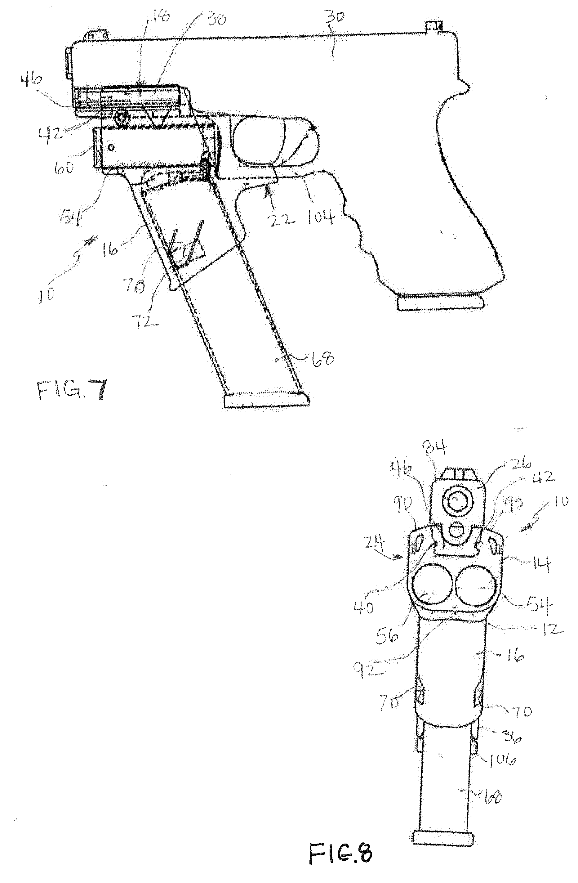
[0038] FIG. 7 is side view in elevation of the handgun, as shown in FIG. 5, with elements of the accessory-retaining device shown in phantom line to illustrate the position of auxiliary devices in the accessory-retaining device;
[0039] FIG. 8 is a front view in elevation of the handgun and accessory-retaining device illustrating the attachment of the latter to the former;
[0040] FIG. 9 is a front view in elevation of the accessory-retaining device, certain elements being shown in phantom to illustrate the positioning of auxiliary devices in the accessory-retaining device;
[0041] FIG. 10 is a rear view in elevation of the handgun as shown in 8, turned 180.degree. degrees;
[0042] FIG. 11 is a plan view of the top of the handgun as shown in FIG. 5;
[0043] FIG. 12 is a bottom view of the handgun as shown in FIG. 5;
[0044] FIG. 13 is an exploded front view in elevation of a further aspect in accordance with the disclosure, depicting the first retainer housing portion separated from the second retainer housing portion;
[0045] FIG. 14 is a front view in elevation of the embodiment shown in FIG. 13 with the first and second retainer housing portions connected together and the first retainer housing portion connected to a firearm;
[0046] FIG. 15 is an exploded side view in elevation of the arrangement depicted in
[0047] FIG. 13;
[0048] FIG. 16 is a side view in elevation of the embodiment shown in FIG. 14 and
[0049] FIG. 15 attached to a firearm;
[0050] FIG. 17 is a side view in elevation of a further aspect of the disclosure comprising a firearm frame with additional accessories configured therewith;
[0051] FIG. 18 is a side view in elevation of the embodiment shown in FIG. 17 when in use with a firearm;
[0052] FIG. 19 is a perspective view of another embodiment of an accessory-retaining device in accordance with this disclosure;
[0053] FIG. 20 is a perspective view of a handgun depicting the attachment of the accessory-retaining device of FIG. 19 to a handgun;
[0054] FIGS. 21, 22 and 23 are front, side and perspective views, respectively, of another embodiment of an accessory-retaining device in accordance with this disclosure;
[0055] FIGS. 24 and 25 are perspective views of another embodiment of an accessory-retaining device in accordance with this disclosure;
[0056] FIG. 26 is a perspective view of another embodiment of an accessory-retaining device in accordance with this disclosure; and
[0057] FIGS. 27, 28 and 29 are perspective views of another embodiment of an accessory-retaining device in accordance with this disclosure.
DETAILED DESCRIPTION OF THE INVENTION
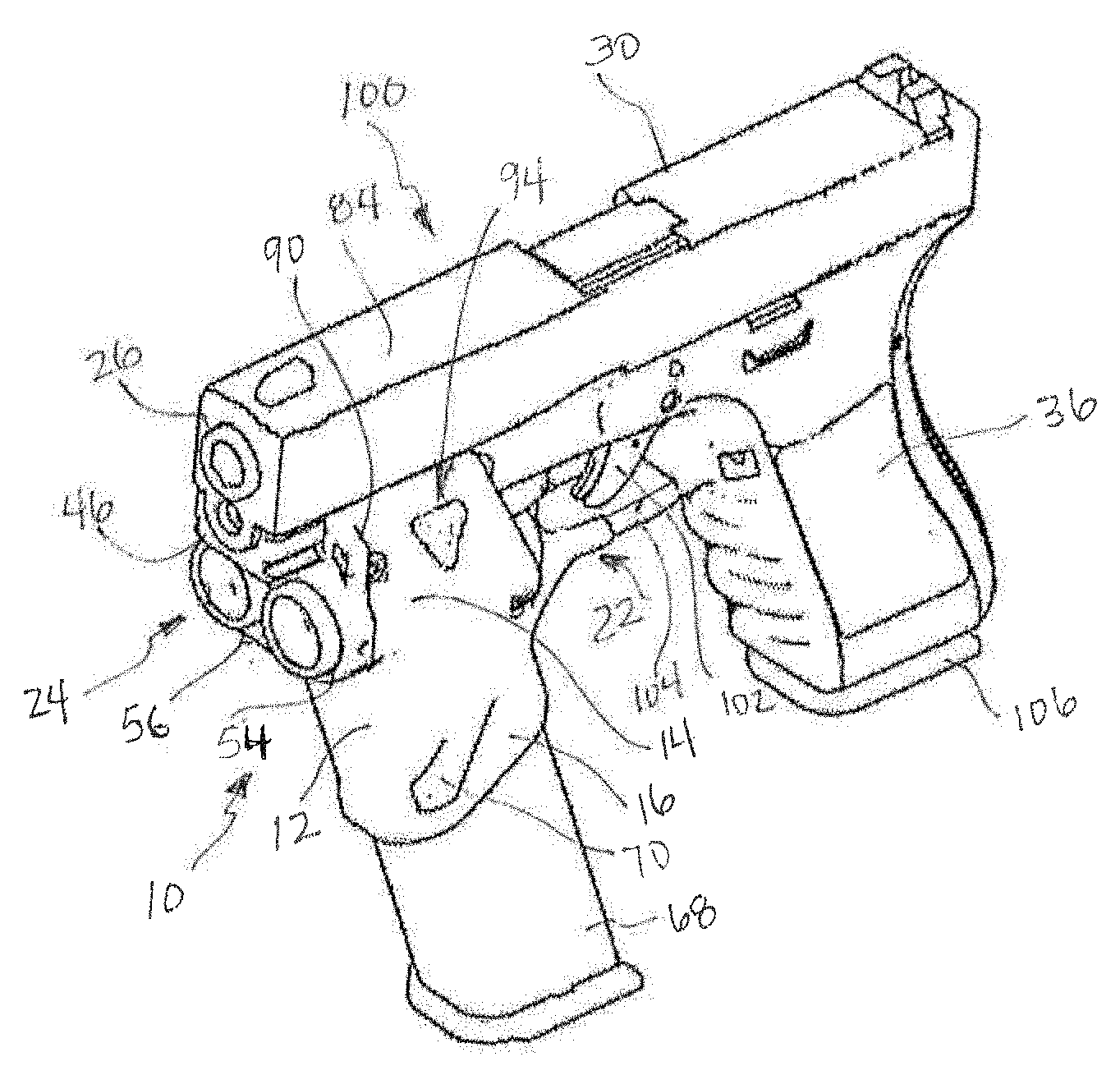
[0058] FIGS. 1 and 2 depict an embodiment of an attachable accessory-retaining device 10 in accordance with the disclosure. The accessory-retaining device 10 comprises a body 12 having a first retainer housing portion 14 and a second retainer housing portion 16. The accessory-retaining device 10 is configured with an engagement surface 18 for registering a portion of the body 12 against a firearm, as described further hereinafter. The accessory-retaining device 10 also has a support surface 22 for engaging the trigger guard of a firearm, as also described further hereinafter.
[0059] The body 12 has a forward portion 24 oriented toward the muzzle 26 of a firearm 30, as shown in FIG. 3, and the body 12 has a rearward portion 32 that is oriented toward the grip 36 of the firearm 30, as shown in FIG. 4, when the accessory-retaining device 10 is attached to a firearm 30. It should be noted that the accessory-retaining device 10 of the disclosure is suitably adaptable to virtually any type of firearm, including rifles and handguns, and is shown and described herein as being configured for attachment to a handgun by way of example only.
[0060] The accessory-retaining device 10 has an engagement surface 18 that is located in proximity to the first retainer housing portion 14. The engagement surface 18 provides the apparatus for attaching the accessory-retaining device 10 to the firearm 30. By way of example, and as shown, the engagement surface 18 may comprise a rail mount arrangement 38, comprised of opposing parallel splines 40, 42 (FIGS. 8 and 9) that are positioned to engage and slide along the rail system 46 of the firearm 30. A securement device 48, such as one or more screws 50, may be provided for releasably securing the body 12 to the firearm 30.
[0061] The rail mount arrangement 38 is but one example for providing an engagement surface 18 and other apparatus or devices may be employed to attach the accessory-retaining device 10 to a firearm. For example, a tubular section sized to slidingly receive the barrel may be provided, or a scissor-type clamp may be employed.
[0062] The first retainer housing portion 14 is configured to receive and retain at least one auxiliary accessory in connection with the body 12 of the accessory-retaining device 10. In one embodiment, the first retainer housing portion 14 may be configured with at least one opening 54 and, as shown, may have two openings 54, 56, that are sized and configured to retain an auxiliary device in one or more openings 54, 56.
[0063] The openings 54, 56, as shown, may be tubular in shape to receive a lighting device or laser device. For example, as illustrated, a small flashlight 60 may be received in one or both openings 54, 56. A holding member 62, such as a boss, may be positioned with each opening 54, 56 to retain the auxiliary device in the opening 54, 56, such as by friction fit. Notably, the openings may be configured in any size, dimension or shape in cross section, and need not be tubular in shape. In the embodiments shown, the openings 54, 56 may be positioned parallel to the long axis of the barrel of the firearm. In certain other embodiments, the openings may be adjustable relative to the orientation of the barrel to train a lighting device or laser device at an angle to the axis of the barrel.
[0064] The second retainer housing portion 16 is formed with a cavity 66 for retaining an auxiliary magazine 68 or a clip therein. The second retainer housing portion 16 further comprises at least one retention device 70 for engaging a magazine 68 or clip when positioned in the cavity 66 of the second retainer housing portion 16. As shown in FIG. 2, two retention devices 70 may be provided, one on each side the second retainer housing portion 16. Each retention device 70 may further be provided with a contact 72, which extends inwardly toward the cavity 66 to engage the magazine 68 or clip positioned in the cavity 66. The at least one retention device 70 may, as shown, be spring loaded by virtue of the retention device 70 being formed by a three-sided cut through the wall 76 of the body 12, which provides a single connection 78 to the body 12.
[0065] It is a particular feature of the accessory-retaining device 10 of the disclosure that the engagement surface 18 has a longitudinal axis 80, which, in use, is generally parallel to the barrel 84 of the firearm 30. Further, the second retainer housing portion 16 has an axis 88 that passes through the cavity 66 and intersects the longitudinal axis 80 of the engagement surface 18 at an acute angle thereto such that the cavity 66 is angled toward the grip 36 of the firearm 30 when the accessory-retaining device 10 is attached to a firearm 30. This orientation of the cavity 66 permits the user enhanced access to the magazine 68 for removal and replacement of the spent magazine without being visually diverted from the target.
[0066] Additional features of the accessory-retaining device 10 include at least one laterally extending guard 90 positioned along the first retainer housing portion 14, preferably positioned at the forward end 24 of the first retainer housing portion 14 and oriented, in use, toward the muzzle 26 of the firearm 30. The laterally extending guard 90 or guards provide a means for resting the user's finger therealong to facilitate grasping the accessory-retaining device 10 in use. The body 12 may further comprise a finger guard 92 positioned between the first retainer housing portion 14 and the second retainer housing portion 16 at a forward end 24 of the body 12.
[0067] The accessory-retaining device 10 may further be configured to facilitate the alignment, engagement, contacting and/or securement of additional auxiliary devices used in connection with the firearms. Thus, a locating member 94 may be positioned along the first retainer housing portion 14, and may be shaped to provide support and alignment for the location of auxiliary devices against the body 12 such as, for example, a spotting scope. For example, the locating member 94 may be configured with a support face 96 against which, or into which, an auxiliary device may be contacted.
[0068] FIGS. 3-8 and 10-12 illustrate the accessory-retaining device 10 of the disclosure in use with a firearm 30, namely a handgun 100. The handgun 100 is generally configured with a barrel 84, a grip 36 and a trigger 102 having a surrounding trigger guard 104. The grip 36 it typically loaded with a removable magazine 106, the bottom of which can be seen in the various drawings.
[0069] It can be seen that the accessory-retaining device 10 is slidably received on the rail 46 of the firearm and the support surface 22 is received in registration with the trigger guard 104, as best seen in FIG. 7. It can also be appreciated from the illustrations of FIGS. 3-7 that the second retainer housing portion 16 is positioned such that an auxiliary magazine 68 positioned in the cavity 66 of the body 10 is positioned at an angle that is generally parallel to the grip 36 of the firearm 30, thereby facilitating expedited access to the auxiliary magazine 68.
[0070] The accessory-retaining device 10 of the disclosure can be made of any number of suitable materials, including thermosetting plastics, ceramics and metals. The body 10 may be cast and/or machined by known methods. It may be especially suitable to form the accessory-retaining device 10 of heavier-weight material to enhance the ability of the accessory-retaining device 10 to offset or counteract the muzzle climb or recoil of the firearm as a result of the positioning of the accessory-retaining device 10 to the forward end of the firearm. Alternatively, the accessory-retaining device 10 may be made of lighter-weight materials and may further include an embedded weight within the body, which is of suitable mass to provide a desired counterweight.
[0071] FIGS. 13 through 16 depict a further embodiment of the accessory-retaining device 200 of the disclosure comprising a first retainer housing portion 202 which is detachable from the second retainer housing portion 204 to provide separate elements. The second retainer housing portion 204 is attachable to the first retainer housing portion 202 by an interlocking means 206, such as a tongue and groove arrangement 208 that enables the second retainer housing portion 204 to be slidingly received onto the first retainer housing portion 202. This assemblage allows the first retainer housing portion 202 to be attached to the firearm 30 alone to provide a single housing arrangement for attaching, for example, lighting devices or laser devices, or additional accessories, without use of the second retainer housing portion 204, which can be added later, as desired.
[0072] In a further aspect of the disclosure, as shown in FIGS. 17 and 18, the body 302 of the accessory-retaining device 300 forms part of a firearm frame 306 and is structured to support a firearm stabilizing device 308 that extends from the body 302 of the accessory-retaining device 300. The first retainer housing portion 312 is adapted to provide an extending brace 314, which, as shown in FIG. 18, extends from the body 302 in a direction away from the muzzle 26 of the firearm 30. A collar portion 316 is positioned at an end 320 of the brace 314 that is opposite from the body 302, the collar portion 316 being adapted to encircle a wearer's arm 322 in use.
[0073] In one embodiment, the body 302 may comprise the elements of a first retainer housing portion and second retainer housing portion in an arrangement as previously described where the two elements are either integrally formed together or are separable. Alternatively, as shown in FIGS. 17 and 18, the body 302 may be adapted to provide accessory-retaining openings 326 in a forward portion of the body 302 adjacent the front portion 328 of the firearm frame 308.
[0074] In a further embodiment, as shown in FIGS. 17 and 18, the body 302 may be adapted to carry or receive a mounting member 330 that is positioned to extend upwardly from the body 302 and is structured to support a sighting system 332 that may typically include optics. In one embodiment, the mounting member 330 may be detachable from the body 302.
[0075] FIGS. 19 and 20 depicts an embodiment of an attachable accessory-retaining device 410 in accordance with the disclosure. The accessory-retaining device 410 comprises a body 412 having a first retainer housing portion 414 and a second retainer housing portion 416. The accessory-retaining device 410 is configured with an engagement surface 418 for registering a portion of the body 412 against a firearm, as described further hereinafter. The accessory-retaining device 410 also has a support surface 422 for engaging the trigger guard of a firearm, as also described further hereinafter.
[0076] The body 412 has a forward portion 424 oriented toward the muzzle 426 of a firearm 430, as shown in FIG. 20, and the body 412 has a rearward portion 432 that is oriented toward the grip 436 of the firearm 430, when the accessory-retaining device 410 is attached to a firearm 430. It should be noted that the accessory-retaining device 410 of the disclosure is suitably adaptable to virtually any type of firearm, including rifles and handguns, and is shown and described herein as being configured for attachment to a handgun by way of example only.
[0077] The accessory-retaining device 410 has an engagement surface 418 that is located in proximity to the first retainer housing portion 414. The engagement surface 418 provides the apparatus for attaching the accessory-retaining device 410 to the firearm 430. By way of example, and as shown, the engagement surface 418 may comprise a rail mount arrangement 438, comprised of opposing parallel splines 440, 442 that are positioned to engage and slide along the rail system 446 of the firearm 430. A securement device 448, such as one or more screws 450, may be provided for releasably securing the body 412 to the firearm 430.
[0078] The rail mount arrangement 438 is but one example for providing an engagement surface 418 and other apparatus or devices may be employed to attach the accessory-retaining device 410 to a firearm. For example, a tubular section sized to slidingly receive the barrel may be provided, or a scissor-type clamp may be employed.
[0079] The first retainer housing portion 414 is configured to receive and retain at least one auxiliary accessory in connection with the body 412 of the accessory-retaining device 410. In one embodiment, the first retainer housing portion 414 may be configured with at least one opening 454 that is sized and configured to retain an auxiliary device in the opening 454.
[0080] The opening 454 may be tubular in shape to receive a lighting device or laser device. For example, as illustrated, a small flashlight 460 may be received in the opening 454 and held therein. Notably, the openings may be configured in any size, dimension or shape in cross section, and need not be tubular in shape. In the embodiments shown, the opening 454 may be positioned parallel to the long axis of the barrel of the firearm. In certain other embodiments, the openings may be adjustable relative to the orientation of the barrel to train a lighting device or laser device at an angle to the axis of the barrel.
[0081] The second retainer housing portion 416 is formed with a cavity 466 for retaining an auxiliary magazine 468 or a clip therein. The second retainer housing portion 416 further comprises at least one retention device 470 for engaging a magazine 468 or clip when positioned in the cavity 466 of the second retainer housing portion 416. The at least one retention device 470 may be spring loaded by virtue of the retention device 470 being formed by a three-sided cut through the wall 476 of the body 412.
[0082] It is a particular feature of the accessory-retaining device 410 of the disclosure that the engagement surface 418 has a longitudinal axis 480, which, in use, is generally parallel to the barrel 484 of the firearm 430. Further, the second retainer housing portion 416 has an axis 488 that passes through the cavity 466 and intersects the longitudinal axis 480 of the engagement surface 418 at an acute angle thereto such that the cavity 466 is angled toward the grip 436 of the firearm 430 when the accessory-retaining device 410 is attached to a firearm 430. This orientation of the cavity 466 permits the user enhanced access to the magazine 468 for removal and replacement of the spent magazine without being visually diverted from the target.
[0083] Additional features of the accessory-retaining device 410 include at least one laterally extending guard 490 positioned along the first retainer housing portion 414, preferably positioned at the forward end 424 of the first retainer housing portion 414 and oriented, in use, toward the muzzle 426 of the firearm 430. The laterally extending guard 490 or guards provide a means for resting the user's finger therealong to facilitate grasping the accessory-retaining device 410 in use. The body 412 may further comprise a finger guard 492 positioned between the first retainer housing portion 414 and the second retainer housing portion 416 at a forward end 424 of the body 412.
[0084] The accessory-retaining device 410 of the disclosure is used with a firearm 430, namely a handgun. The handgun 430 is generally configured with a barrel 484, a grip 436 and a trigger 402 having a surrounding trigger guard 404. The grip 436 is typically loaded with a removable magazine 406, the bottom of which can be seen in the various drawings.
[0085] It can be seen that the accessory-retaining device 410 is slidably received on the rail 446 of the firearm 430 and the support surface 422 is received in registration with the trigger guard 404. It can also be appreciated that the second retainer housing portion 416 is positioned such that an auxiliary magazine 468 positioned in the cavity 466 of the body 410 is positioned at an angle that is generally parallel to the grip 436 of the firearm 430, thereby facilitating expedited access to the auxiliary magazine 468.
[0086] The accessory-retaining device 410 of the disclosure can be made of any number of suitable materials, including thermosetting plastics, ceramics and metals. The body 410 may be cast and/or machined by known methods. It may be especially suitable to form the accessory-retaining device 410 of heavier-weight material to enhance the ability of the accessory-retaining device 410 to offset or counteract the muzzle climb or recoil of the firearm as a result of the positioning of the accessory-retaining device 410 to the forward end of the firearm. Alternatively, the accessory-retaining device 410 may be made of lighter-weight materials and may further include an embedded weight within the body, which is of suitable mass to provide a desired counterweight.
[0087] FIGS. 21, 22 and 23 depict another embodiment of an attachable accessory-retaining device 510 in accordance with the disclosure. The accessory-retaining device 510 is configured similarly to the accessory-retaining device 10 of FIGS. 1 and 2, but without the support surface 22 for engaging the trigger guard of the firearm. The accessory-retaining device 510 comprises a body 512 having a first retainer housing portion 514 and a second retainer housing portion 516. The accessory-retaining device 510 is configured with an engagement surface 518 for registering a portion of the body 512 against a firearm, as described further hereinafter.
[0088] The body 512 has a forward portion 524 oriented toward a muzzle of a firearm, and the body 512 has a rearward portion 532 that is oriented toward a grip of a firearm, when the accessory-retaining device 510 is attached to a firearm 530. It should be noted that the accessory-retaining device 510 of the disclosure is suitably adaptable to virtually any type of firearm, including rifles and handguns, and is shown and described herein as being configured for attachment to a handgun by way of example only.
[0089] The accessory-retaining device 510 has an engagement surface 518 that is located in proximity to the first retainer housing portion 514. The engagement surface 518 provides the apparatus for attaching the accessory-retaining device 510 to a firearm. By way of example, and as shown, the engagement surface 518 may comprise a rail mount arrangement 538, comprised of opposing parallel splines 540, 542 that are positioned to engage and slide along a rail system of a firearm. A securement device 548, such as one or more screws 550, may be provided for releasably securing the body 512 to a firearm.
[0090] The rail mount arrangement 538 is but one example for providing an engagement surface 518 and other apparatus or devices may be employed to attach the accessory-retaining device 510 to a firearm. For example, a tubular section sized to slidingly receive the barrel may be provided, or a scissor-type clamp may be employed.
[0091] The first retainer housing portion 514 is configured to receive and retain at least one auxiliary accessory in connection with the body 512 of the accessory-retaining device 510. In one embodiment, the first retainer housing portion 514 may be configured with openings 554 and 556 that are each sized and configured to retain an auxiliary device in the openings 554 and 556.
[0092] The openings 554 and 556 may be tubular in shape to receive lighting devices and/or laser devices. For example, as illustrated, a small flashlight 460 may be received in the opening 554 and a laser light 561 may be receiving in the opening 556 and held therein. Notably, the openings may be configured in any size, dimension or shape in cross section, and need not be tubular in shape. In the embodiments shown, the openings 554 and 556 may be positioned parallel to the long axis of the barrel of the firearm. In certain other embodiments, the openings may be adjustable relative to the orientation of the barrel to train a lighting device or laser device at an angle to the axis of the barrel.
[0093] The second retainer housing portion 516 is formed with a cavity 566 for retaining an auxiliary magazine or a clip therein. The second retainer housing portion 516 further comprises at least one retention device 570 for engaging a magazine or clip when positioned in the cavity 566 of the second retainer housing portion 516. The at least one retention device 570 may be spring loaded by virtue of the retention device 570 being formed by a three-sided cut through the wall 576 of the body 512.
[0094] It is a particular feature of the accessory-retaining device 510 of the disclosure that the engagement surface 518 has a longitudinal axis 580, which, in use, is generally parallel to the barrel 584 of the firearm 530. Further, the second retainer housing portion 516 has an axis 588 that passes through the cavity 566 and intersects the longitudinal axis 580 of the engagement surface 518 at an acute angle thereto such that the cavity 566 is angled toward the grip of the firearm when the accessory-retaining device 510 is attached to a firearm 530. This orientation of the cavity 566 permits the user enhanced access to the magazine for removal and replacement of the spent magazine without being visually diverted from the target. The body 512 may further comprise a finger guard 592 positioned between the first retainer housing portion 514 and the second retainer housing portion 516 at a forward end 524 of the body 512
[0095] The accessory-retaining device 510 is configured to be slidably received on a rail of a firearm. It can also be appreciated that the second retainer housing portion 516 is positioned such that an auxiliary magazine positioned in the cavity 566 of the body 510 is positioned at an angle that is generally parallel to the grip 536 of the firearm 530, thereby facilitating expedited access to the auxiliary magazine.
[0096] The accessory-retaining device 510 of the disclosure can be made of any number of suitable materials, including thermosetting plastics, ceramics and metals. The body 510 may be cast and/or machined by known methods. It may be especially suitable to form the accessory-retaining device 510 of heavier-weight material to enhance the ability of the accessory-retaining device 510 to offset or counteract the muzzle climb or recoil of the firearm as a result of the positioning of the accessory-retaining device 510 to the forward end of the firearm. Alternatively, the accessory-retaining device 510 may be made of lighter-weight materials and may further include an embedded weight within the body, which is of suitable mass to provide a desired counterweight.
[0097] FIGS. 24 and 25 depict another embodiment of an attachable accessory-retaining device 610 in accordance with the disclosure. The accessory-retaining device 610 comprises a body 612 having a first retainer housing portion 614 and a second retainer housing portion 616. The accessory-retaining device 610 is configured with an engagement surface 618 for registering a portion of the body 612 against a firearm, as described further hereinafter.
[0098] The body 612 has a forward portion 624 oriented toward a muzzle of a firearm, and the body 612 has a rearward portion 632 that is oriented toward a grip of a firearm, when the accessory-retaining device 610 is attached to a firearm. It should be noted that the accessory-retaining device 610 of the disclosure is suitably adaptable to virtually any type of firearm, including rifles and handguns, and is shown and described herein as being configured for attachment to a handgun by way of example only.
[0099] The accessory-retaining device 610 has an engagement surface 618 that is located in proximity to the first retainer housing portion 614. The engagement surface 618 provides the apparatus for attaching the accessory-retaining device 610 to a firearm. By way of example, and as shown, the engagement surface 618 may comprise a rail mount arrangement 638, comprised of opposing parallel splines 640, 642 that are positioned to engage and slide along a rail system of a firearm. A securement device, such as one or more screws, may be provided for releasably securing the body 612 to a firearm.
[0100] The rail mount arrangement 638 is but one example for providing an engagement surface 618 and other apparatus or devices may be employed to attach the accessory-retaining device 610 to a firearm. For example, a tubular section sized to slidingly receive the barrel may be provided, or a scissor-type clamp may be employed.
[0101] The first retainer housing portion 614 is configured to retain at least one auxiliary accessory in connection with the body 612 of the accessory-retaining device 610. In one embodiment, the first retainer housing portion 614 may be configured with a rail system 654, similar to the rail system on the firearm that extends from the front portion 624. The rail system 654 is sized and configured to attach to a rail attachment system 656, similar to the rail mount arrangement 638, on the top portion of an auxiliary device 560.
[0102] For example, as illustrated, a small flashlight 660 may be attached to the rail system 654. That is, the body 670 of the flashlight is provided with a rail attachment system 656 on its upper side to engage with and be retained by the rail system 654. The rail systems 654 and 656 are positioned parallel to the long axis of the barrel of the firearm.
[0103] The second retainer housing portion 616 is formed with a cavity 666 for retaining an auxiliary magazine or a clip therein. The second retainer housing portion 616 further comprises at least one retention device 670 for engaging a magazine or clip when positioned in the cavity 666 of the second retainer housing portion 616. The at least one retention device 670 may be spring loaded by virtue of the retention device 670 being formed by a three-sided cut through the wall 676 of the body 612.
[0104] It is a particular feature of the accessory-retaining device 610 of the disclosure that the engagement surface 618 has a longitudinal axis 680, which, in use, is generally parallel to the barrel of the firearm. Further, the second retainer housing portion 616 has an axis 688 that passes through the cavity 666 and intersects the longitudinal axis 680 of the engagement surface 618 at an acute angle thereto such that the cavity 666 is angled toward the grip of the firearm when the accessory-retaining device 610 is attached to a firearm. This orientation of the cavity 666 permits the user enhanced access to the magazine for removal and replacement of the spent magazine without being visually diverted from the target.
[0105] The accessory-retaining device 610 is configured to be slidably received on a rail of a firearm. It can also be appreciated that the second retainer housing portion 616 is positioned such that an auxiliary magazine positioned in the cavity 666 of the body 610 is positioned at an angle that is generally parallel to the grip of the firearm, thereby facilitating expedited access to the auxiliary magazine.
[0106] The accessory-retaining device 610 of the disclosure can be made of any number of suitable materials, including thermosetting plastics, ceramics and metals. The body 610 may be cast and/or machined by known methods. It may be especially suitable to form the accessory-retaining device 610 of heavier-weight material to enhance the ability of the accessory-retaining device 610 to offset or counteract the muzzle climb or recoil of the firearm as a result of the positioning of the accessory-retaining device 610 to the forward end of the firearm. Alternatively, the accessory-retaining device 610 may be made of lighter-weight materials and may further include an embedded weight within the body, which is of suitable mass to provide a desired counterweight.
[0107] FIG. 26 depicts another embodiment of an attachable accessory-retaining device 710 in accordance with the disclosure. The accessory-retaining device 710 comprises a body 712 having a first retainer housing portion 714 and a second retainer housing portion 716. The accessory-retaining device 710 is configured with an engagement surface 718 for registering a portion of the body 712 against a firearm, as described further hereinafter.
[0108] The body 712 has a forward portion 724 oriented toward a muzzle of a firearm, and the body 712 has a rearward portion 732 that is oriented toward a grip of a firearm, when the accessory-retaining device 710 is attached to a firearm. It should be noted that the accessory-retaining device 710 of the disclosure is suitably adaptable to virtually any type of firearm, including rifles and handguns, and is shown and described herein as being configured for attachment to a handgun by way of example only.
[0109] The accessory-retaining device 710 has an engagement surface 718 that is located in proximity to the first retainer housing portion 714. The engagement surface 718 provides the apparatus for attaching the accessory-retaining device 710 to a firearm. By way of example, and as shown, the engagement surface 718 may comprise a rail mount arrangement 738, comprised of opposing parallel splines 740, 742 that are positioned to engage and slide along a rail system of a firearm. A securement device, such as one or more screws, may be provided for releasably securing the body 712 to a firearm.
[0110] The rail mount arrangement 738 is but one example for providing an engagement surface 718 and other apparatus or devices may be employed to attach the accessory-retaining device 710 to a firearm. For example, a tubular section sized to slidingly receive the barrel may be provided, or a scissor-type clamp may be employed.
[0111] The first retainer housing portion 714 is configured to retain at least two auxiliary accessories in connection with the body 612, on either side thereof, of the accessory-retaining device 710. In one embodiment, the first retainer housing portion 614 may be configured with a first rail 754, similar to the rail system on the firearm, and a second rail 756. The rails 754 and 756 are sized and configured to attach to a rail attachment system 756, similar to the rail mount arrangement 738, on the top portion of an auxiliary device 760.
[0112] For example, as illustrated, a small flashlight 760 may be attached to the rail system 754. That is, the body 771 of the flashlight 760 is provided with a rail attachment system 756 on its side to engage with and be retained by the rail system 754. The rails 754 and 656 are positioned parallel to the long axis of the barrel of the firearm.
[0113] The second retainer housing portion 716 is formed with a cavity 766 for retaining an auxiliary magazine or a clip therein. The second retainer housing portion 716 further comprises at least one retention device 770 for engaging a magazine or clip when positioned in the cavity 766 of the second retainer housing portion 716. The at least one retention device 770 may be spring loaded by virtue of the retention device 770 being formed by a three-sided cut through the wall 776 of the body 712.
[0114] It is a particular feature of the accessory-retaining device 710 of the disclosure that the engagement surface 718 has a longitudinal axis, which, in use, is generally parallel to the barrel of the firearm. Further, the second retainer housing portion 716 has an axis that passes through the cavity 766 and intersects the longitudinal axis of the engagement surface 718 at an acute angle thereto such that the cavity 766 is angled toward the grip of the firearm when the accessory-retaining device 710 is attached to a firearm. This orientation of the cavity 766 permits the user enhanced access to the magazine for removal and replacement of the spent magazine without being visually diverted from the target.
[0115] The accessory-retaining device 710 is configured to be slidably received on a rail of a firearm. It can also be appreciated that the second retainer housing portion 716 is positioned such that an auxiliary magazine positioned in the cavity 766 of the body 710 is positioned at an angle that is generally parallel to the grip of the firearm, thereby facilitating expedited access to the auxiliary magazine.
[0116] The accessory-retaining device 710 of the disclosure can be made of any number of suitable materials, including thermosetting plastics, ceramics and metals. The body 710 may be cast and/or machined by known methods. It may be especially suitable to form the accessory-retaining device 710 of heavier-weight material to enhance the ability of the accessory-retaining device 710 to offset or counteract the muzzle climb or recoil of the firearm as a result of the positioning of the accessory-retaining device 710 to the forward end of the firearm. Alternatively, the accessory-retaining device 710 may be made of lighter-weight materials and may further include an embedded weight within the body, which is of suitable mass to provide a desired counterweight.
[0117] FIGS. 27, 28 and 29 depict another embodiment of an attachable accessory-retaining device 810 in accordance with the disclosure. The accessory-retaining device 810 comprises a body 812 comprising a housing 813 having a first retainer housing portion 814 and a second retainer housing portion 816. An auxiliary device 860, for example, as illustrated, a small flashlight 860 is configured to be directly attached to the rail system of a firearm. The body 871 of the flashlight 860 is provided with a rail attachment system 856 on its top side to engage with and be retained by the rail system of a firearm. The rail system 856 is positioned parallel to the long axis of the barrel of the firearm.
[0118] As shown in FIG. 27, the flashlight 860 is inserted into the housing 813 with the splines 857 and 859 of the rail system 856 extending through apertures 861 and 863 in the top surface of the housing 813. The splines 857 and 859 extend far enough above the top surface 867 of the housing 813 to engage with the rail system of a firearm. Thus, it is the flashlight 860 that holds the housing 813 to the firearm.
[0119] The body 812 has a forward portion 824 oriented toward a muzzle of a firearm, and the body 812 has a rearward portion 832 that is oriented toward a grip of a firearm, when the accessory-retaining device 810 is attached to a firearm. It should be noted that the accessory-retaining device 810 of the disclosure is suitably adaptable to virtually any type of firearm, including rifles and handguns, and is shown and described herein as being configured for attachment to a handgun by way of example only.
[0120] The first retainer housing portion 814 is configured to retain the auxiliary accessory 860 in connection with the body 812 of the accessory-retaining device 810. The auxiliary accessory 860 slides from the rear end 832 of the housing 813 into the housing until the lens 871 of the accessory 860 extends through the opening 873 of the housing 813.
[0121] The second retainer housing portion 816 is formed with a cavity 866 for retaining an auxiliary magazine or a clip therein. The second retainer housing portion 816 further comprises at least one retention device 870 for engaging a magazine or clip when positioned in the cavity 866 of the second retainer housing portion 816. The at least one retention device 870 may be spring loaded by virtue of the retention device 870 being formed by a three-sided cut through the wall 876 of the body 812.
[0122] It is a particular feature of the accessory-retaining device 810 of the disclosure that the engagement surface 818 has a longitudinal axis, which, in use, is generally parallel to the barrel of the firearm. Further, the second retainer housing portion 816 has an axis that passes through the cavity 866 and intersects the longitudinal axis of the engagement surface 818 at an acute angle thereto such that the cavity 866 is angled toward the grip of the firearm when the accessory-retaining device 810 is attached to a firearm. This orientation of the cavity 866 permits the user enhanced access to the magazine for removal and replacement of the spent magazine without being visually diverted from the target.
[0123] The accessory-retaining device 810 is configured to be slidably received on a rail of a firearm. It can also be appreciated that the second retainer housing portion 816 is positioned such that an auxiliary magazine positioned in the cavity 866 of the body 810 is positioned at an angle that is generally parallel to the grip of the firearm, thereby facilitating expedited access to the auxiliary magazine.
[0124] The accessory-retaining device 810 of the disclosure can be made of any number of suitable materials, including thermosetting plastics, ceramics and metals. The body 810 may be cast and/or machined by known methods. It may be especially suitable to form the accessory-retaining device 810 of heavier-weight material to enhance the ability of the accessory-retaining device 810 to offset or counteract the muzzle climb or recoil of the firearm as a result of the positioning of the accessory-retaining device 810 to the forward end of the firearm. Alternatively, the accessory-retaining device 810 may be made of lighter-weight materials and may further include an embedded weight within the body, which is of suitable mass to provide a desired counterweight.
[0125] In the foregoing description of certain embodiments, specific terminology has been resorted to for the sake of clarity. However, the disclosure is not intended to be limited to the specific terms so selected, and it is to be understood that each specific term includes other technical equivalents, which operate in a similar manner to accomplish a similar technical purpose. Terms such as "left" and right", "front" and "rear", "above" and "below" and the like are used as words of convenience to provide reference points and are not to be construed as limiting terms.
[0126] In this specification, the word "comprising" is to be understood in its "open" sense, that is, in the sense of "including", and thus not limited to its "closed" sense, that is the sense of "consisting only of". A corresponding meaning is to be attributed to the corresponding words "comprise", "comprised" and "comprises" where they appear.
[0127] In addition, the foregoing describes only some embodiments of the inventions, and alterations, modifications, additions and/or changes can be made thereto without departing from the scope and spirit of the disclosed embodiments, the embodiments being illustrative and not restrictive.
[0128] Furthermore, inventions have been described in connection with what are presently considered to be the most practical and preferred embodiments, it is to be understood that the invention is not to be limited to the disclosed embodiments, but on the contrary, is intended to cover various modifications and equivalent arrangements included within the spirit and scope of the inventions. Also, the various embodiments described above may be implemented in conjunction with other embodiments, e.g., aspects of one embodiment may be combined with aspects of another embodiment to realize yet other embodiments. Further, each independent feature or component of any given assembly may constitute an additional embodiment, and various collections of the described elements may be arranged to consist only of those elements as defined by the claims.
* * * * *
D00000
D00001
D00002
D00003
D00004
D00005
D00006
D00007
D00008
D00009
D00010
D00011
D00012

D00013

D00014

XML
uspto.report is an independent third-party trademark research tool that is not affiliated, endorsed, or sponsored by the United States Patent and Trademark Office (USPTO) or any other governmental organization. The information provided by uspto.report is based on publicly available data at the time of writing and is intended for informational purposes only.
While we strive to provide accurate and up-to-date information, we do not guarantee the accuracy, completeness, reliability, or suitability of the information displayed on this site. The use of this site is at your own risk. Any reliance you place on such information is therefore strictly at your own risk.
All official trademark data, including owner information, should be verified by visiting the official USPTO website at www.uspto.gov. This site is not intended to replace professional legal advice and should not be used as a substitute for consulting with a legal professional who is knowledgeable about trademark law.