Steam Generator And Reactor
Mahawili; Imad
U.S. patent application number 16/392917 was filed with the patent office on 2019-08-15 for steam generator and reactor. The applicant listed for this patent is Qolibri, Inc.. Invention is credited to Imad Mahawili.
| Application Number | 20190249863 16/392917 |
| Document ID | / |
| Family ID | 62025398 |
| Filed Date | 2019-08-15 |


| United States Patent Application | 20190249863 |
| Kind Code | A1 |
| Mahawili; Imad | August 15, 2019 |
STEAM GENERATOR AND REACTOR
Abstract
A method of producing an active chemical species, steam or superheated steam includes flowing one or more fluids through a conduit, locating one or more incandescent lights in close proximity to the conduit, and using at least a portion of the heat emitted from the one or more incandescent lights to heat the one or more fluids flowing through the conduit so that the fluid or fluids are disassociated into chemical components, associated into a new compound, or converted into steam.
| Inventors: | Mahawili; Imad; (Roseville, CA) | ||||||||||
| Applicant: |
|
||||||||||
|---|---|---|---|---|---|---|---|---|---|---|---|
| Family ID: | 62025398 | ||||||||||
| Appl. No.: | 16/392917 | ||||||||||
| Filed: | April 24, 2019 |
Related U.S. Patent Documents
| Application Number | Filing Date | Patent Number | ||
|---|---|---|---|---|
| PCT/US2017/057356 | Oct 19, 2017 | |||
| 16392917 | ||||
| 62412526 | Oct 25, 2016 | |||
| Current U.S. Class: | 1/1 |
| Current CPC Class: | F24H 1/10 20130101; H05B 3/0052 20130101; F22B 1/28 20130101; F24H 1/142 20130101; F24H 1/12 20130101; F22B 1/281 20130101; F22B 1/282 20130101; F22B 1/30 20130101; F24H 2250/14 20130101; F24H 1/162 20130101; F24H 1/43 20130101 |
| International Class: | F22B 1/28 20060101 F22B001/28 |
Claims
1. A method of producing an active chemical species, steam or superheated steam comprises: flowing one or more fluids through a conduit; locating one or more incandescent lights in close proximity to the conduit; and using at least a portion of the heat emitted from the one or more incandescent lights to heat the one or more fluids flowing through the conduit so that the fluid or fluids are disassociated into chemical components, associated into a new compound, or converted into steam.
2. The method according to claim 1, wherein the locating one or more incandescent lights includes locating one or more tungsten halogen lamps in close proximity to the conduit.
3. The method according to claim 2, wherein the locating one or more tungsten halogen lamps in close proximity to the conduit includes locating at least two tungsten halogen lamps in close proximity to the conduit, optionally locating at least four tungsten halogen lamps in close proximity to the conduit, or optionally locating six or more tungsten halogen lamps in close proximity to the conduit.
4. The method according to claim 1, wherein the locating the lamps includes locating the lamps around the conduit.
5. The method according to claim 1, or further comprising surrounding the lamps with the conduit.
6. The method according to claim 2, wherein the locating the lamps may include surrounding the lamps with a first portion of the conduit, and locating the lamps around a second portion of the conduit.
7. The method according to claim 2, wherein the locating the lamps includes surrounding the lamps with a first portion of the conduit, and surrounding the first portion of the conduit with a second portion of the conduit.
8. The method according to claim 7, wherein the flowing one or more fluids through the conduit includes flowing the one or more fluids into the second portion of the conduit wherein the second portion of the conduit forms the inlet to the conduit.
9. The method according to claim 1, wherein the flowing the water includes flowing one or more fluids through two conduits, and locating the light in close proximity to at least one of the conduits, and optionally both conduits.
10. The method according to claim 1, further comprising locating radiation shields between the end of the lamps and the conduit to shield the ends of the lamps from at least some of the radiation emitted by the lamps and heat emitted from the conduit.
11. A generator comprising: a conduit having an inlet and an outlet, with the inlet being in fluid communication with a source of one or more fluids; and one or more incandescent lights located in close proximity to the conduit wherein at least some of the heat emitted from the one or more incandescent lights is used to heat the one or more fluids flowing through the conduit.
12. The generator according to claim 11, wherein the one or more incandescent lights includes one or more tungsten halogen lamps located in close proximity to the conduit.
13. The generator according to claim 12, wherein the one or more tungsten halogen lamps includes at least two tungsten halogen lamps in close proximity to the conduit, optionally at least four tungsten halogen lamps are in close proximity to the conduit, or optionally six or more tungsten halogen lamps are in close proximity to the conduit.
14. The generator according to claim 11, wherein the lamps are arranged the around the conduit.
15. The generator according to claims 12, wherein the generator further includes first and second mounting bases for holding the opposed ends of the lamps.
16. The generator according to claim 15, wherein the bases are formed from a ceramic material, such as a machineable glass ceramic.
17. The generator according to claim 12, wherein the conduit includes first and second portions, the first portion extending between the lamps with the lamps surrounding the first portion of the conduit, and the second portion surrounding the lamps.
Description
TECHNICAL FIELD AND BACKGROUND OF THE INVENTION
[0001] Steam generators are devices that use heat to boil liquid water and convert it into steam. The heat is typically from fossil fuels, electricity, nuclear energy, or renewal energy. There are number of different types of steam generators that operate under a wide range of operating pressures to achieve a wide range of steam quality production. Most steam generators are high pressure vessels constructed out of a variety of steels. Steam generators take a long time typically in the range of several minutes to hours to achieve steam at a predetermined stable operating pressure and temperature.
[0002] For example, small steam generators, which typically use electricity, take several minutes to produce saturated steam at approximately one atmosphere and nearly 100 degrees centigrade. Small superheated steam generators, which typically output steam at steam at about 500 degrees centigrade or greater, take a much longer time to achieve the desired boiler pressure that produces the desired superheated steam temperatures.
[0003] One of superheated steam's value lies in its ability to release tremendous quantities of internal energy that can be used to drive mechanical systems, such as turbines and reciprocating piston engines. By remaining above the condensation temperature of water vapor at the pressures at which these systems operate, superheated steam avoids the formation of water droplets, which droplets would otherwise damage these systems due to their incompressible nature (at those operating pressures). Therefore, of prime importance is the compressible nature of superheated steam, especially when driving a reciprocating engine or turbine.
[0004] Therefore, this delay can limit the application of superheated steam in processes that demand rapid superheated steam injection, such as in typical semiconductor manufacturing.
[0005] Accordingly, there is a need for a faster way to produce steam, especially superheated steam.
SUMMARY
[0006] In one embodiment, a method of producing an active chemical species, steam or superheated steam, includes flowing one or more fluids through a conduit, locating one or more incandescent lights in close proximity to the conduit, and using at least a portion of the heat emitted from the one or more incandescent lights to heat the fluid or fluids flowing through the conduit so that the fluid or fluids are disassociated into chemical components, associated into a new compound, or converted into steam.
[0007] In one aspect, locating one or more incandescent lights includes locating one or more tungsten halogen lamps in close proximity to the conduit.
[0008] In a further aspect, locating one or more tungsten halogen lamps in close proximity to the conduit includes locating at least two tungsten halogen lamps in close proximity to the conduit, optionally locating at least four tungsten halogen lamps in close proximity to the conduit, or optionally locating six or more tungsten halogen lamps in close proximity to the conduit.
[0009] In another aspect, locating the lamps includes locating the lamps around the conduit.
[0010] In yet another aspect, the method includes surrounding the lamps with the conduit.
[0011] According to yet another aspect, locating the lamps may include surrounding the lamps with a first portion of the conduit, and locating the lamps around a second portion of the conduit.
[0012] In yet another embodiment, locating the lamps may include surrounding the lamps with a first portion of the conduit, and surrounding the first portion of the conduit with a second portion of the conduit.
[0013] In a further aspect, flowing the fluid or fluids through the conduit includes flowing the fluid or fluids into the second portion of the conduit wherein the second portion of the conduit forms the inlet to the conduit. In this manner, the second portion of the conduit forms an insulation layer around the first portion of the conduit.
[0014] In yet another embodiment, flowing the fluid or fluids includes flowing fluid or fluids through two conduits, and locating the light in close proximity to at least one of the conduits, and optionally both conduits.
[0015] In any of the above, the method may include locating radiation shields between the end of the lamps and the conduit to shield the ends of the lamps from at least some of the radiation emitted by the lamps and heat emitted from the conduit.
[0016] In another embodiment, a generator includes a conduit having an inlet and an outlet and one or more incandescent lights located in close proximity to the conduit. The inlet is in fluid communication with a source of fluid or fluids wherein at least some of the heat emitted from the one or more incandescent lights is used to heat the fluid or fluids flowing through the conduit.
[0017] In one aspect, the one or more incandescent lights include one or more tungsten halogen lamps located in close proximity to the conduit.
[0018] In a further aspect, the one or more tungsten halogen lamps includes at least two tungsten halogen lamps in close proximity to the conduit, optionally at least four tungsten halogen lamps are in close proximity to the conduit, or optionally six or more tungsten halogen lamps are in close proximity to the conduit.
[0019] In another aspect, the lamps are arranged around the conduit. For example, the generator further includes first and second mounting bases for holding the opposed ends of the lamps. In one aspect, the bases are formed from a ceramic material, such as a machineable glass ceramic.
[0020] In yet another aspect, the conduit includes two portions--a first portion that extends between the lamps with the lamps surrounding the first portion of the conduit, and a second portion that surrounds the lamps.
[0021] Accordingly, the generator can quickly heat and convert gases and/or liquids, such water into steam, namely superheated steam.
DETAILED DESCRIPTION OF THE DRAWINGS
[0022] FIG. 1 is a schematic drawing of a typical commercial tungsten halogen high temperature lamp;
[0023] FIG. 2 is an enlarged plan view of an end base for a plurality of lamps;
[0024] FIG. 2A is a cross-section view taken through line IIA-IIA of FIG. 2;
[0025] FIG. 3 is a schematic drawing of the lamp array system mounted between two end bases;
[0026] FIG. 4 is a schematic drawing of a lamp array system with a process conduit extending there through;
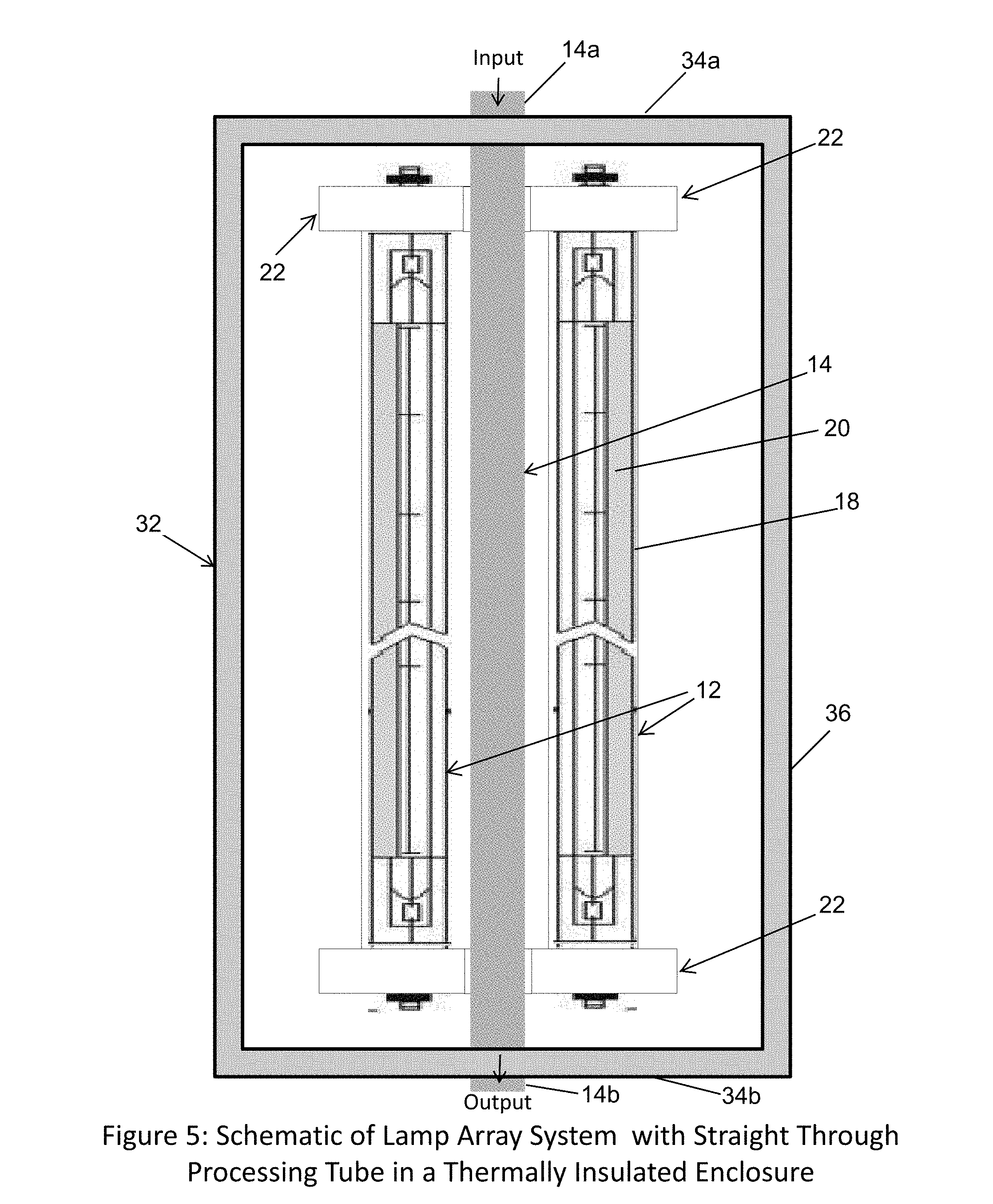
[0027] FIG. 5 is a schematic drawing of the lamp array system and process conduit of FIG. 4 shown housed in enclosure;
[0028] FIG. 6 is a schematic drawing of the lamp array system with another embodiment of a process conduit;
[0029] FIG. 7 is a schematic drawing of the lamp array system with a third embodiment of a process conduit; and
[0030] FIG. 8 is a schematic drawing of the lamp array system with a fourth embodiment of the process conduit.
DETAILED DESCRIPTION OF THE PREFERRED EMBODIMENTS
[0031] Referring to FIG. 4, the numeral 10 generally designates a generator or reactor that heats a fluid or fluids, such as liquids or gases. The illustrated embodiment is described herein in the context of a steam generator that heats water to generate steam, specifically superheated steam, but it should be understood that a gas or gases or a gas and liquid may be heated using the same technology to disassociate or associate the gas, gases and/or liquids into other desired compounds. Further, the present steam generator can heat water to generate steam, specifically superheated steam, at a rapid rate. For example, steam generator 10 can generate superheated steam in seconds versus minutes, which is associated with conventional steam generators. As will be more fully described below, generator 10 is configured to produce nearly instantaneous steam and, more specifically, nearly instantaneous superheated steam at about one atmosphere and at a temperature in a range of 100 C to several hundred degrees centigrade. Several examples of the amount of steam, the temperature of the steam, and the rate of steam production are provided below.
[0032] As best seen in FIG. 4, generator 10 includes one or more incandescent lights 12 (see FIG. 1) that are located in close proximity to a process conduit 14 for directing heat to the process conduit. Process conduit 14 includes an inlet or input 14a for coupling to a source of gas and/or liquid, such as water, and an outlet 14b from which the heated product, such as steam, is output from the generator. For example, suitable gases for association or disassociation may include gases associated with, for example, semiconductor processing.
[0033] Referring to FIGS. 3 and 4, power is delivered to the one or more incandescent lights 12 by a computer-based control system 16, which is coupled to a power supply (not shown) and to the electrodes of the lamps to regulate the power delivered to the light or lights, for example based on the water flow rate and the desired superheated steam outlet temperature. Computer-based control system 16 includes a microprocessor based controller and may include one or more a sensors in communication with the controller to detect one or more process parameters. For example, computer-based control system 16 may include one or more sensors to detect the flow rate of the water at or near the input and one or more temperature sensors to detect the steam's temperature at or near the outlet, and optionally to detect the temperature of the conduit and/or the lamps. Computer-based control system 16 may also include other electronic components that are programmed to carry out the functions described herein, or that support the microprocessor and/or other electronics. The other electronic components include, but are not limited to, one or more discrete circuitry, integrated circuits, application specific integrated circuits (ASICs) and/or other hardware, software, or firmware, as would be known to one of ordinary skill in the art. Such components can be physically configured in any suitable manner, such as by mounting them to one or more circuit boards, or arranging them in other manners, whether combined into a single unit at the generator in a control unit or distributed across multiple control units. Such components may be located at the generator or they may reside separately from the generator, for example, in remote location from the generator. When located separately, the components may communicate using any suitable serial or parallel communication protocol.
[0034] In the illustrated embodiment, lights 12 comprise a plurality of tungsten halogen lamps 18 (e.g. see FIGS. 1, 3, and 4), including for example tungsten halogen high temperature lamps. A halogen lamp is incandescent tungsten lamp that has tungsten filament and a small amount of halogen gas, such as iodine or bromine added. The addition of the halogen gases to the tungsten filament produces a halogen cycle chemical reaction that increases the operating life of the lamp. High temperature lamps are commercially available from a variety of companies, for example Fannon in the US or Ushio of Japan.
[0035] Optionally, referring to FIG.1, lamps 18 may be manufactured with a totally clear quartz cylindrical bulb or housing 18a or may have portion of the inside of the housing coated with a film 20, such as partial gold thin-film, to focus the energy emitted from the filament inside the housing in a desired direction. Alternately or in addition, an external reflective coating, such as a thin gold film, may be applied to the exterior of the housing. Lamps 18, which as noted are conventional, may include a ceramic cap 18b on each end into which the ends of the filament extend and couple to electrodes 18c, 18d for coupling the respective lamp to a power supply as controlled by control system 16.
[0036] To support the lamps in a spaced relationship around the process conduit 14, generator 10 includes first and second end bases 22, such as shown in FIG. 2. Each end base 22 may be formed from a ceramic material, including mica or a machineable ceramic material, such as a machineable glass ceramic, which is available under the trademark Macor. As best seen in FIGS. 2 and 2A, end bases 22 include a plurality of openings 24 through which the lamp electrodes extend for coupling the power supply. In the illustrated embodiment, end bases 22 are formed from a disk shaped member with an optional central opening 26 for receiving the process conduit and an annular recess 28 that extends around opening 26 for receiving the respective end caps of lamps 18. As would be understood the shape, size, number of openings and location of the openings in the end bases may vary depending on the size and number of lamps that are used, and the type of process conduit, as will be more fully described below.
[0037] Openings 24 are located in an annular recess 28 of end base 22 and arranged around radially spaced from opening 26 so that when the lamps are mounted to the respective end bases 22, lamps 18 will be arranged around opening 26 to form a central passage 30 (FIGS. 3 and 4) there between to receive process conduit 14. Thus, in this embodiment, the lamps 18 surround the process conduit 14. Hence, the reflective coating 20 may be applied to the outer side of the respective lamps so that the heat emitted by the lamps is directed inwardly toward the process conduit. The number of lamps may be varied, including at least two lamps, at least four lamp, and optionally six or more lamps, as shown in the illustrated embodiment.
[0038] To increase the heat transfer, lamp 18 are located in close proximity to process conduit 14 in FIG. 4. For example, the term close proximity means in a range of 5 to 10 mm, in a range of 2 to 30 mm, or optionally in a range of 1 to 7 mm. In this manner when combined with the use of the reflective coatings, most if not all, the heat emitted from the lamps is directed toward the process conduit.
[0039] Referring again to FIG. 4, in the illustrated embodiment, process conduit 14 comprises a straight tube, such as a tube formed from a variety of materials, such as steel, stainless steel alloys, aluminum, copper, glass, quartz, alumina, silicon carbine, zirconia or the like, that extends through passage 30 (FIGS. 3 and 4) and through the enclosure described below. The diameter and wall thickness of the tube may vary, and depend on the specific process requirements and the desired chemical reaction result to be achieved, but should be no less than about 6.35 mm (0.25 inches) in diameter. For example, the diameter of the tube may typically fall in a range of 150 to 300 mm, in a range of 100 to 1500 mm, or optionally in a range of 300 to 600 mm with a wall thickness falling in a range of 0.12 to 0.75 mm, in a range of 0.02 to 2.54 mm, or optionally in a range of 0.25 to 0.5 mm.
[0040] To reduce heat loss and further prevent the risk of injury to a person in close proximity to the generator, generator 10 optionally includes an enclosure 32 (FIG. 5). Enclosure 32 includes opposed ends walls 34a and 34b and perimeter wall 36 that extends between the two end walls 34a, 34b to house and enclose lamps 18, process conduit 14, and end bases 22. End walls 34a, 34b include openings for the inlet end of process conduit 14 and for the outlet end of process conduit 14 so that the generator, with the exception of the inlet and outlet ends, is fully contained within the enclosure. Optionally, the enclosure may be formed from thermally insulated material, such as various ceramics. Additionally, enclosure 30 may include internal insulation material, such as quartz wools or the like. Alternately, or in addition, enclosure 30 may include an outer water-cooled jacket formed in perimeter wall 36, or that extends around perimeter wall 36, to provide insulation or additional insulation.
[0041] In a test of a generator constructed in accordance with the first embodiment, namely with six 1000 W tungsten halogen lamps operated at 40% power and a water input flow of 120 cm.sup.3 per minute, superheated steam was produced at nearly 500.degree. C. in less than 15 seconds, which is equivalent approximately to 200 liters per minute of superheated steam.
[0042] According to a second embodiment of a generator, the process conduit may be configured to surround the lamps. Referring to FIG. 6, generator 110 includes a process conduit 114 is configured as a coil with a first linear portion that forms the input 114a and a second linear portion 14b that forms output 114b, which extend through the end walls of enclosure 130 similar to the previous embodiment. In this manner, process conduit 114 surrounds lamps 18. With this configuration, the surface area of the process conduit is greatly increased and, therefore, more heat emitted from the lamps may be absorbed by the fluid flowing through the process conduit. Further, with this configuration, the reflective coatings may be eliminated or their location may be varied. For example, the reflective coatings may be provided on the inwardly facing side of each respective lamp so that all the heat emitted by the lamps is directed outwardly through the outwardly facing sides of the lamps.
[0043] To maximize the heat absorbed by the process conduit, the coiled portion of the process conduit is sized such that it covers the majority, if not all, of the heated lengths of the respective lamps (see FIG. 1).
[0044] According to yet another embodiment of a generator 210, the process conduit may be configured with two portions--a first portion that surrounds the lamps, and a second portion which is surrounded by the lamps. Referring to FIG. 7, process conduit 214 of generator 210 includes a first, coiled portion 216 that is coiled and surrounds the lamps 18, and a second straight portion 218 that extends between the lamps 18 and is surrounded by the lamps, similar to the first embodiment. The coiled portion of the process conduit is joined with the straight portion of the process conduit by a third portion 220, which has an inverted L-shaped configuration. As would be understood, the shape of the third portion may vary. In this manner, the coiled portion 216 is in series the straight portion 218 of process conduit 214.
[0045] In the illustrated embodiment, the coiled portion 216 includes the inlet 216a for fluid communication with the water supply through the perimeter wall 236 of enclosure 230, and the straight portion 218 of process conduit 214 extends downwardly through the end wall 234b of enclosure 232 to output the steam. Enclosure 232 is of similar construction to enclosure 32 and provides an insulated enclosure for the lamps 18 and for most of the process conduit, with the exception of the inlet and outlets. Therefore, reference is made to enclosure 32 for any additional details.
[0046] With this increase in surface area in the process conduit, generator 210 may produce a very high temperature superheated steam at a very high volumetric flow rate. In one test, a generator of the type described herein (with the six 1000 W tungsten halogen lamps) can generate 400 L per minute of superheated steam at 60% lamp power at temperature of nearly 500.degree. C.
[0047] In yet another embodiment of a generator, the process conduit may include a first portion that surrounds the lamps and a second portion that surrounds the first portion of the process conduit. Referring to FIG. 8, the numeral 310 generally designates another embodiment of a generator. Generator 310 includes a first coiled portion 316 that surrounds the lamps 18 and a second coiled portion 318 that surrounds the first coiled portion 316 of the process conduit 314. In the illustrated embodiment, first coiled portion 316 is sized to extend over the heated length of each of the respective lamps, similar to the second and third embodiment. Second coiled portion 318 is sized to extend over first coiled portion 316 and substantially the full length of the lamps 18. Consequently, the outer coiled portion is longer in coil length than the inner coiled portion. Additionally, the diameter of the second coiled portion may be greater than the diameter of the first coiled portion so that it completely surrounds the inner coiled portion as described and shown. Further, insulation may be added to the outer coiled portion prior to installing it within the enclosure (not shown, but reference is made to the enclosures of the previous embodiments for examples of insulation). In the illustrated embodiment, both the inlet and outlet ends of the process conduit extend through one of the end walls of the enclosure and, therefore, exit the generator from the same side.
[0048] By directing the water about the inner coiled portion 316 by way of outer coiled portion 318, the outer coiled portion 318 of the process conduit 314 may act as an insulator to reduce heat from reaching the enclosure for safe handling during operation and, further, to increase the thermal efficiency of heat transfer from lamps to the process conduit.
[0049] Optionally, generator 310 may include one or more radiation shields 340. Shields 340 may comprise plates, such as circular plates, and be constructed of high temperature ceramic materials, including mica or other machineable ceramic material, including machineable glass ceramic similar to the material that may from the end bases. Shields 340 are located between the end of the lamps and the process conduit to shield the ends of the lamps from at least some of the radiation emitted by the lamps and heat emitted from the process conduit. These radiation shields, therefore, minimize the amount direct radiation heat loss that can reach the outer coil and the generator's enclosure. Accordingly, with the addition of the outer coil, the high temperature insulation between the coils, and the radiation shields the lamps' ends can be cooler than they would otherwise and, therefore, can extend the life of the lamps.
[0050] In any of the above generators, a ventilation fan may be incorporated into the enclosures, which draws outside ambient air into the space inside the enclosure between the insulated process conduit and the enclosure to cool the end of the lamps, which may extend the life of the lamps.
[0051] In any of the above generators, as shown in reference to generator 310, thermocouple tubes 350 may be added and coupled to the process conduit, such as the inner coiled portion in the illustrated embodiment, and to the computer based control system (e.g. the control system 16 referenced above, which may be used in this and any of the above generators). The thermocouple tubes 350 may allow for greater control over the operation of the respective lamps and steam production by providing feedback on the temperature of the process conduit to the control system, which as noted above may use the temperature of the process conduit to control the generator.
[0052] Accordingly, the generators described herein can produce superheated steam in a matter of seconds, for example in as little as 10 seconds, depending on the percent of lamp power employed and water input flow rate. The generators also can be turned off nearly instantaneously by turning off the water flow and the lamp power. It can be used in production cycles with variable cycle times or it can be used to produce continuous flow rate of superheated steam at constant temperature. This can be achieved readily by the use of the computer control system described above, that controls the percent power delivered to the lamps based on the water flow rate and desired superheated steam outlet temperature. These generators can produce superheated steam at one atmosphere and therefore do not require any of the costly certifications of the high pressure superheated generators. However, it should be understood that the generators may use back pressure at the outlet or downstream from the outlet to vary the pressure in the process conduit. It is also highly competitive in costs and ease of installation in a variety of commercial applications from steam health spas to chemical, biological and semiconductor processing to name a select few.
* * * * *
D00000
D00001
D00002
D00003
D00004
D00005
D00006
D00007
D00008
XML
uspto.report is an independent third-party trademark research tool that is not affiliated, endorsed, or sponsored by the United States Patent and Trademark Office (USPTO) or any other governmental organization. The information provided by uspto.report is based on publicly available data at the time of writing and is intended for informational purposes only.
While we strive to provide accurate and up-to-date information, we do not guarantee the accuracy, completeness, reliability, or suitability of the information displayed on this site. The use of this site is at your own risk. Any reliance you place on such information is therefore strictly at your own risk.
All official trademark data, including owner information, should be verified by visiting the official USPTO website at www.uspto.gov. This site is not intended to replace professional legal advice and should not be used as a substitute for consulting with a legal professional who is knowledgeable about trademark law.