Discharge Pressure Scale And Lifting-lowering Device Having A Discharge Pressure Scale Of This Type
HILZENDEGEN; Philipp ; et al.
U.S. patent application number 16/340799 was filed with the patent office on 2019-08-15 for discharge pressure scale and lifting-lowering device having a discharge pressure scale of this type. The applicant listed for this patent is HYDAC FLUIDTECHNIK GMBH. Invention is credited to Markus BILL, Maximilian Felix HESS, Philipp HILZENDEGEN.
| Application Number | 20190249693 16/340799 |
| Document ID | / |
| Family ID | 59745866 |
| Filed Date | 2019-08-15 |


| United States Patent Application | 20190249693 |
| Kind Code | A1 |
| HILZENDEGEN; Philipp ; et al. | August 15, 2019 |
DISCHARGE PRESSURE SCALE AND LIFTING-LOWERING DEVICE HAVING A DISCHARGE PRESSURE SCALE OF THIS TYPE
Abstract
The invention relates to a discharge pressure scale (30) consisting of at least one valve housing (41) having at least three fluid connection points in the form of a functional connector (A), a return flow connector (T) and a control connector (28), wherein a valve piston (52) is guided such that it moves longitudinally against the effect of an energy accumulator (42), moving from a respective opening or regulating position, against a valve seat (94), into a closed position, wherein the control (28) and return flow connectors (T) are separated from one another, characterised in that the fluid pressure present at the control connector (28) can be guided onto a pressure-active surface (A.sub.1*) of the valve piston (52) by means of a pressure compensation device (70) in such a way that it moves into its respective opening or regulating position in a pressure-compensated manner due to the force of the energy accumulator (42).
| Inventors: | HILZENDEGEN; Philipp; (Wadern, DE) ; BILL; Markus; (Heusweiler, DE) ; HESS; Maximilian Felix; (Saarbruecken, DE) | ||||||||||
| Applicant: |
|
||||||||||
|---|---|---|---|---|---|---|---|---|---|---|---|
| Family ID: | 59745866 | ||||||||||
| Appl. No.: | 16/340799 | ||||||||||
| Filed: | August 31, 2017 | ||||||||||
| PCT Filed: | August 31, 2017 | ||||||||||
| PCT NO: | PCT/EP2017/001034 | ||||||||||
| 371 Date: | April 10, 2019 |
| Current U.S. Class: | 1/1 |
| Current CPC Class: | F15B 2211/40569 20130101; F15B 2211/41563 20130101; F15B 2211/465 20130101; F15B 2211/40515 20130101; F15B 2211/8606 20130101; F15B 13/01 20130101; F15B 13/026 20130101; F15B 2211/41554 20130101; F15B 2211/46 20130101; F15B 11/05 20130101; F15B 2211/8613 20130101; F15B 2211/41581 20130101; F15B 13/0405 20130101; F15B 2013/004 20130101; G05D 16/2024 20190101; F15B 2211/426 20130101; F15B 2211/3055 20130101; F15B 13/0417 20130101 |
| International Class: | F15B 13/04 20060101 F15B013/04; G05D 16/20 20060101 G05D016/20; F15B 11/05 20060101 F15B011/05; F15B 13/01 20060101 F15B013/01; F15B 13/02 20060101 F15B013/02 |
Foreign Application Data
| Date | Code | Application Number |
|---|---|---|
| Oct 13, 2016 | DE | 10 2016 012 261.7 |
Claims
1. A discharge pressure maintenance-type component (30), consisting of at least one valve housing (41) having at least three fluid connection ports in the form of a user port (A), a return port (T) and a control port (28), in which a valve piston (52) longitudinally movably guided against the action of an energy storage device (42), travels, starting from an individual opening or control position, against a valve seat (94) into a closed position, in which the control port (28) and the return port (T) are separated from each other, characterized in that the fluid pressure existing at the control port (28) is routed to a pressure-effective surface (A1*) of the valve piston (52) by means of a pressure compensation device (70) such that the former reaches its respective opening or control positions in a pressure-balanced manner solely due to the force of the energy storage device (42).
2. The discharge pressure maintenance-type component according to claim 1, characterized in that the valve seat (94) having an inclined seat (92) on the valve housing (41) forms a tightly sealed leak-free stop for the valve piston (52) at the valve housing (41), which has a corresponding inclined contact surface (96).
3. The discharge pressure maintenance-type component according to claim 1, characterized in that the pressure compensation device (70) has a pressure compensation channel (72), the one free, lower end of which is centrally guided at the lower end of the valve piston (52) in the direction of the connection port or the valve inlet (28) and the other free end of which opens in an annular channel (74), which is introduced in the valve piston (52) at the outer peripheral side.
4. The discharge pressure maintenance-type component according to claim 1, characterized in that the annular channel (74) is arranged between the valve seat (94) and the return port (T) in the stop position of the valve piston (52) in the valve housing (41).
5. The discharge pressure maintenance-type component according to claim 1, characterized in that the annular channel (74) has at least one pressure-effective surface (A1*), which has the same size as a contact surface (A2) of the valve piston (52) in the region of the valve seat (94) and which is normally larger than a control surface (A1) at the free end face of the valve piston (52), which faces the control port (28), due to at least one impressing event due to the movement of the valve piston (52) and the geometric configuration of the valve seat (94).
6. The discharge pressure maintenance-type component according to claim 1, characterized in that the pressure compensation channel (72) in the form of at least one centrally or eccentrically arranged longitudinal drilled hole is guided in the valve piston (52) and in the form of at least one transverse drilled hole (76) between said longitudinal drilled hole and the annular channel (74), and that a check valve (78) opening in the direction of the annular channel (74) is arranged in the respective transverse drilled hole (76).
7. The discharge pressure maintenance-type component according to claim 1, characterized in that the annular channel (74), as viewed in the cross section, has a rectilinear groove bottom (84), into which the transverse drilled hole (76) opens, and that starting from this groove bottom (84), the annular channel (74) has a convex course (86) in the direction of the valve seat (94) at its upper end and in the other direction opens via a bevel (88) having a constant gradient onto the outer peripheral side of the valve piston (52).
8. The discharge pressure maintenance-type component according to claim 1, characterized in that the valve piston (52) opposite to the pressure compensation channel (72) is provided with a damping device (62) having an antechamber (60) which is closed by means of an orifice disk or throttle, and opens into a spring chamber (55) having a compression spring (42) as the energy storage device, into which the use port (A) opens in the valve housing (41).
9. The discharge pressure maintenance-type component according to claim 1, characterized in that the antechamber (60) in the valve piston (52) opens into a damping chamber (64) in the valve housing (41) via the orifice disk or throttle of the damping device (62).
10. A lifting-lowering device, in particular for use in hydraulic power cylinders (10), preferably in telehandlers, forklifts or lifting platforms, consisting of at least one proportional throttle valve (22) which performs a proportional flow regulating function, and a discharge pressure maintenance-type component (30) connected at the output side according to claim 1.
Description
[0001] The invention relates to a discharge pressure maintenance-type component, consisting of at least one valve housing having at least three fluid connection ports in the form of a use port, a return port and a control port, in which a valve piston longitudinally movably guided against the action of an energy storage device, travels, starting from an individual opening or regulating position, against a valve seat into a closed position, in which the control port and the return port are separated from each other.
[0002] For hydraulic control devices having a two-way flow regulator in a drain line towards the tank, in which the flow regulator has an orifice disk and a pressure maintenance-type component having a regulating piston, on the piston ends of which control pressures can be applied in the control chambers, shift jerking frequently cannot be avoided when hydraulic motors are operated unilaterally against a load because the regulating piston consumes a certain volume of pressure medium for travel, or complex structural and circuitry measures are required to minimize shift jerking.
[0003] To avoid the mentioned shift jerking with little structural effort, in a known solution according to DE 37 05 170 C1, the piston end of the regulating piston exposed to pressure is formed as a closing element, which in conjunction with an associated valve seat acts as a poppet valve holding the load pressure. Further, a blocking element is provided in the discharge line, which keeps the load pressure away from the passage of the pressure maintenance-type component. Upon leaving the shut-off position, shift jerking is prevented because the poppet valve in the pressure maintenance-type component having the blocking element holds the load without loss of pressure medium and because the regulating piston is held in the shut-off position, no lost pressure medium has to be replenished for controlling the regulating orifice. Although in this known solution, a load pressure-retaining poppet valve is realized, a certain leakage flow still occurs, in particular on the load tap of the pressure maintenance-type component, which flow impairs the functional reliability of the known solution.
[0004] Furthermore, mobile machines having lift-lowering applications, such as those commonly found on telehandlers, forklifts or lifting platforms, are commercially available. In such solutions, a proportional flow regulation is often used to lower a load, which in turn is supposed seal leak-free in the closed state, in order to prevent an unintended lowering of the load in this way.
[0005] In these known solutions, the proportional flow control function is normally implemented by a proportional throttle valve and a pressure maintenance-type component. The pressure maintenance-type component assumes the task of keeping the pressure difference constant by means of the proportional throttle. Regardless of fluctuating load or cylinder pressures, a constant volume flow is regulated in this way. To achieve a good control quality, the pressure maintenance-type component ideally "senses" the load or cylinder pressure and regulates accordingly on the discharge side of the proportional valve.
[0006] If this valve constellation is supposed to seal leak-free, then the proportional throttle closes tightly sealed. Still, there is a certain leakage flow via the load tap of the pressure maintenance-type component. To eliminate this, usually sealing elements, such as O-rings or alternative movement seals, are used, which, however, lead to performance disadvantages which are usually not accepted in the practical application of such systems. In closing a valve seat, differential surfaces develop, and after a certain service lifetime also additional irregular impressing surfaces that adversely affect the function of the pressure maintenance-type component, especially at high load pressures. In particular for smaller mobile machines, such as forklifts, which usually have to hold the load in a specified position only for a short time, such leakage is simply accepted as technically inevitable. It is also provided that, in contrast, heavier elevating work platforms can support their load on additional check valves, which, however, are again subject to defects and result in a significant increase in cost.
[0007] Furthermore, solutions are known in the prior art, as shown in US 7 261030 B2, which are, however, based on a different circuit diagram concept. In the known solution according to the US patent, the pressure maintenance-type component, does not as usual, sense the load on the individual consumer and regulates accordingly, but a pressure regulating valve is inserted upstream of the proportional valve, which pressure regulating valve regulates the pressure in front of the proportional throttle to a certain level. This results in a very complex design of the valve and also in a massive dependence on the flow force. In comparison with other solutions in the prior art, very high flow resistances and a delayed response to load pressure fluctuations result, which leads to a poorer control behavior overall.
[0008] Based on this prior art, the invention addresses the problem of further improving the known discharge pressure maintenance-type components to the effect that the pressure maintenance-type component travels to a closed state in a tightly sealing position and thus certainly prevents a leakage flow from the load side to the tank.
[0009] The invention also addresses the problem of improving the safety of known lifting-lowering devices.
[0010] This problem is solved by a discharge pressure maintenance-type component having the features of claim 1 in its entirety and a lifting-lowering device according to the configuration of features of claim 10.
[0011] According to the characterizing part of claim 1, in a generic discharge pressure maintenance-type component the fluid pressure existing at the control port is routed to a pressure-effective surface of the valve piston by means of a pressure compensation device such that the former reaches its respective opening or control positions in a pressure-balanced manner solely due to the force of the energy storage device.
[0012] The aim of the invention is thus to obtain a tightly sealing pressure maintenance-type component. As for load pressures greater than the spring force (usually less than 15 bar), the regulating or valve piston is pressed all the way down for a vertical orientation of the pressure maintenance-type component, a valve seat can basically be integrated here. The regulating or valve piston then finds a stop in this way and seals leak-free at the seat. However, in practice it turned out that even the slightest irregular impressions on the valve seat create, due to the associated differential surfaces, pressure conditions, which no longer permit the regulating or valve piston to be opened safely. Such irregular impressions, which result in varying seating and sealing geometries, are due to the fact that the valve piston of the pressure maintenance-type component during operation constantly strikes against the associated seat components in the valve housing and plastically deforms the valve components in this area. However, as the regulating or valve piston obstructs the drain to the return port or tank port in the sealing position, a pressure maintenance-type component can be used to establish pressure compensation in the piston after the proportional valve has opened, preferably in the form of a drilled hole, then the valve even opens if the seat shows irregular impressions. In order to prevent a larger leakage from causing a distortion of the load pressure in normal operation, a check valve for pressure compensation is additionally integrated in the relevant drilled hole or the pressure compensation channel. In this way, pressure is only passed on when the valve is "in the seat" and compensation is required.
[0013] According to the invention a discharge pressure maintenance-type component is provided, which seals leak-free in a pre-determinable end position and, for instance, can be used to implement pressure compensation at the valve seat within the scope of a connected lifting-lowering device according to the configuration of features of claim 10. This is without parallel in the prior art.
[0014] Further advantageous embodiments are the subject of the dependent claims.
[0015] Below, the solution according to the invention is explained in more detail by means of an exemplary embodiment according to the drawing. In the schematic figures, which are not to scale
[0016] FIG. 1 shows major parts of a lifting-lowering device in the manner of a hydraulic circuit diagram;
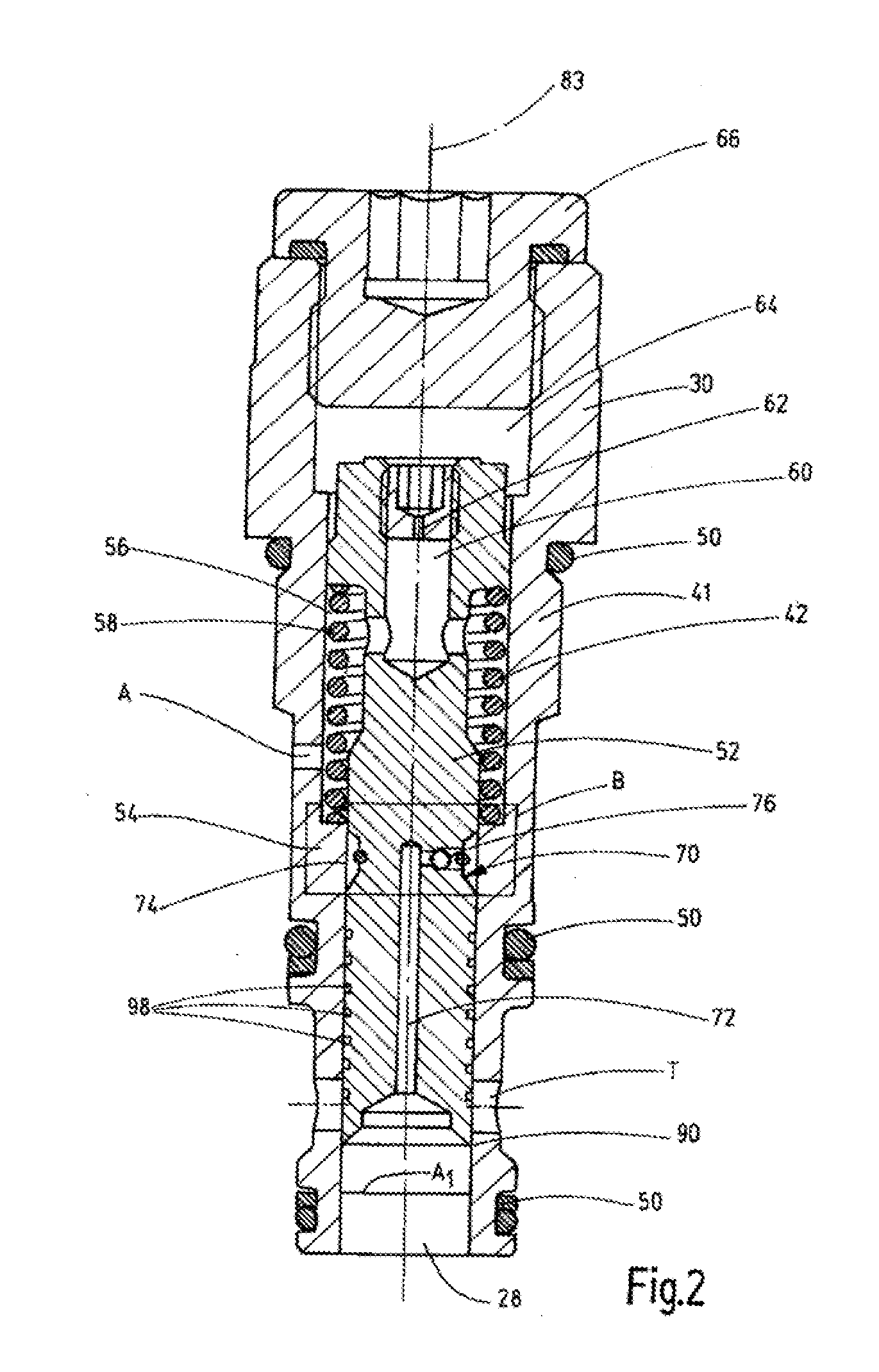
[0017] FIG. 2 shows the discharge pressure maintenance-type component according to the invention in the manner of a longitudinal sectional view; and
[0018] FIG. 3 shows an enlarged image detail, as shown in FIG. 2, having a box-shaped frame, designated by the letter B.
[0019] The hydraulic circuit diagram of FIG. 1 shows a hydraulic power cylinder 10, as it is regularly used for lifting and lowering applications, for instance in telehandlers, forklifts or lifting platforms. The power cylinder 10 has a longitudinally displaceable piston rod unit 14 in a housing 12, which unit divides the power cylinder 10 within the housing 12 into a piston chamber 16 and a rod chamber 18. A controllable motor pump unit, which lets fluid flow under pressure into the piston chamber 16, is used to extend the piston-rod unit 14 from the housing 12 of the power cylinder 10, for instance, for lifting a load. In this case, fluid is displaced via the rod chamber 18, which fluid is routed to a storage tank 20 via a suitable drain device. This type of control of power cylinders 10 for lifting-lowering applications is common in the prior art, i.e. will not be discussed in detail at this point.
[0020] Among other things, a proportional throttle valve 22, the inlet 24 of which is permanently connected to the piston chamber 16 of the power cylinder 10 in a fluid-conveying manner, is used to lower the piston-rod unit 14 in the housing 12. This proportional throttle valve 22 has an adjustable measuring orifice disk, which is common in the prior art. The outlet 26 of the valve 22 is in turn connected to the inlet 28 of a pressure maintenance-type component 30, which has a regulating orifice disk 32 in the usual way and which is also referred to as a discharge pressure maintenance-type component, because it regulates the flow of fluid from the piston chamber 16 of the power cylinder 10 upon lowering the piston rod unit 14. The discharge pressure maintenance-type component 30 has two opposite control sides 34, 36, as viewed in the direction of FIG. 1, the left control side 34 is connected to a connecting line 40 between the piston chamber 16 and the inlet 24 of the proportional throttle valve 22 via a control line 38 depicted as a dashed line. The load pressure of the power cylinder 10 is consequently transmitted via a connection port A in the valve housing 41 of the pressure maintenance-type component 30, which is also called the user port A. On the opposite right-hand control side 36, a compression spring 42 acts as an energy storage device and another control line 44 (shown as a dashed line), which transmits the control pressure 10 existing at the inlet 28 of the discharge pressure maintenance-type component 30 to the right control side 36. The outlet of the pressure maintenance-type component 30 forms the return port or tank port T, which leads to the storage tank 20.
[0021] The proportional throttle valve 22 shown in FIG. 1 using the usual switching symbol can be electromagnetically actuated via a control device 46 and held in its shown blocking position by a further pressure spring 48 as energy storage device.
[0022] Taken as a whole, to lower a load by means of the power cylinder 10, a proportional flow control function is implemented using the proportional throttle valve 22 and the discharge pressure maintenance-type component 30. For this purpose, the pressure maintenance-type component 30 takes over the task of keeping the pressure difference constant across the proportional throttle. Regardless of fluctuating load pressures or cylinder pressures, a constant volume flow is regulated in this way. To achieve a good quality of regulation, the pressure maintenance-type component 30 ideally routes the load pressure or cylinder pressure to the pressure-effective surface 36 of the regulating piston when the proportional throttle valve 22 is actuated via the further control line 44.
[0023] FIG. 1 shows the structure of a lifting-lowering device only in principle; of course, several cylinders 10 can be used for a lifting-lowering application having flow regulation devices for every cylinder 10 or using a joint flow regulation device for several cylinders 10. If the presented valve constellation having a proportional valve 22 and a pressure maintenance-type component 30 is to seal in a leak-free manner to prevent an unintentional lowering of the piston-rod unit 14 in the housing 12 of the power cylinder 10, it is provided in the prior art that the proportional throttle valve 22 terminates in a tightly sealed manner. However, a certain leakage flow, which results in an unwanted lowering of the piston-rod unit 14 during operation of the power cylinder 10 during lifting-lowering applications, nevertheless occurs via the mentioned load tap of the pressure maintenance-type component. The invention intends to remedy this, which will be explained in more detail below with reference to the valve structure of FIGS. 2 and 3. The previously introduced reference numerals together with the accompanying explanations are used accordingly, to the extent to which the same parts and components are meant, as explained above.
[0024] FIG. 2 as a whole shows the valve structure for the discharge pressure maintenance-type component 30. The valve housing 41 of the pressure maintenance-type component is designed in a stepped manner as shown in FIG. 2, such that the pressure maintenance-type component 30 can be used as a kind of insert or cartridge valve in assignable valve blocks or valve components (not shown). For sealing against these third structure components, sealing rings or sealing ring packages 50 are inserted on the outer circumference of the valve housing 41 in recesses provided for this purpose. As viewed in the direction of the FIG. 2 downwards, a cylindrical recess in the form of the inlet 28 of the pressure maintenance-type component 30 is introduced at the front side into the valve housing 41, which inlet is also referred to as control port 28. Arranged above it is the tank port or return port T, which consists of a plurality of mutually diametrically opposed drilled holes extending at the same height, which pass through the wall of the valve housing 41 in the radial direction. Above that, there is at least one (use) connection port A, which in turn is introduced into the valve housing 41 via a radial dilled hole. According to the illustration according to FIG. 1, the pressure is present behind the proportional valve 22 at the inlet 28 of the pressure maintenance-type component 30. The return port T is routed to the storage tank 20, which normally has tank or ambient pressure. The control connection port A is in turn connected to the piston chamber 16 of the power cylinder 10 in a permanently fluid-conveying manner via the control line 38 and the connecting line 40.
[0025] Within the valve housing 41 a regulating or valve piston 52 is guided longitudinally movably, which piston rests against the compression spring 42 as the one energy storage device according to the illustration of FIG. 2, wherein the other lower free end of this compression spring 42 rests against an inward projection 54 in the valve housing 41. The compression spring 42 is supported in a spring chamber 56 within the valve housing 41. This spring chamber 56 is connected in a fluid conveying manner to the connection port A in every position of the valve piston 52 and to an antechamber 60 at the upper end via a transverse connection 58 in the form of radial drilled holes in the valve piston 52, which antechamber opens in turn via a damping device 62 in the form of an orifice disk or throttle into a damping chamber 64 in the interior of the valve housing 41. This damping chamber 64 is closed at the top in a sealing manner by a closing part 66, which can be screwed into the interior of the valve housing 41 there. The damping device 62 is designed as a screw-in part in the valve piston 52, wherein the respective screw can have different throttle or orifice disk diameters, such that the intended valve damping can be adapted to a variety of such valve designs for a discharge pressure maintenance-type component 30 in an obvious manner.
[0026] Furthermore, the pressure maintenance-type component 30 according to the invention is provided with a pressure compensation device designated as a whole by the numeral 70. This pressure compensation device 70 has a pressure compensation channel 72, the one free, lower end of which is centrally guided at the lower end of the valve piston 52 in the direction of the connection port or the valve inlet 28 and the other free end of which opens in an annular channel 74, which is introduced in the valve piston 52 at the outer peripheral side. The pressure compensation channel 72 in the form of the centrally disposed longitudinal drilled hole in the valve piston 52 further comprises a transverse drilled hole 76 as a transverse channel, which in turn opens in the mentioned annular channel 74 as part of the channel 72. In this case, a valve ball 78 is inserted in the transverse channel or the transverse drilled hole 76, which ball acts in the manner of a check valve and in a traversing movement, viewed in the direction of FIGS. 2 and 3, from left to right opens a channel cross-section in the transverse drilled hole 76, such that in the opening or open position, a first throttled fluid-conveying connection between the pressure equalizing channel 72 and the annular channel 74 is established. For this purpose, the diameter of the transverse drilled hole 76 outside the range of the seat system 80 of the valve ball 78 on the valve piston 52 is widened, in particular provided with a larger diameter than the valve ball 78. To prevent the valve ball 78 from unintentionally leaving the transverse drilled hole 76, its position is secured within the transverse drilled hole 76 by a retaining ring 82, which may be formed of a metallic locking ring, which to that extent encompasses the valve piston 52 in the horizontal plane shown transversely to the longitudinal or longitudinal axis 83 of the valve partially guided in a corresponding recess. This locking ring can safely counteract the expelling compressive forces acting on the ball 78. These conditions are evident from an improved representation from FIG. 3, which relates to an enlarged view of the rectangular section in FIG. 2 designated B.
[0027] As further shown in particular in FIG. 3, the annular channel 74, as viewed in the cross section shown, has a rectilinear groove bottom 84, which extends in parallel to the longitudinal axis 83 of the pressure maintenance-type component 30 and into which the transverse drilled hole 76 opens and against which the retaining ring 82 abuts, and, starting from this groove bottom 84, the annular channel 74 has a convex course 86 at its upper end and at its opposite lower end opens via a gradient 88 having a constant gradient onto the outer peripheral side of the valve piston 52. It has been found that this cross-sectional profile for the annular channel 74 is particularly suitable for the desired control of the valve piston 52, as will be explained in more detail below.
[0028] Viewed in the direction of FIG. 2, the valve piston 52 has a cylindrical circumferential control edge 90 at its lower end, which edge is used to regulate the fluid between the two ports 28 and T, as soon as the pressure maintenance-type component 30 is in one of its "opened" control positions. This control edge 90 forms the regulating orifice disk with the associated radial drilled holes at the port T in the valve body 30. However, in the position shown in FIG. 2, the underside of the valve piston 52 closes this return port or tank port T. Starting from said control edge 90, the valve piston 52 tapers inwardly to a transition point where the pressure compensation channel 72 exits in the direction of the inlet 28 of the pressure maintenance-type component 30. The pressure compensation channel 72 including its transverse drilled hole 76 and annular channel 74 forms the other control line 44 as shown in FIG. 1.
[0029] As is further evident in particular from FIG. 3, an obliquely extending seat surface 92 in the valve housing 41 is additionally arranged below the projection 54 in the interior of the valve housing 41 as a contact surface for the lower end of the compression spring 42. Instead of a gradient, the shape of the seat 92 can assume all known valve seat geometries, such as spherical cap, cone, etc. The resulting surface difference results in every type of sealing geometry described above, in which initially a line contact between the two components develops, for the formation of a tightly sealing leak-free valve seat 94, the valve piston 52, at a point of widened diameter, additionally has a contact surface 96, which has a correspondingly inclined design. The seat 42 on the sides of the valve housing 41 is formed larger than the correspondingly arranged inclined contact surface 96 of the valve piston 52, such that it can always easily reach a stop position with the valve housing 41. During operation of the valve, the permanent "abutment" of the valve piston 52 against the valve housing 41 in the region of the valve seat 94 results in irregular impressions on this valve seat 94 which, in conventional pressure maintenance-type component structures, would result in such pressure conditions on the valve piston 52 that it would no longer easily open against the action of the compression spring 42, as will be explained in more detail below.
[0030] In FIGS. 2 and 3, the valve piston 52 is shown in its closed position, in which the lower end of the piston 52 completely covers the tank port or return port T. In this closed position, the convex course 86 of the annular channel 74 opens into the rectilinear contact surface 96 on the valve piston 52 upstream of any possible irregular impressions. The valve seat 94, in particular having a seat surface 92 at the valve housing 41 enlarged beyond the contact surface 96, permits the valve piston 52, after a large number of regulating and closed positions, to find its own "snug fit" at the associated irregular impressions on the seat surface 92 at the valve housing 41. For the purpose of precisely guiding the valve piston 52 in the valve housing 41, it is guided on the outer circumference by correspondingly long guide paths on the inner wall of the valve housing. In particular, the annular grooves 98 introduced in the lower third of the valve piston 52 permit a functionally reliable sealing of the annular channel 74 acted upon by pressure medium against the pressure at the control inlet 28 of the discharge pressure maintenance-type component 30, which is provided by the proportional throttle valve 22 on the outlet side.
[0031] Based on pressure-effective surfaces A.sub.1, A.sub.2 and A.sub.1* the operation of the pressure maintenance-type component 30 according to the invention for performing an opening or regulation operation will now be explained in more detail.
[0032] The surface A.sub.1 at the control inlet 28 of the pressure maintenance-type component 30 (FIG. 2) is delimited by the cylindrical inner wall of the valve housing 41 in the region of the inlet 28 and the surface A.sub.1 forms the free flow cross section for the inflowing fluid at the inlet 28 of the pressure maintenance-type component 30. The surface A.sub.2 shown in FIG. 3 is formed by the diameter, which results from the impressed annular contact surface as soon as the valve piston 52 assumes its individually impressed valve seat 94. The surface underneath in FIG. 3 A.sub.1* is again formed by the cross-section, which results at the transition point between the convex course 86 of the annular channel 74 and the contact surface 96 at the valve piston 52.
[0033] If the adjustable measuring orifice disc or the proportional throttle valve 22 is opened to allow a volume flow in the direction of the control inlet 28 of the pressure maintenance-type component 30, the same pressure, namely p=p.sub.load, is present at both two faces A.sub.1 and A.sub.2, the load pressure p.sub.load resulting from the pressure in the piston chamber 16 of every power cylinder 10 connected to the valve assembly described. In that regard, this load pressure p.sub.load in the piston chamber 16 is not only transmitted to the inlet 28 of the pressure maintenance-type component 30 upon the appropriate actuation of the throttle valve 22, but also transmitted to the (use) port A via the first control line 38 (FIG. 1) thus acting on the valve piston 52 in the opposite direction from the pressure at the inlet 28. As a result of the described irregular impressions or the geometric design of the described valve seat 94, from a structural point of view the surface A.sub.2 is always larger than the surface A.sub.1. From this surface difference a closing force component follows that prevents an opening of the valve in the form of the discharge pressure maintenance-type component 30 against the comparatively low spring force of the compression spring 42, wherein the spring force of the compression spring 42 always acts in the opening direction of the valve piston 52, in which it moves upwards viewed in direction of FIG. 2 to allow a regulating fluid connection between the control inlet 28 and the tank port or return port T by means of the control edge 90.
[0034] The pressure compensation channel 72 in the valve piston 52 of the pressure compensation device 70 now permits simultaneously a pressure message of p=p.sub.load to the surface A.sub.1*, which has the same design as the surface A.sub.2. Thus, the regulating or valve piston 52 is then pressure compensated and the pressure maintenance-type component 30 can be opened when the throttle valve 22 opens solely due to the spring force of the energy storage device, i.e. the compression spring 42. The check valve having the ball valve 78 provided within the pressure compensation device 70 prevents leakage, starting from port A in the direction of the inlet port 28 in the control position of the pressure maintenance-type component 30. Here, the pressure in the annular channel 74 is always higher than the pressure at the inlet 28, i.e. the check valve can always be kept tightly sealed.
[0035] In relation to the damping device 62, the damping or the displacement of the medium occurs via a hydraulic resistance and always via the combination of the orifice disk and the annular gap, which is formed between the piston and the valve body. This results in the following damping solutions: closed orifice disk; the media flows exclusively via the annular gap or, for a variable orifice disk diameter, a media flow results via orifice disk and annular gap.
[0036] The solution according to the invention has provided a discharge pressure maintenance-type component 30, which seals in the end position shown in FIGS. 2 and 3 against the valve seat 94 without leakage and yet for an attached hydraulic load, for instance according to the exemplary embodiment of FIG. 1, can implement a pressure compensation, as described above, at the valve seat 94 to ensure the control function of the discharge pressure maintenance-type component 30. This is without parallel in the prior art.
* * * * *
D00000
D00001
D00002
XML
uspto.report is an independent third-party trademark research tool that is not affiliated, endorsed, or sponsored by the United States Patent and Trademark Office (USPTO) or any other governmental organization. The information provided by uspto.report is based on publicly available data at the time of writing and is intended for informational purposes only.
While we strive to provide accurate and up-to-date information, we do not guarantee the accuracy, completeness, reliability, or suitability of the information displayed on this site. The use of this site is at your own risk. Any reliance you place on such information is therefore strictly at your own risk.
All official trademark data, including owner information, should be verified by visiting the official USPTO website at www.uspto.gov. This site is not intended to replace professional legal advice and should not be used as a substitute for consulting with a legal professional who is knowledgeable about trademark law.