Anti-pinch Control System For Powered Vehicle Doors
Khan; Muhammad Omer ; et al.
U.S. patent application number 16/395612 was filed with the patent office on 2019-08-15 for anti-pinch control system for powered vehicle doors. This patent application is currently assigned to Ford Global Technologies, LLC. The applicant listed for this patent is Ford Global Technologies, LLC. Invention is credited to George Anthony Bernwanger, JR., Muhammad Omer Khan, H. Paul Tsvi Linden, Kosta Papanikolaou, Christopher Matthew Radjewski.
| Application Number | 20190249475 16/395612 |
| Document ID | / |
| Family ID | 60020815 |
| Filed Date | 2019-08-15 |


View All Diagrams
| United States Patent Application | 20190249475 |
| Kind Code | A1 |
| Khan; Muhammad Omer ; et al. | August 15, 2019 |
ANTI-PINCH CONTROL SYSTEM FOR POWERED VEHICLE DOORS
Abstract
A vehicle includes a body and front and rear doors having front and rear powered latches, front and rear anti-pinch sensors, and front and rear electrically-powered door openers. The vehicle further includes a controller that is configured to receive an unlatch signal from unlatch sensors/switches and generate a signal to unlatch the front and rear powered latches and actuate the front and rear door openers after the front and rear powered latches are unlatched. The controller may also be configured to actuate the rear door opener to retain the rear door in an open position when the front pinch sensor detects a hand to thereby prevent pinching.
| Inventors: | Khan; Muhammad Omer; (Markham, CA) ; Papanikolaou; Kosta; (Huntington Woods, MI) ; Radjewski; Christopher Matthew; (Macomb, MI) ; Linden; H. Paul Tsvi; (Southfield, MI) ; Bernwanger, JR.; George Anthony; (Northville, MI) | ||||||||||
| Applicant: |
|
||||||||||
|---|---|---|---|---|---|---|---|---|---|---|---|
| Assignee: | Ford Global Technologies,
LLC Dearborn MI |
||||||||||
| Family ID: | 60020815 | ||||||||||
| Appl. No.: | 16/395612 | ||||||||||
| Filed: | April 26, 2019 |
Related U.S. Patent Documents
| Application Number | Filing Date | Patent Number | ||
|---|---|---|---|---|
| 15245622 | Aug 24, 2016 | 10329823 | ||
| 16395612 | ||||
| Current U.S. Class: | 1/1 |
| Current CPC Class: | E05F 15/46 20150115; E05Y 2201/426 20130101; E05Y 2400/44 20130101; E05F 15/44 20150115; E05F 15/43 20150115; E05Y 2201/232 20130101; E05F 5/00 20130101; E05F 15/60 20150115; E05F 15/611 20150115; E05F 15/42 20150115; B60J 5/047 20130101; E05Y 2201/22 20130101; E05Y 2400/54 20130101; E05Y 2201/40 20130101; E05Y 2900/531 20130101; E05Y 2800/41 20130101; E05Y 2400/20 20130101 |
| International Class: | E05F 15/42 20060101 E05F015/42; E05F 15/46 20060101 E05F015/46; B60J 5/04 20060101 B60J005/04; E05F 15/611 20060101 E05F015/611; E05F 15/44 20060101 E05F015/44; E05F 5/00 20060101 E05F005/00; E05F 15/60 20060101 E05F015/60 |
Claims
1. A vehicle comprising: a body and front and rear doors having front and rear: a) powered latches; b) unlatch switches; c) anti-pinch sensors; and d) electrically-powered door openers; a controller configured to: receive unlatch signals and unlatch the respective front and rear powered latches and actuate the front and rear door openers; and: actuate the rear door opener to retain the rear door in an open position when the front anti-pinch sensor detects a hand.
2. The vehicle of claim 1, wherein: the front and rear electrically-powered door openers include plungers that shift from retracted positions to extended positions to push the doors open.
3. The vehicle of claim 2, wherein: the body includes front and rear strikers; the front and rear powered latches each include a rotating claw that is configured to engage a striker on the body, and an electrically-powered actuator that shifts a pawl between a latched position in which the pawl prevents rotation of the rotating claw, and an unlatched position in which the rotating claw can rotate and disengage from a striker, and wherein: the controller resets the front and rear powered latches to permit latching when the controller determines that the front and rear doors, respectively, are in a fully open position.
4. The vehicle of claim 2, wherein: the front and rear powered latches comprise electrically-powered cinching latches that are configured to shift the front and rear doors to fully closed positions; the controller is configured to prevent cinching of the front and rear powered latches when the front and rear anti-pinch sensors, respectively, detect a user's hand.
5. A vehicle, comprising: a body having adjacent front and rear door openings; front and rear doors rotatably mounted to the body to close off the front and rear door openings, respectively, when the doors are in closed positions; front and rear anti-pinch sensors that are configured to detect user's hands adjacent the front and rear door openings, respectively: front and rear electrically-powered latch mechanisms that are configured to permit the front and rear doors, respectively to open when the electrically-powered latch mechanisms are unlatched, and retain the front and rear doors in closed positions when the electrically-powered latch mechanisms are latched; front and rear electrically-powered door actuators that can be actuated to shift the front and rear doors, respectively, from closed positions to open positions; a controller configured to actuate at least one of the front and rear electrically-powered door actuators to prevent the at least one of the front and rear doors from closing if at least one of the front and rear anti-pinch sensors detects a user's hand.
6. The vehicle of claim 5, wherein: the controller is configured to actuate the rear electrically-powered door actuator to retain the rear door in an open position if the front anti-pinch sensor detects a hand.
7. The vehicle of claim 5, wherein: the open positions comprise first partially open positions; the front and rear electrically-powered door actuators can be actuated to shift the front and rear doors, respectively, to second partially open positions in which the front and rear doors are further open than in the first partially open positions.
8. The vehicle of claim 7, wherein: the front and rear electrically-powered door actuators each include a plunger that shifts from a retracted position to first and second extended positions to push the front and rear doors from closed positions to first and second partially open positions, respectively; the controller is configured to cause the plungers to stop at the first extended position only if predefined operation conditions are present.
9. The vehicle of claim 8, wherein: the controller is configured to retract the plungers of the front and rear electrically-powered door actuators to retracted positions when the front and rear doors, respectively are open only if the front and rear anti-pinch sensors, respectively, do not detect a user's hand.
10. The vehicle of claim 9, wherein: the controller is configured to reset the front and rear electrically-powered latch mechanisms to enable the front and rear electrically-powered latch mechanisms to latch when the controller detects that the plunger has shifted to the second extended position.
Description
CROSS-REFERENCE TO RELATED APPLICATION
[0001] This application is a divisional of U.S. patent application Ser. No. 15/245,622, filed Aug. 24, 2016, and entitled "ANTI-PINCH CONTROL SYSTEM FOR POWERED VEHICLE DOORS," the entire disclosure of which is hereby incorporated herein by reference.
FIELD OF THE INVENTION
[0002] The present invention generally relates to vehicle doors, and in particular to a vehicle including one or more powered door opening mechanisms and anti-pinch sensors to prevent pinching of user's hands.
BACKGROUND OF THE INVENTION
[0003] Various types of vehicle doors and door latch mechanisms have been developed. The vehicle doors may have powered door opening mechanisms. Known vehicle doors may also include powered latches that can be actuated to permit opening a vehicle door without requiring movement of an external door handle. However, known vehicle door systems may suffer from various drawbacks.
SUMMARY OF THE INVENTION
[0004] One aspect of the present disclosure is a vehicle door system including a vehicle structure having a door opening and a door that is rotatably mounted to the vehicle structure to close off the door opening when the door is in a closed position. The vehicle door system also includes an anti-pinch sensor that is configured to detect a user's hand if a user's hand is positioned adjacent the door opening. An electrically-powered latch mechanism permits the door to open when the electrically-powered latch mechanism is unlatched. The electrically-powered latch mechanism retains the door in a closed position when the electrically-powered latch mechanism is latched. The door system further includes an electrically-powered door actuator that can be actuated to shift the door from a closed position to a partially open position. The vehicle door system further includes a controller that is configured to actuate the electrically powered door actuator to prevent the door from closing if the anti-pinch sensor detects a user's hand.
[0005] Another aspect of the present disclosure is a vehicle including a body and front and rear doors having, respectively, front and rear powered latches, front and rear pinch sensors, and front and rear electrically-powered door openers. The vehicle further includes a controller that is configured to receive an unlatch signal and unlatch the front and rear powered latches and actuate the front and rear door openers and actuate the rear door opener to retain the rear door in an open position when the front pinch sensor detects a user's hand.
[0006] Another aspect of the present disclosure is a vehicle door system including a vehicle structure having adjacent front and rear door openings. Front and rear doors are rotatably mounted to the vehicle structure to close off the front and rear door openings, respectively, when the doors are in closed positions. Front and rear anti-pinch sensors that are configured to detect user's hands adjacent the front and rear door openings, respectively. Front and rear electrically-powered latch mechanisms are configured to permit the front and rear doors, respectively, to open when the electrically-powered latch mechanisms are unlatched. The front and rear electrically-powered latch mechanisms retain the front and rear doors in closed positions when the electrically-powered latch mechanisms are latched. The vehicle door system also includes front and rear electrically-powered door actuators that can be actuated to shift the front and rear doors, respectively, from closed positions to open positions. A controller is configured to actuate at least one of the front and rear electrically-powered door actuators to prevent the at least one of the front and rear doors from closing if at least one of the front and rear anti-pinch sensors detects a user's hand.
[0007] These and other aspects, objects, and features of the present invention will be understood and appreciated by those skilled in the art upon studying the following specification, claims, and appended drawings.
BRIEF DESCRIPTION OF THE DRAWINGS
[0008] In the drawings:
[0009] FIG. 1 is a partially schematic plan view of a vehicle including anti-pinch sensors and powered door actuators that open the vehicle doors;
[0010] FIG. 2 is a schematic view of a portion of the vehicle of FIG. 1;
[0011] FIG. 3 is a schematic view of a portion of the vehicle of FIG. 1;
[0012] FIG. 4 is a schematic view of a powered door actuator in a first check position;
[0013] FIG. 5 is a schematic view of a powered door actuator in a second check position;
[0014] FIG. 6 is a schematic plan view of a vehicle door in a closed position;
[0015] FIG. 7 is a schematic plan view of a vehicle door in a partially open position;
[0016] FIG. 8 is a schematic plan view of a vehicle door in a fully open position;
[0017] FIG. 9 is a flow chart showing operation of a vehicle including a power release latch and powered door opening actuator with locally controlled anti-pinch door sensors;
[0018] FIG. 10A is a first portion of a flow chart showing operation of a vehicle door system that includes front and rear doors having powered door latches, powered door opening mechanisms and front and rear anti-pinch door sensors;
[0019] FIG. 10B is a second portion of the flow chart of FIG. 10A; and rear doors having powered door latches, powered door opening mechanisms and front and rear anti-pinch door sensors;
[0020] FIG. 11A is a first portion of a flow chart showing vehicle door operation for doors including powered door latches, powered door opening actuators, front and rear anti-pinch sensors, and front and rear door position sensors;
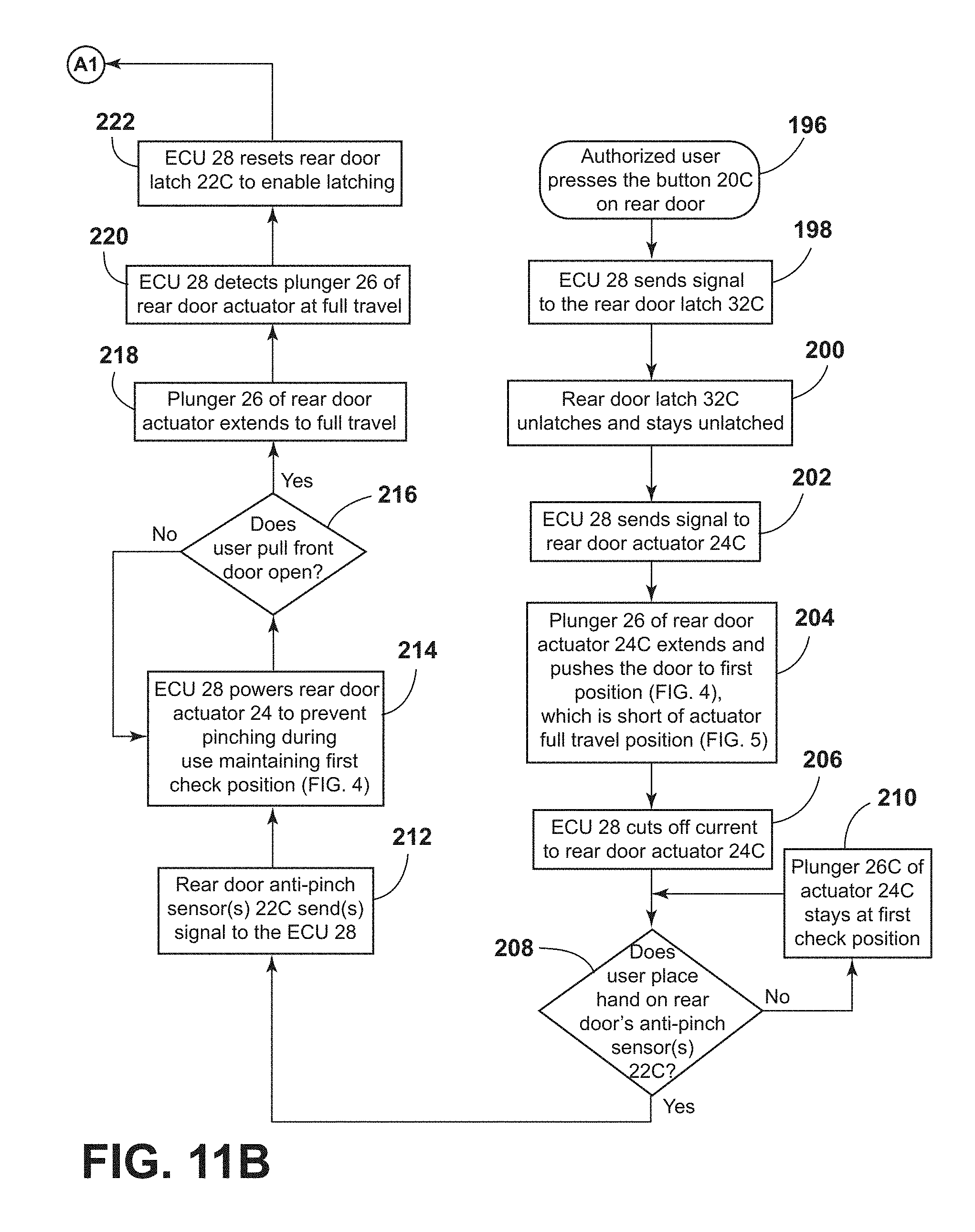
[0021] FIG. 11B is a second portion of the flow chart of FIG. 11A;
[0022] FIG. 12A is a first portion of a flow chart for a door system including powered front and rear door latches, powered front and rear door opening mechanisms, and front and rear anti-pinch door sensors;
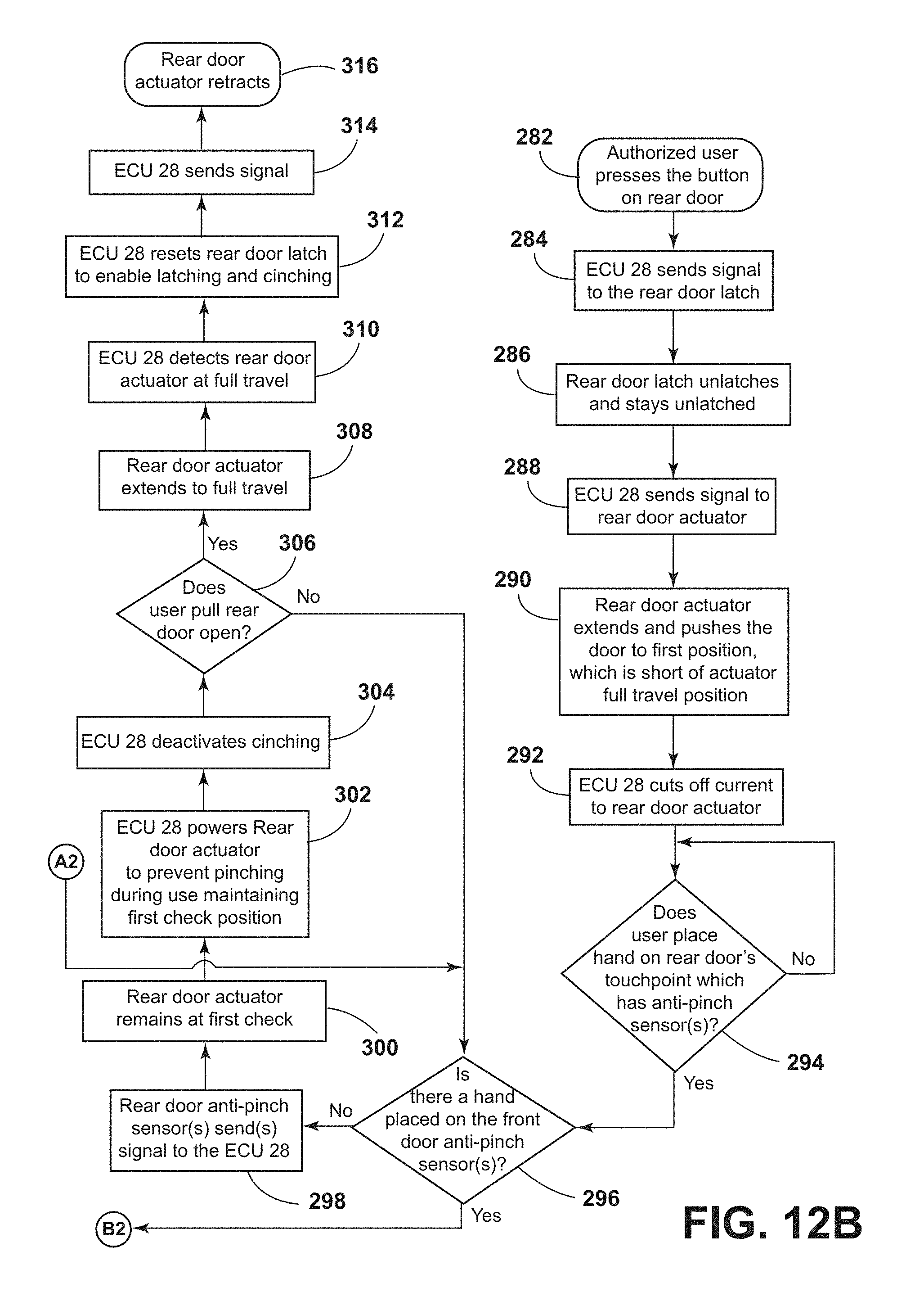
[0023] FIG. 12B is a second portion of the flow chart of FIG. 12A;
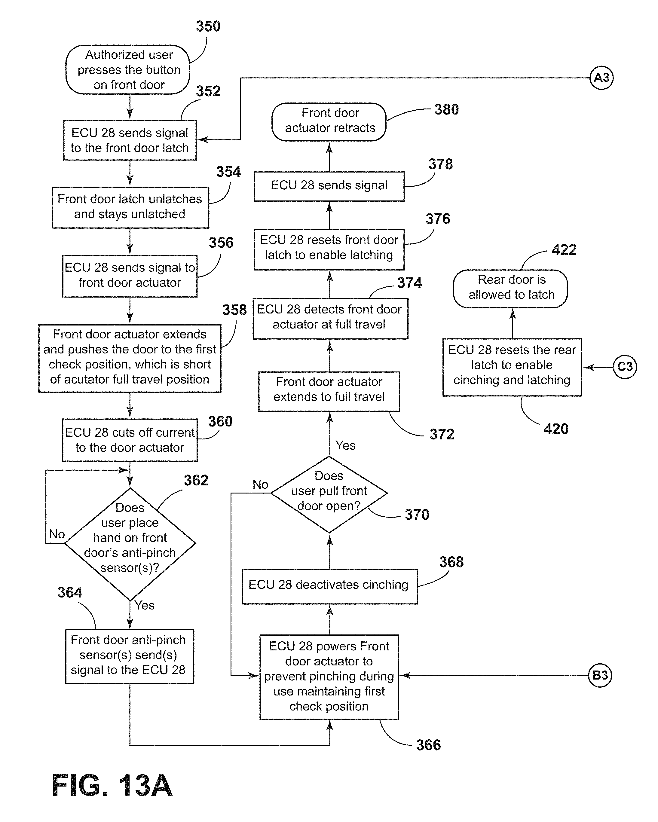
[0024] FIG. 13A is a first portion of a flow chart showing operation of a vehicle door system including powered cinching front and rear door latches, powered front and rear door opening actuators, front and rear anti-pinch sensors, and front and rear door position sensors; and
[0025] FIG. 13B is a second portion of the flow chart of FIG. 13A.
DETAILED DESCRIPTION OF THE PREFERRED EMBODIMENTS
[0026] For purposes of description herein, the terms "upper," "lower," "right," "left," "rear," "front," "vertical," "horizontal," and derivatives thereof shall relate to the invention as oriented in FIG. 1. However, it is to be understood that the invention may assume various alternative orientations and step sequences, except where expressly specified to the contrary. It is also to be understood that the specific devices and processes illustrated in the attached drawings, and described in the following specification are simply exemplary embodiments of the inventive concepts defined in the appended claims. Hence, specific dimensions and other physical charac-teristics relating to the embodiments disclosed herein are not to be considered as limiting, unless the claims expressly state otherwise.
[0027] With reference to FIG. 1, a motor vehicle 1 includes a body structure 2, front doors 4A and 4B, and rear doors 6A and 6B. The front doors 4A and 4B are configured to open and close to provide access to interior 12 of vehicle 1 through front openings 10A and 10B, respectively. Similarly, rear doors 6A and 6B are configured to open and close to provide access through rear door openings 14A and 14B. Front doors 4A and 4B are rotatably mounted to body structure 2 by hinges 16A and 16B, and rear doors 6A and 6B are rotatably mounted to body structure 2 by rear hinges 18A and 18B, respectively. As discussed in more detail below, the vehicle doors 4A, 4B, 6A and 6B may include exterior switches or sensors 20A-20B, respectively that can be actuated by a user to unlatch and open the vehicle doors. Vehicle 1 may comprise a two door vehicle having only front doors 4A and 4B, and front openings 10A and 10B.
[0028] Vehicle 1 further includes anti-pinch sensors 22A-22D that are configured to detect a user's hand if the user's hand is inserted into an opening 10A, 10B, 14A, 14B when a vehicle door is opened. Pinch sensors 22A-22D may comprise capacitive sensors, pressure sensitive sensors, or other suitable sensor capable of detecting a user's hand. Pinch sensors 22A-22D may be mounted to the body structure 2 adjacent the door openings. Vehicle door 4A also includes a powered door opener 24 that includes a plunger 26 that can be shifted to a first extended position to partially open the door 4A (see also FIG. 7). The doors 4B, 6A, and 6B may also include powered door opening mechanisms 24. The doors 4A, 4B, 6A, and 6B also include powered latch mechanisms 32A-32D. The powered latches 32A-32D can be actuated by controller 28 to unlatch the doors if unlatch switches 20A-20D, respectively, are actuated by a user. The controller 28 may be operably connected to the anti-pinch sensors 22A-22D, powered door opening mechanisms 24A-24D, and powered latches 32A-32D. Controller 28 may comprise a single central controller as shown in FIG. 1, or controller 28 may comprise separate controllers that are located in each door 4A, 4B, 6A, and 6B. The powered door opening mechanisms 24A-24D and powered latches 32A-32D are described in more detail in copending U.S. Pat. No. 10,227,810, issued on Mar. 12, 2019, entitled "PRIORITY DRIVEN POWER SIDE DOOR OPEN/CLOSE OPERATIONS," the entire contents of which are incorporated herein by reference. As discussed in the above-referenced '672 patent application, powered latches 32A-32D may include a rotating claw that engages a striker on body structure 2 to retain doors 4A, 4B, 6A and 6B in closed positions. A movably pawl engages the claw to prevent rotation of the claw when powered latches 32A-32D are latched. Conversely, the pawl permits rotation of the claw when latches 32A-32D are unlatched. An electrically-powered actuator is operably connected to the pawl and shifts the pawl between engaged (latched), and disengaged (unlatched) positions when electrical power is supplied to the powered actuator by controller 28.
[0029] As discussed in more detail below, to enter vehicle 1 a user pushes release switch 20A which is operably connected to a controller or electric control unit ("ECU") 28. It will be understood that controller 28 may comprise various hardware and/or software, and the terms "controller" and "ECU" are not limited to any specific device and/or software. Controller 28 then actuates the powered door opening mechanism 24 to thereby cause the plunger 26 to shift to an extended ("first check") position to thereby at least partially open door 4A whereby rear edge 30A of door 4A is spaced apart from vehicle body 2. A user then grasps edge 30A and pulls door 4A to a fully open position. The other doors 4B, 6A, and 6B may be opened in a substantially similar manner.
[0030] The powered door opening mechanism 24 permits elimination of external vehicle door handles that would otherwise be required to permit a user to grasp the door handle to pull the door open.
[0031] Opening and closing of the driver's side front and rear doors 4A and 6A is shown schematically in FIGS. 2 and 3. It will be understood that the passenger side doors 4B and 6B operate in a substantially similar manner as driver's side doors 4A and 6A. As discussed below in connection with FIGS. 4-8, in use, a user initially actuates a sensor or switch 20A or 20C to generate an unlatch request to controller 28. For example, if a user pushes the unlatch switch 20A, controller 28 generates a signal to powered latch 32A of front door 4A to thereby provide powered unlatching of latch 32A. Similarly, if unlatch switch 20C is actuated, controller 28 generates a signal to unlatch powered latch 32C of rear door 6A. After the powered latch is unlatched, controller 28 then generates a signal to the powered actuator 24A or 24C, causing plunger 26 to extend and push door 4A or 6A to a partially opened position. A user then grasps rear edge 30A or 30C of door 4A or 6A to pull the door to a fully open position. As a user grasps the edge 30A or 30C, anti-pinch sensors 22A or 22C generate a signal to controller 28 indicating that a user's hand is present. Controller 28 may then generate a signal to retain the plunger 26 in an extended position to prevent pinching of a user's hand.
[0032] Referring to FIG. 3, when rear door 6A is opened and front door 4A remains closed, a user may nevertheless insert a hand and grasp rear edge 30A of front door 4A even though front door 4A is in a closed position. If rear door 6A were to be closed this could pinch a user's hand positioned adjacent front pinch sensor 22A. As discussed in more detail below in connection with FIGS. 10A, 10B, 11A, 11B, 12A, 12B, 13A, and 13B, controller 28 is configured/programmed to prevent pinching if the front door 4A is closed while the rear door 6A is open as shown in FIG. 3. As shown in FIG. 3, anti-pinch sensors 122A, 122C, etc. may optionally be mounted to the vehicle doors 4A, 6A adjacent the rear edges 30A, 30C, etc.
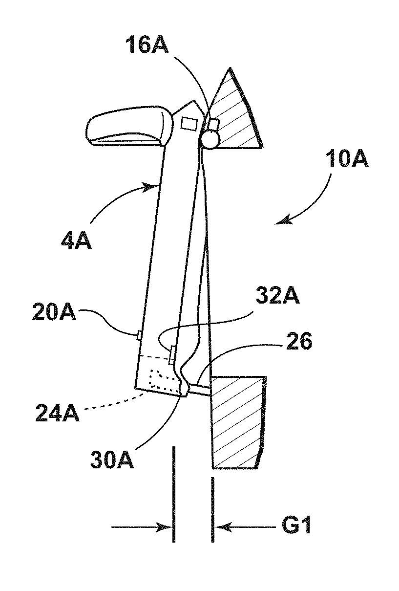
[0033] With further reference to FIGS. 4 and 5, an electrically-powered door opening mechanism 24A is disposed in an interior space 34A of door 4A between outer side 36A and inner side 38A of door 4A. All doors of the vehicle 1 may include powered door opening mechanisms that are substantially similar to the mechanism 24A. Mechanism 24A may include a housing or base structure 46 and a plunger 26 that is movably interconnected with the housing 46 for reciprocating movement relative to the housing 46. The mechanism 24A may include an electric motor 40 and gear drive 42 that provide for powered movement of plunger 26. A sensor 44 enables controller 28 to determine the position of plunger 26 relative to housing 46. The components of powered actuator 24A are shown schematically in FIGS. 4 and 5. It will be understood that the powered door opening mechanism 24A may have various configurations as required for a particular application. For example, the powered door opening mechanism 24 may be configured as disclosed in copending U.S. Pat. No. 10,227,810, issued on Mar. 12, 2019, 2016, entitled "PRIORITY DRIVEN POWER SIDE DOOR OPEN/CLOSE OPERATIONS."
[0034] Plunger 26 may be actuated to extend to a first check position 26A (FIG. 4) in which plunger 26 extends a distance "P1," causing door 4A to open to a first partially open position (see also FIG. 7) whereby a gap "G1" is formed between inner surface 38A of door 4A and surface 50 of vehicle body 2. A pad or surface 48 may be disposed on surface 50 of body 2 in the region where plunger 26 contacts surface 50 of vehicle body 2. As also discussed below, the plunger 26 may be further extended to a fully extended position "P2" that is slightly greater than distance P1 as shown in FIG. 5. Plunger 26 shifts to fully extended position P2 after door 4A has been shifted to a fully open position (e.g. pulled open by a user). Controller 28 may be configured to detect travel of plunger 26 to fully extended position P2, and utilize the P2 position as an indication that the door has been shifted to a fully open position. Alternatively, door hinges 16A, 18A, etc. may include a sensor (not shown) that detects the angular positions of the doors such that controller 28 can determine when the doors are fully open. The second check position P2 and/or rotation sensors are optional, and controller 28 may be configured to operate without a sensor input indicating that a vehicle door has been fully opened. In general, the distance P1 (and gap G1) may be about one to about four inches. The second distance P2 may be, for example, 0.25 inches, 0.50 inches (or more) greater than distance P1.
[0035] With further reference to FIGS. 6-8, a user initially actuates switch or sensor 20A when door 4A is in a closed position (FIG. 6). Controller 28 then unlatches the powered latch 32A, and actuates powered door opener 24A to extend plunger 26 to a first check (distance P1) position in which door 4A is in a first partially opened position creating a gap G1 as shown in FIG. 7. A user then grasps edge 30A of door 4A and pulls the door to a fully open position shown in FIG. 8. As discussed below, the plunger 26 is retracted while the door 4A is in a fully open position (FIG. 8), and the powered latch 32A is then reset. A user can then push the door 4A from the open position (FIG. 8) to the closed position (FIG. 6), and powered latch 32A retains the door 4A in the fully closed position (FIG. 6). Powered latch 32A may comprise a cinching door latch. For example, the claw 180 of the powered latch described in the U.S. Pat. No. 10,227,810 may be operably connected to a powered actuator (e.g. electric motor) whereby the claw rotates from an open/released position to a latched/closed position to engage a striker to pull the door to a fully-closed position. If the powered latch 32A is a cinching door latch, door 4A may be initially pushed to a mostly closed position 52 (FIG. 8), and the powered latch 32A may then be actuated to shift the door to the fully closed position of FIG. 6. Cinching latch mechanisms are disclosed in U.S. Pat. No. 9,004,570, issued on Apr. 14, 2015 and entitled "ADJUSTABLE LATCH ASSEMBLY" and U.S. Pat. No. 9,951,547, issued on Apr. 24, 2018 and entitled "ADJUSTABLE DECKLID LATCH ASSEMBLY" the entire contents of each being incorporated herein by reference. Cinching door latches are generally known in the art, and a detailed description of a cinching door latch is therefore not believed to be necessary. It will be understood that all of the doors 4A, 4B, 6A, and 6B of vehicle 1 may operate in substantially the same manner as the doors shown and described above in connection with FIGS. 2-8.
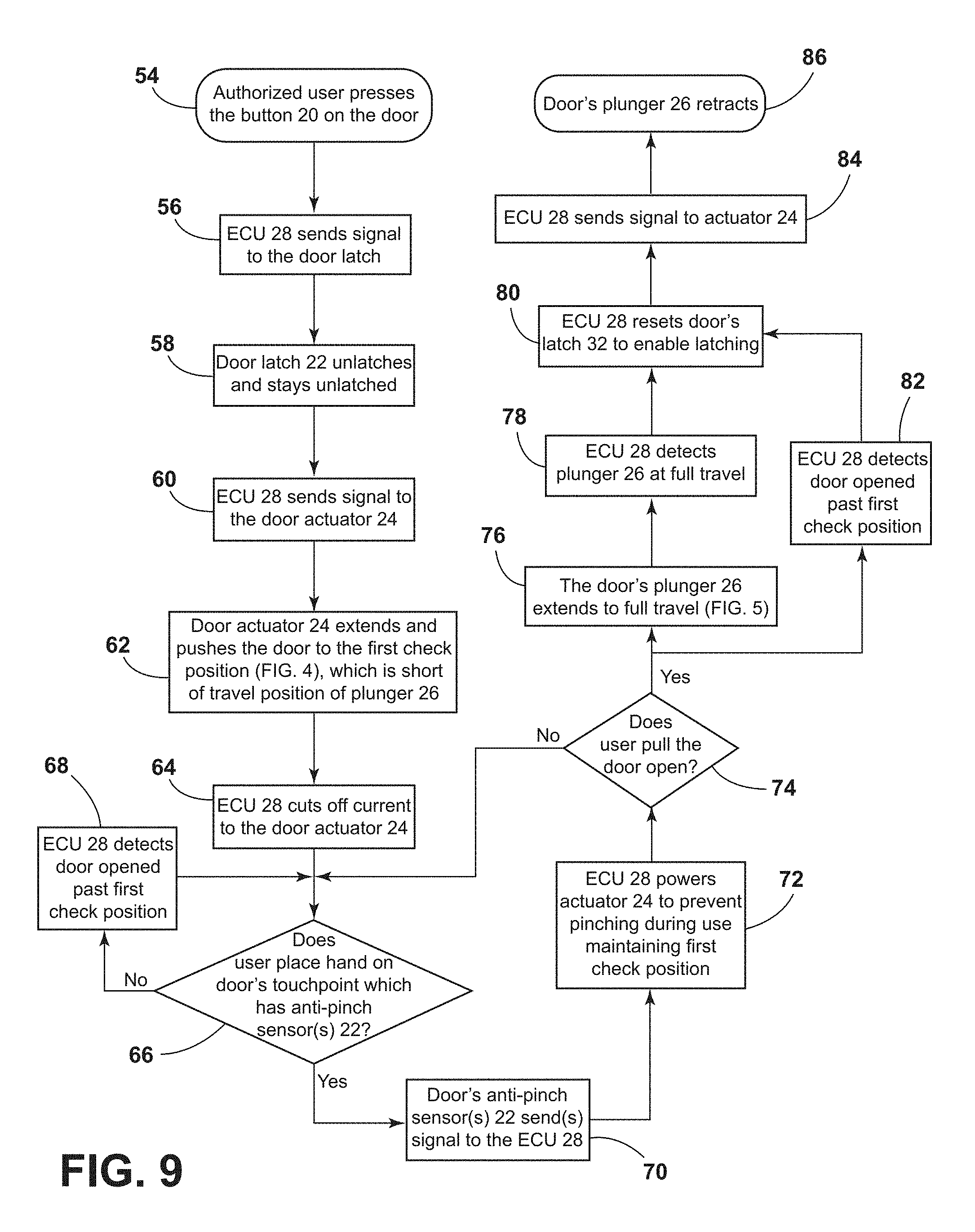
[0036] Operation of a single vehicle door having a locally controlled anti-pinch door sensor is shown in the flow chart of FIG. 9. The control arrangement of FIG. 9 may be utilized if, for example, vehicle 1 includes only front doors 4A and 4B, such that a pinch situation involving adjacent front and rear doors (e.g. FIG. 3) is not present. In steps 54-62, a user presses or otherwise actuates a sensor or button 20 on the outside of the vehicle door, and the controller/ECU 28 sends a signal to the powered door opening mechanism or actuator 24, and plunger 26 then extends to a first check position 26A (FIG. 4). At step 64, the ECU 28 cuts off electrical current to the door actuator 24. At step 66, the ECU 28 determines if a user's hand is detected by anti-pinch sensors 22. If not, the process continues at step 68, and ECU 28 determines if the door has been opened past the first check position of FIG. 4. At step 66, if a user's hand is detected, the process continues to step 70, and the anti-pinch sensors 22 send a signal to the ECU 28. At step 72, the ECU 28 provides electrical power to the actuator 24 to retain the plunger 26 in a first check position (FIG. 4) and prevent pinching. At step 74, if a user does not pull the door open, the process goes back to step 66 described above. If the user does pull the door open at step 74, the process may optionally continue at step 76 and extend plunger 26 to the full travel position of FIG. 5. The ECU 28 detects that the plunger 26 is in the full travel position (FIG. 5) at step 78, and the ECU 28 determines (i.e. assumes) that the door has been fully opened because the plunger 26 is in the fully extended position, and the process then continues at step 80 and the ECU 28 resets the doors powered latch 32 to enable latching. Alternatively, if the door includes sensors that directly detect that the door has been opened past the first check position as shown at step 82, the process generally proceeds from step 74 to step 82, and then to step 80. After step 80, the ECU 28 sends a signal to the powered door actuator 24 to retract the plunger 26 as shown at step 86. A user can then push on the door to return it to its closed position. Because the plunger 26 is retracted at step 86, the plunger 26 does not in any way interfere with closing of the vehicle door.
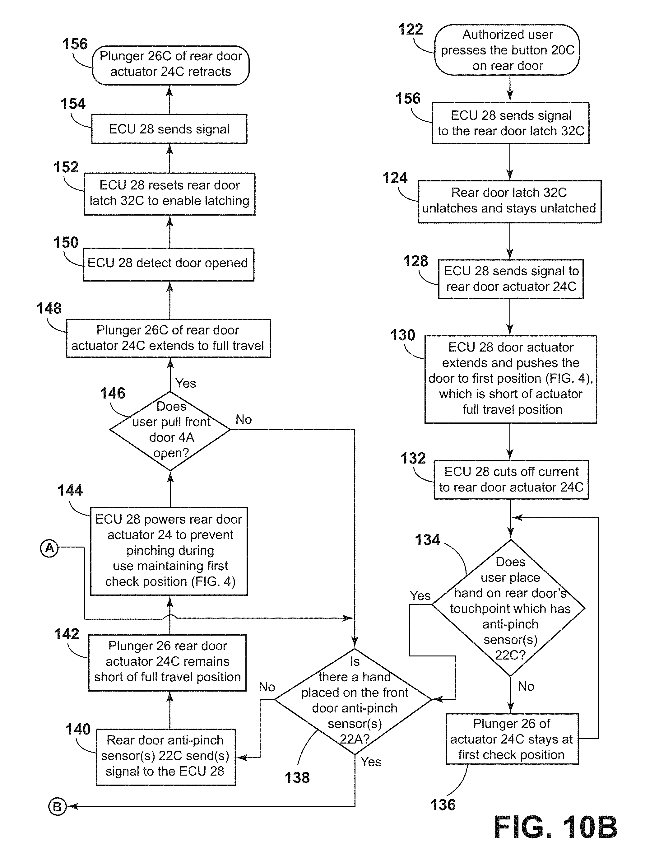
[0037] The flow chart of FIGS. 10A and 10B shows operation of a vehicle 1 including adjacent front and rear doors (e.g. FIGS. 2 and 3). Front door operation begins at step 88 (FIG. 10A), and rear door operation begins at step 122 (FIG. 10B). Steps 88-110 of FIG. 10A are substantially similar to steps 54-72 described above in FIG. 9, and steps 122-136 of FIG. 10B are substantially similar to steps 54-66 of FIG. 9. However, if the rear door is opened, and if a hand is detected by the front door anti pinch sensors 22A (step 138; FIG. 10B), the process moves from step 138 to step 158 (FIG. 10A), and the anti-pinch sensor 22A of the front door sends a signal to the ECU 28. At step 160, the ECU 28 then powers both the front and rear door actuators 24A and 24C to maintain the doors in the first check position (FIG. 4) to prevent pinching. At step 162, a user pulls the rear door 6A open, the process continues to step 138 (FIG. 10B). If a user does not pull the rear door open at step 162, the process continues as shown at step 164. At step 112 (optional) the ECU 28 determines that the front door 4A is open because plunger 26A is at full travel (FIG. 5). Similarly, at step 148 (FIG. 10B), if the rear door actuator is at full travel the ECU 28 determines at step 150 that the rear doors opened. It will be understood that the vehicle doors may include sensors that enable ECU 28 to determine if the door is fully opened, such that the ECU 28 does not necessarily need to use full travel of plungers 26 to determine if the door is fully open. After the ECU 28 detects that the front or rear door is fully open, the ECU 28 resets the powered latches and retracts the plungers of the powered door actuators 24A and 24C to permit a user to return the door to a closed position.
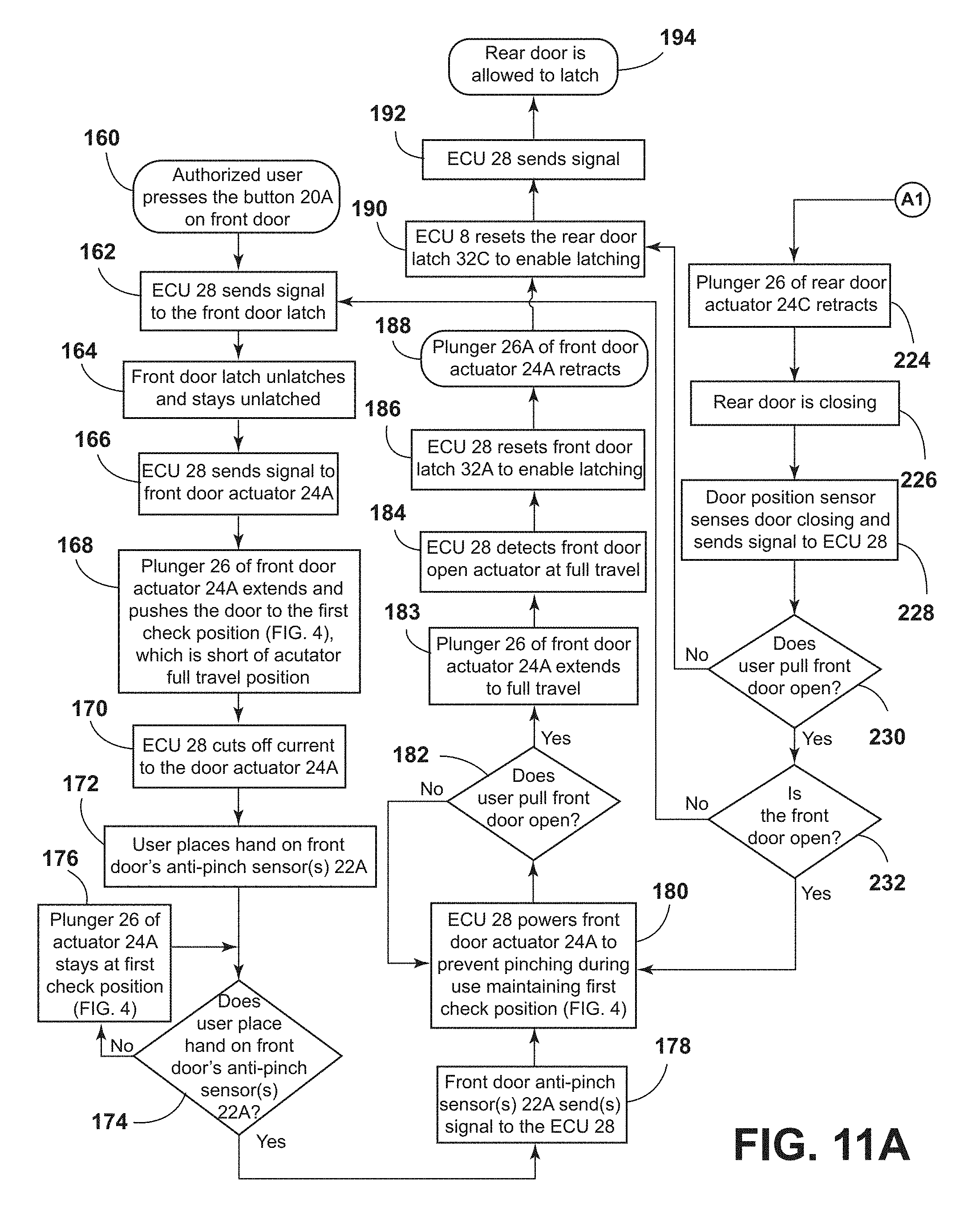
[0038] The flow chart of FIGS. 11A and 11B shows operation of a vehicle 1 including front and rear doors and door position sensors. Operation of the front door generally begins at step 160 (FIG. 11A), and operation of the rear door generally begins at step 196 (FIG. 11B). The door operations of FIGS. 11A and 11B are similar to the operations of FIGS. 10A and 10B, respectively. However, rear door operation further includes determining if the front door is open at step 232 (FIG. 11A). If the front door is not open, the process continues to step 162 as shown in FIG. 11A. Thus, as shown in FIG. 11A if the rear door is closed and the front door is open (Step 232), the ECU 28 unlatches the front door is shown at steps 162 and 164. [Omer why is this??]
[0039] The flow chart of FIGS. 12A and 12B shows operation of a vehicle including front and rear doors with powered latches 32A and 32C that comprise cinching latches. The operation shown in FIGS. 12A and 12B is generally similar to the vehicle door operations described above. However, in FIGS. 12A and 12B the ECU 28 actuates the cinching sensors as required.
[0040] The flow chart of FIGS. 13A and 13B shows operation of a vehicle including front and rear doors having powered cinching latches, door position sensors, and anti-pinch sensors. The operations shown in FIGS. 13A and 13B are generally similar to the operations discussed above in connection with FIGS. 9, 10A, 10B, 11A and 11B, and 12A and 12B. However, as shown in FIGS. 13A and 13B, if the vehicle includes both cinching latches and door position sensors, the ECU 28 utilizes the door position data to control the cinching latches and/or the powered door opening mechanism.
[0041] It is to be understood that variations and modifications can be made on the aforementioned structure without departing from the concepts of the present invention, and further it is to be understood that such concepts are intended to be covered by the following claims unless these claims by their language expressly state otherwise.
* * * * *
D00000
D00001
D00002
D00003
D00004
D00005
D00006
D00007
D00008
D00009
D00010
D00011
D00012

XML
uspto.report is an independent third-party trademark research tool that is not affiliated, endorsed, or sponsored by the United States Patent and Trademark Office (USPTO) or any other governmental organization. The information provided by uspto.report is based on publicly available data at the time of writing and is intended for informational purposes only.
While we strive to provide accurate and up-to-date information, we do not guarantee the accuracy, completeness, reliability, or suitability of the information displayed on this site. The use of this site is at your own risk. Any reliance you place on such information is therefore strictly at your own risk.
All official trademark data, including owner information, should be verified by visiting the official USPTO website at www.uspto.gov. This site is not intended to replace professional legal advice and should not be used as a substitute for consulting with a legal professional who is knowledgeable about trademark law.