A Demolition Robot Control Device And System
Mehra; Rajinder ; et al.
U.S. patent application number 16/345383 was filed with the patent office on 2019-08-15 for a demolition robot control device and system. The applicant listed for this patent is HUSQVARNA AB. Invention is credited to Rajinder Mehra, Tommy Olsson.
| Application Number | 20190249394 16/345383 |
| Document ID | / |
| Family ID | 62025371 |
| Filed Date | 2019-08-15 |


| United States Patent Application | 20190249394 |
| Kind Code | A1 |
| Mehra; Rajinder ; et al. | August 15, 2019 |
A DEMOLITION ROBOT CONTROL DEVICE AND SYSTEM
Abstract
A demolition robot control device is provided including processing circuitry configured to receive control data indicative of a selected transportation mode of a plurality of transportation modes and cause an adjustment of a demolition robot configuration based on the control data. The plurality of transportation modes includes a work mode, a transport mode, and an inclined surface mode. A demolition robot control system is also disclosed.
| Inventors: | Mehra; Rajinder; (Johanneshov, SE) ; Olsson; Tommy; (Molndal, SE) | ||||||||||
| Applicant: |
|
||||||||||
|---|---|---|---|---|---|---|---|---|---|---|---|
| Family ID: | 62025371 | ||||||||||
| Appl. No.: | 16/345383 | ||||||||||
| Filed: | October 25, 2017 | ||||||||||
| PCT Filed: | October 25, 2017 | ||||||||||
| PCT NO: | PCT/SE2017/051048 | ||||||||||
| 371 Date: | April 26, 2019 |
| Current U.S. Class: | 1/1 |
| Current CPC Class: | E02F 9/261 20130101; E02F 9/205 20130101; E02F 3/965 20130101; E04G 23/08 20130101 |
| International Class: | E02F 9/20 20060101 E02F009/20; E02F 3/96 20060101 E02F003/96; E02F 9/26 20060101 E02F009/26; E04G 23/08 20060101 E04G023/08 |
Foreign Application Data
| Date | Code | Application Number |
|---|---|---|
| Oct 28, 2016 | SE | 1651425-9 |
Claims
1. A demolition robot control device comprising processing circuitry configured to: receive control data indicative of a selected transportation mode of a plurality of transportation modes, wherein the plurality of transportation modes includes a work mode, a transport mode, and an inclined surface mode; and cause an adjustment of a demolition robot configuration based on the control data.
2. The demolition robot control device of claim 1, wherein the selected transportation mode is the inclined surface mode and the control data includes a direction of inclination of an inclined surface, and wherein adjusting the demolition robot configuration is further based on the direction of inclination.
3. The demolition robot control device of claim 1, wherein the selected transportation mode is the inclined surface mode, and wherein adjusting the demolition robot configuration comprises positioning of a counter weight.
4. The demolition robot control device of claim 1, wherein the selected transportation mode is the inclined surface mode, and wherein the processing circuitry is further configured to: receive sensor data or a site map associated with the inclined surface; and determine an inclination angle of the inclined surface, wherein adjusting the demolition robot configuration is further based on the inclination angle.
5. The demolition robot control device of claim 4, wherein the processing circuitry is further configured to: compare the inclination angle to a predetermined incline threshold.
6. The demolition robot control device of claim 1, wherein the selected transportation mode is the inclined surface mode, and wherein the processing circuitry is further configured to: compare a projected path to dimensions associated with the inclined surface.
7. The demolition robot control device of claim 6, wherein the processing circuitry is further configured to: cause a further adjustment of the demolition robot configuration based on the comparison of the projected path and the dimensions associated with the inclined surface.
8. The demolition robot control device of claim 1, wherein the selected transportation mode is the inclined surface mode, and wherein the processing circuitry is further configured to: receive an indication of an attachment of a pull cable.
9. The demolition robot control device of claim 1, wherein the selected transportation mode is the inclined surface mode, and wherein the processing circuitry is further configured to: receive an indication of an operator location; and compare the operation location to a safety threshold.
10. The demolition robot control device of claim 1, wherein the selected transportation mode is the inclined surface mode, and wherein the processing circuitry is further configured to enable propagation of the inclined surface based on satisfying one or more safety interlocks.
11. A demolition robot control system comprising: a demolition robot; and a demolition robot control device comprising processing circuitry configured to: receive control data indicative of a selected transportation mode of a plurality of transportation modes, wherein the plurality of transportation modes includes a work mode, a transport mode, and an inclined surface mode; and cause an adjustment of a demolition robot configuration based on the control data.
12. The demolition robot control system of claim 11, wherein the selected transportation mode is the inclined surface mode and the control data includes a direction of inclination of an inclined surface, and wherein adjusting the demolition robot configuration is further based on the direction of inclination.
13. The demolition robot control system of claim 11, wherein the selected transportation mode is the inclined surface mode, and wherein adjusting the demolition robot configuration comprises positioning of a counter weight.
14. The demolition robot control system of claim 11, wherein the selected transportation mode is the inclined surface mode, and wherein the processing circuitry is further configured to: receive sensor data or a site map associated with the inclined surface; and determine an inclination angle of the inclined surface, wherein adjusting the demolition robot configuration is further based on the inclination angle.
15. The demolition robot control system of claim 14, wherein the processing circuitry is further configured to: compare the inclination angle to a predetermined incline threshold.
16. The demolition robot control system of claim 11, wherein the selected transportation mode is the inclined surface mode, and wherein the processing circuitry is further configured to: compare a projected path to dimensions associated with the inclined surface.
17. The demolition robot control system of claim 16, wherein the processing circuitry is further configured to: cause a further adjustment of the demolition robot configuration based on the comparison of the projected path and the dimensions associated with the inclined surface.
18. The demolition robot control system of claim 11, wherein the selected transportation mode is the inclined surface mode, and wherein the processing circuitry is further configured to: receive an indication of an attachment of a pull cable.
19. The demolition robot control system of claim 11, wherein the selected transportation mode is the inclined surface mode, and wherein the processing circuitry is further configured to: receive an indication of an operator location; and compare the operation location to a safety threshold.
20. The demolition robot control system of claim 11, wherein the selected transportation mode is the inclined surface mode, and wherein the processing circuitry if further configured to enable propagation of the inclined surface based on satisfying one or more safety interlocks.
Description
TECHNICAL FIELD
[0001] Example embodiments generally relate to robotic devices and, more particularly, relate to adjusting a demolition robot configuration based on a transportation mode.
BACKGROUND
[0002] Typically, demolition robots are manually controlled by an operator to perform work and/or move from one location to the next. The operator may adjust the configuration of the demolition robot based on the current task, such as by lowering outriggers for stability and controlling a control arm to perform work. Additionally, the operator may retract the outriggers and control arm, and move the demolition device using tracks in a transport mode.
BRIEF SUMMARY OF SOME EXAMPLES
[0003] In an example embodiment, a demolition robot control device is provided including processing circuitry configured to receive control data indicative of a selected transportation mode of a plurality of transportation modes and cause an adjustment of a demolition robot configuration based on the control data. The plurality of transportation modes include a work mode, a transport mode, and an inclined surface mode.
[0004] In another example embodiment, a demolition robot control system is provided including a demolition robot and a demolition robot control device. The demolition robot control device may include processing circuitry configured to receive control data indicative of a selected transportation mode of a plurality of transportation modes and cause an adjustment of a demolition robot configuration based on the control data. The plurality of transportation modes may include a work mode, a transport mode, and an inclined surface mode.
BRIEF DESCRIPTION OF THE SEVERAL VIEWS OF THE DRAWING(S)
[0005] Having thus described the invention in general terms, reference will now be made to the accompanying drawings, which are not necessarily drawn to scale, and wherein:
[0006] FIG. 1 illustrates of a block diagram of a system according to an example embodiment;
[0007] FIG. 2 illustrates a block diagram of one example of onboard electronics or processing circuitry that may be used in connection with employment of an example embodiment;
[0008] FIG. 3 illustrates a demolition robot according to an example embodiment; and
[0009] FIG. 4 illustrates an example site map according to an example embodiment.
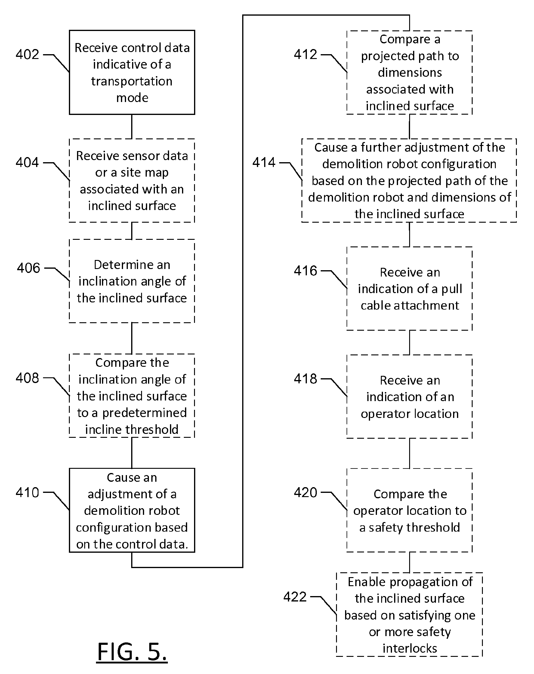
[0010] FIG. 5 illustrates a block diagram of a method according to an example embodiment.
DETAILED DESCRIPTION
[0011] Some example embodiments now will be described more fully hereinafter with reference to the accompanying drawings, in which some, but not all example embodiments are shown. Indeed, the examples described and pictured herein should not be construed as being limiting as to the scope, applicability or configuration of the present disclosure. Rather, these example embodiments are provided so that this disclosure will satisfy applicable legal requirements Like reference numerals refer to like elements throughout. Furthermore, as used herein, the term "or" is to be interpreted as a logical operator that results in true whenever one or more of its operands are true. As used herein, operable coupling should be understood to relate to direct or indirect connection that, in either case, enables functional interconnection of components that are operably coupled to each other.
[0012] In an example embodiment, a demolition robot control device may be provide configured to cause an adjustment of a demolition robot configuration based on an indication of a selected transportation mode. The selected transportation mode may be one of a plurality of possible transportation modes including a work mode, transport mode, or inclined surface mode (or stair mode). In some example embodiments, the adjustment of the demolition device configuration may include positioning outriggers, control arms, or the like for the current mode.
[0013] In an example embodiment, in which the selected transportation mode is the inclined surface mode, the demolition robot control device may determine the direction of incline and/or the inclination angle and the adjustment of the demolition robot configuration may be further based on the direction of the incline of inclination angle. In some example embodiments, the adjustment of the demolition robot configuration in the inclined surface mode may include positioning outriggers, the control arm, a counter weight, or the like, to compensate for the change in angle and weight distribution of the demolition device as it traverses the inclined surface.
[0014] In an example embodiment the demolition robot control device may compare a projected path to dimensions associated with the inclined surface, such as walls, ceilings, turns, or the like. The demolition robot control device may cause further adjustments to the demolition robot configuration to limit or prevent impact with the walls, ceiling, or the like.
[0015] In some example embodiments, the demolition robot may include a pull cable or winch to provide further stability when traversing the inclined surface. The demolition robot control device may be configured to receive an indication of attachment of the pull cable. In another example embodiment, the demolition robot control device may be configured to receive an indication of the operator location. The demolition robot control device may provide warnings or prevent propagation of the demolition robot in an instance in which one or more safety interlocks are not satisfied. For example, propagation the demolition robot may be enabled in an instance in which the operator location satisfies a safety threshold, the inclination angle satisfies a predetermined threshold, an indication of pull cable attachment has been received, the demolition robot has completed the configuration adjustment, and/or the demolition robot configuration will not impact walls in the projected path.
[0016] FIG. 1 illustrates an example system in which an embodiment of the present invention may be employed. In this regard, FIG. 1 illustrates a generic example of a system in which various devices that are examples of construction equipment may utilize a network for the performance of construction site coordination according to an example embodiment. As shown in FIG. 1, a system 10 according to an example embodiment may include one or more client devices (e.g. demolition robots 20 and remote control devices 50). Notably, although FIG. 1 illustrates four devices 20, 50 it should be appreciated that many more devices 20, 50 may be included in some embodiments and thus, the four devices 20, 50 of FIG. 1 are simply used to illustrate a multiplicity of devices 20, 50 and the number of devices 20, 50 is in no way limiting to other example embodiments. In this regard, example embodiments are scalable to inclusion of any number of devices 20, 50 being tied into the system 10. Moreover, it should be appreciated that FIG. 1 illustrates one example embodiment in which shared resources may be allocated within a community of networked devices (e.g. devices 20, 50). However, it should be appreciated that the architecture of various example embodiments may vary. Thus, the example of FIG. 1 is merely provided for ease of explanation of one example embodiment and should not be considered to be limiting with respect to the architecture of the system 10. Accordingly, for example, some embodiments may have specific sets of devices 20, 50 that are associated with corresponding specific servers that belong to or are utilized by a particular organization, entity or group over a single network (e.g. network 30). However, in other embodiments, multiple different sets of devices 20, 50 may be enabled to access other servers associated with different organizations, entities or groups via the same or a different network.
[0017] The devices 20, 50 may, in some cases, each include sensory, computing and/or communication devices associated with different devices 20, 50 that belong to or are associated with a single organization, for example fleet management of devices 20, 50 at a construction site. In another example, a first device 20, 50 may be associated with a first facility or location of a first organization. Meanwhile, a second device may be associated with a second facility or location of the first organization. As such, for example, some of the devices 20, 50 may be associated with the first organization, while other ones of the devices 20, 50 are associated with a second organization. Thus, for example, the devices 20, 50 may be remotely located from each other, collocated, or combinations thereof. However, in some embodiments, each of the devices 20, 50 may be associated with individuals, locations or entities associated with different organizations or merely representing individual devices.
[0018] Each one of the demolition robots 20 may include a housing inside which a power unit or motor (not shown) is housed. In some embodiments, the power unit may be an electric motor, an internal combustion engine, hydraulic system, pneumatic system, combustion chamber, or the like. The demolition robots 20 may each further include a working element, which may be operably coupled to a control arm. The working element may be operated via the power unit to perform demolition operations, such as drilling, cutting, demolishing, or the like. The construction devices 20 may include sensors for monitoring location, device operation, orientation, or the like, as discussed below in reference to FIG. 2.
[0019] Each of the remote control devices 50 may include sensors, such as location sensors, cameras, scanners, or the like and/or a user interface, as discussed below in reference to FIG. 2. The remote control device 50 may, in some cases, be useful for controlling operation of the demolition robot 20. In some instances, the remote control device 50 may communicate directly with the demolition robot 20 via wireline or wireless communication.
[0020] In an example embodiment, each of the devices 20, 50 may include onboard circuitry 22 which may include or otherwise be embodied as a computing device (e.g. a processor, microcontroller, processing circuitry, or the like) capable of communication with a network 30 and/or each other . As such, for example, each one of the devices 20, 50 may include (or otherwise have access to) memory for storing instructions or applications for the performance of various functions and a corresponding processor for executing stored instructions or applications and a corresponding processor or processing circuitry. Each one of the devices 20, 50 may also include software and/or corresponding hardware (e.g. the onboard circuitry 22) for enabling the performance of the respective functions of the clients as described below. In an example embodiment, one or more of the devices 20, 50 may be configured to execute applications or functions implemented via software for enabling a respective one of the devices 20, 50 to communicate with each other or the network 30 for requesting and/or receiving information and/or services via the network 30 and/or for providing data to other devices via the network 30. The information or services receivable at the devices 20, 50 may include deliverable components (e.g. downloadable software to configure the onboard circuitry 22 of the devices 20, 50, or information for consumption or utilization at the onboard circuitry 22 of the devices 20, 50).
[0021] The network 30 may be a data network, such as a local area network (LAN), a metropolitan area network (MAN), a wide area network (WAN) (e.g. the Internet), and/or the like, which may couple the devices 20, 50 to devices such as processing elements (e.g. personal computers, server computers or the like) and/or databases. Communication between the network 30, the devices 20, 50 and the devices or databases (e.g. servers) to which the devices 20, 50 are coupled may be accomplished by either wired or wireless communication mechanisms and corresponding communication protocols. However, in some embodiments, the devices 20, 50 may operate independently of any network connectivity.
[0022] In an example embodiment, other devices to which the devices 20, 50 may be coupled via the network 30 may include a server network 32 including one or more application servers (e.g. application server 40), and/or a database server 42, which together may form respective elements of the server network 32. Although the application server 40 and the database server 42 are each referred to as "servers," this does not necessarily imply that they are embodied on separate servers or devices. As such, for example, a single server or device may include both entities and the database server 42 could merely be represented by a database or group of databases physically located on the same server or device as the application server 40. The application server 40 may include monitoring circuitry 44 (which may be similar to or different from the onboard circuitry 22 of the devices 20, 50) that may include hardware and/or software for configuring the application server 40 to perform various functions. As such, for example, the application server 40 may include processing logic and memory enabling the application server 40 to access and/or execute stored computer readable instructions for performing various functions.
[0023] In an example embodiment, one function that may be provided by the application server 40 (e.g. via the monitoring circuitry 44) may be the provision of services relating to causing adjustment of a demolition robot configuration based on a selected transportation mode, as will be described in greater detail below. For example, the application server 40 may be local or remote and configured to receive data from the devices 20, 50 and process the data to coordinate construction site operations, as described herein. Thus, for example, the onboard circuitry 22 may be configured to send the data to the application server 40 for the application server to coordinate adjustments to the demolition robot configuration and/or movement operations, or have actions associated therewith (e.g. send information, alerts, or safety interlocks to devices 20, 50). In some embodiments, the application server 40 may be configured to provide devices 20, 50 with instructions (e.g. for execution by the onboard circuitry 22) for taking prescribed actions when corresponding control data is received or safety interlocks are met. However, in other cases the onboard circuitry 22 may control the devices 20, 50 without any assistance or connection to application server 44 or network 30.
[0024] The system 10 of FIG. 1 may cause adjustments to a demolition robot configuration on the basis of the execution of functionality that is executed using either or both of the onboard circuitry 22 and the monitoring circuitry 44. FIG. 2 illustrates a block diagram showing components that may be associated with embodiment of the onboard circuitry 22 and/or the monitoring circuitry 44 according to an example embodiment. As shown in FIG. 2, the onboard circuitry 22 and/or the monitoring circuitry 44 may include or otherwise be embodied as a demolition robot control (DRC) device 100. The DRC device 100 may be embodied in a demolition robot 20, a remote control device 50, the monitoring circuitry, a separate computing device, or be distributed among the devices 20, 50, and/or a separate computing device. The DRC device 100 may include processing circuitry 110 of an example embodiment, as described herein. In this regard, for example, the DRC device 100 may utilize the processing circuitry 110 to provide electronic control inputs to one or more functional units of the onboard circuitry 22 and/or the monitoring circuitry 44 and to process data generated by the one or more functional units regarding various indications of device activity (e.g. operational parameters and/or location information) relating to a corresponding one of the devices 20, 50. In some cases, the processing circuitry 110 may be configured to perform data processing, control function execution and/or other processing and management services according to an example embodiment. In some embodiments, the processing circuitry 110 may be embodied as a chip or chip set. In other words, the processing circuitry 110 may comprise one or more physical packages (e.g. chips) including materials, components and/or wires on a structural assembly (e.g. a baseboard). The structural assembly may provide physical strength, conservation of size, and/or limitation of electrical interaction for component circuitry included thereon. The processing circuitry 110 may therefore, in some cases, be configured to implement an embodiment of the present invention on a single chip or as a single "system on a chip." As such, in some cases, a chip or chipset may constitute means for performing one or more operations for providing the functionalities described herein.
[0025] In an example embodiment, the processing circuitry 110 may include one or more instances of a processor 112 and memory 114 that may be in communication with or otherwise control a device interface 120 and, in some cases, a user interface 130. As such, the processing circuitry 110 may be embodied as a circuit chip (e.g. an integrated circuit chip) configured (e.g. with hardware, software or a combination of hardware and software) to perform operations described herein. However, in some embodiments, the processing circuitry 110 may be embodied as a portion of an on-board computer on a device being monitored (e.g. one of the devices 20, 50), while in other embodiments, the processing circuitry 110 may be embodied as a remote computer that monitors device activity for one or more devices.
[0026] The user interface 130 may be in communication with the processing circuitry 110 to receive an indication of a user input at the user interface 130 and/or to provide an audible, visual, tactile or other output to the user. As such, the user interface 130 may include, for example, a display, one or more levers, switches, buttons or keys (e.g. function buttons), and/or other input/output mechanisms. In an example embodiment, the user interface 130 may include one or a plurality of lights, a display, a speaker, a tone generator, a vibration unit and/or the like.
[0027] The device interface 120 may include one or more interface mechanisms for enabling communication with other devices (e.g. sensors of the sensor network 140, or functional units of the DRC device 100 or other equipment on which an example embodiment may be employed). In some cases, the device interface 120 may be any means such as a device or circuitry embodied in either hardware, or a combination of hardware and software that is configured to receive and/or transmit data from/to sensors in communication with the processing circuitry 110 via internal communication systems of the DRC device 100. In some cases, the device interface 120 may further include wireless communication equipment (e.g. a one way or two way radio, Bluetooth, near field communication, or the like) for at least communicating information from the DRC device 100 to a network and, in the case of a two way radio, in some cases receiving information from a network or other device (e.g. the other one of the demolition robot 20 or the remote control device 50, and or other demolition robots 20 and/or remote control devices 50.
[0028] The processor 112 may be embodied in a number of different ways. For example, the processor 112 may be embodied as various processing means such as one or more of a microprocessor or other processing element, a coprocessor, a controller or various other computing or processing devices including integrated circuits such as, for example, an ASIC (application specific integrated circuit), an FPGA (field programmable gate array), or the like. In an example embodiment, the processor 112 may be configured to execute instructions stored in the memory 114 or otherwise accessible to the processor 112. As such, whether configured by hardware or by a combination of hardware and software, the processor 112 may represent an entity (e.g. physically embodied in circuitry--in the form of processing circuitry 110) capable of performing operations according to embodiments of the present invention while configured accordingly. Thus, for example, when the processor 112 is embodied as an ASIC, FPGA or the like, the processor 112 may be specifically configured hardware for conducting the operations described herein. Alternatively, as another example, when the processor 112 is embodied as an executor of software instructions, the instructions may specifically configure the processor 112 to perform the operations described herein.
[0029] In an example embodiment, the processor 112 (or the processing circuitry 110) may be embodied as, include or otherwise control the operation of the DRC device 100 based on inputs received by the processing circuitry 110. As such, in some embodiments, the processor 112 (or the processing circuitry 110) may be said to cause each of the operations described in connection with the DRC device 100 in relation to operation the DRC device 100 relative to undertaking the corresponding functionalities associated therewith responsive to execution of instructions or algorithms configuring the processor 112 (or processing circuitry 110) accordingly.
[0030] In an example embodiment, the memory 114 may include one or more non-transitory memory devices such as, for example, volatile and/or non-volatile memory that may be either fixed or removable. The memory 114 may be configured to store information, data, applications, instructions or the like for enabling the processing circuitry 110 to carry out various functions in accordance with example embodiments of the present invention. For example, the memory 114 could be configured to buffer input data for processing by the processor 112. Additionally or alternatively, the memory 114 could be configured to store instructions for execution by the processor 112. As yet another alternative or additional capability, the memory 114 may include one or more databases that may store a variety of data sets responsive to input from the sensor network 140, the DRC device 100, or any other functional units that may be associated with the DRC device 100. Among the contents of the memory 114, applications may be stored for execution by the processor 112 in order to carry out the functionality associated with each respective application.
[0031] In some embodiments, the processing circuitry 110 may communicate with electronic components and/or sensors of the sensor network 140 (e.g. sensors that measure variable values related to device location, orientation, and/or environmental conditions like direction of inclination, inclination angles, enclosure dimensions, and/or the like, and/or sensors that measure device movement by employing movement sensor circuitry) of the demolition robot 20 via the device interface 120. In one embodiment, sensors of the sensor network 140 of one or more ones of the devices 20, 50 may communicate with the processing circuitry 110 of a remote monitoring computer via the network 30 and the device interface 120 using wireless communication or by downloading data that is transferred using a removable memory device that is first in communication with the demolition robot 20 to load data indicative of device activity, and is then (e.g. via the device interface 120) in communication with the remote monitoring computer (e.g. associated with the monitoring circuitry 44).
[0032] In some embodiments, the processing circuitry 110 may communicate with movement sensor circuitry of the devices 20, 50 (e.g. when the processing circuitry 110 is implemented as the onboard circuitry 22), or may receive information indicative of device location from movement sensor circuitry of one or more devices being monitored (e.g. when the processing circuitry is implemented as the monitoring circuitry 44). The movement sensor circuitry may include movement sensors (e.g. portions of the sensor network 140) such as one or more accelerometers and/or gyroscopes, or may include global positioning system (GPS) or other location determining equipment.
[0033] The movement sensor circuitry (if employed) may be configured to provide indications of movement of the devices 20, 50 based on data provided by the one or more accelerometers and/or gyroscopes, and/or based on GPS or local position determining capabilities. In other words, the movement sensor circuitry may be configured to detect movement of the devices 20, 50 based on inertia-related measurements or other location determining information. In some example embodiments, the movement sensor circuitry may include orientation sensors, configured to detect the orientation of a device or component thereof, particularly the working element of the device, relative to the determined location or a reference point/structure of the determined location.
[0034] FIG. 3 illustrates a demolition robot 20 according to an example embodiment of the present invention. As shown in FIG. 3, the demolition robot 20 may include a plurality of outriggers (e.g., support legs) 25 which may extend and retract to secure and/or stabilized the demolition robot 20 prior to and/or during operation of the demolition robot 20. The outriggers 25 are illustrated as being in a fully retracted position in FIG. 1. The demolition robot 20 may further comprise caterpillar tracks 26 configured to move the demolition robot 20 across a variety of landscapes (e.g., flat surfaces; debris covered surfaces; inclined surfaces; such as ramps and stairs; or the like) and a rotating tower 27. The demolition robot 20 may also include a control arm 21, which may be moved to engage a variety of working elements and/or perform a variety of work-tasks. The demolition robot 20 may receive control data from the DRC device 100, which may be embodied in the demolition robot 20 or at the remote control device 50. The remote control device 50 may include a user interface, such as user interface 130, including a first control stick 23 and a second control stick 24. The remote control device 50 may also include a variety of switches and/or buttons which may be used in conjunction with the control sticks 23, 24 to control operation of each of the functionally operational features of the demolition robot 20.
[0035] As stated above, the demolition robot 20 may receive control data from the DRC device 100. The control data may be indicative of a selected transportation mode of the demolition robot 20. In an example embodiment, the selected transportation mode that may be one of a plurality of transportation modes may include without limitation, a work mode, a transport mode, and an inclined surface mode. The DRC device 100 may cause the demolition robot 20 to adjust a demolition robot configuration based on control data indicative of the selected transportation mode. The work mode may be used to maximize stability of the demolition robot 20 during operation of the control arm 21 for demolition operations. The work mode may include a demolition robot configuration defining the outriggers 25 in an extended position to secure the demolition robot 20 in place. The transport mode may used to move the demolition robot 20 over a substantially level surface, for example, inclinations of less than 20 degrees, 30 degrees, or the like. The transport mode may include a demolition robot configuration defining retraction of the outriggers 25, such as vertically or horizontally, toward the center of the demolition robot 20. In an example embodiment, the transport mode demolition robot configuration may define a control arm position as raised at least a predetermined distance from a floor, such as 6 inches, 12 inches, 18 inches or the like. The inclined surface mode (or stair mode) may be used to transport the demolition device over an inclined surface, such as a ramp, hill, stairs, or the like, for example surfaces with an average inclination angle of greater than 20 degrees, 30 degrees, or the like. The inclined surface mode may include a demolition robot configuration defining further retracting of the outriggers 25 to the demolition robot 20, such as to a maximum retraction position, centering the rotating tower 27 over the caterpillar tracks 26, retracting the control arm 21 to a storage position, e.g. fully retracted, or other adjustments which may lower or center the center of gravity of the demolition robot 20 to enable more stable transport.
[0036] In an example embodiment, the DRC device 100 may receive data indicative of a direction of incline, e.g. upward or downward. The data indicative of the direction of the incline may be received from the remote control device 50, such as an operator selection using the user interface 130. Additionally or alternatively, the data indicative of the direction of incline may be sensor data from one or more sensors of a sensor network 140, indicative of one or more surfaces in the vicinity of the demolition robot. In another embodiment, the DRC device 100 may receive a site map and/or the location data associated with the demolition robot 20. The site map may be indicative of surfaces of a construction site and the DRC device 100 may use the location data to determine the inclination associated with the surfaces proximate to the demolition robot 20 based on the site map, an example site map is depicted in FIG. 4.
[0037] The DRC device 100 may include a direction of inclination as a portion of the control data. In an example embodiment in which the control data includes the direction of inclination the adjustment of the demolition robot configuration may include positioning a counter weight 29. The positioning of the counter weight 29 may shift the center of gravity of the demolition robot 20 to be more stable when traversing the inclined surface. For example, in an instance in which the direction of inclination is upward, the demolition robot configuration may define or direct positioning of the counter weight 29 at a forward position, e.g. the portion of the demolition robot 20 which may lead the traversal of the inclined surface, to maintain positive engagement of the caterpillar tracks 26 on the inclined surface and prevent a backward roll. Similarly, in an instance in which the direction of inclination is downward, the demolition robot configuration may define or direct the counter weight 29 at a rearward position, to maintain positive engagement of the caterpillar track 26 on the inclined surface and prevent a forward roll.
[0038] In some example embodiments, the sensor data and/or site map may include further data associated with the inclined surface, such as the angle of inclination or type of inclination (e.g. stairs, ramp, or the like. The DRC device 100 may determine an angle of inclination of the inclined surface based on the sensor data, location data, user input, and/or site map. The DRC device 100 may cause additional adjustments to the demolition robot configuration based on the inclination angle. In an example embodiment, the DRC device 100 may determine a counter balance position of for the counter weight 29 based on the inclination angle. Adjusting the demolition robot configuration may include positioning the counter weight 29 at the counter balance position. Additionally or alternatively, the DRC device 100 may determine a control arm balance position, based on the inclination angle. Adjusting the demolition robot configuration may include positioning the control arm 21 and or rotating tower 27 to the control arm balance position, to provide a further adjustment to the center of gravity of the demolition robot 20.
[0039] In an example embodiment, the DRC device 100 may determine a propagation path for the demolition robot 20. The propagation path may be based on user input, such as from the user interface 130 defining a starting location and an ending location in the site map. In another example embodiment, the propagation path may be the area within a predetermined distance of a driving direction of the demolition robot 20.
[0040] The DRC device 100 may determine dimensions associated with the inclined surface, such as distances, turns, walls ceilings, or the like. The dimensions may be determined based on sensor data, for example, a captured image from a camera, proximity sensors, three dimensional scanning, or the like. Additionally, or alternatively, the site map may include measurements of one or more features, and the DRC device 100 may determine the dimensions associated with the inclined surface based on the site map and location data.
[0041] In some example embodiments, the DRC device 100 may compare the propagation path, which may include the physical dimensions of the demolition robot 20 to the dimensions associated with the inclined surface. The DRC device 100 may determine one or more contact points (e.g. points at which a portion of the demolition robot 20 would impact a wall ceiling or the like in the current demolition robot configuration) associated with traversal of the propagation path based on the comparison of the propagation path to the dimensions associated with the inclined surface. The DRC device 100 may determine further adjustments to the demolition device configuration to prevent or limit contact points. In some cases, the DRC device may additionally determine one or more locations to cause execution of the additional adjustments to the demolition robot configuration, such as at turning points of stairs. Additionally or alternatively, the DRC device 100 may determine that the demolition robot 20 is not able to traverse the propagation path without making contact with walls ceiling or the like. An indication may be provided to the operator or device operation may be halted in such cases.
[0042] In an example embodiment, the demolition robot 20 may include a pull cable 32, an anchor, such as a hook 30, and a winch. The hook 30 may be attached to an anchor point such as a pad eye and the winch may provide tension on the pull cable 32. The tension on the pull cable may provide resistance to gravity, preventing sliding of the demolition robot 20 on the inclined surface, and/preventing forward or backward rolling of the demolition robot 20.
[0043] In some example embodiments, the DRC device 100 may enable movement or propagation over the inclined surface in an instance in which one or more safety interlocks are satisfied, and disable the demolition robot 20 in an instance in which one or more safety interlocks are not satisfied. The demolition robot 20 may be disabled by mechanically, electrically, or programmatically preventing operation or propagation of the demolition robot 20.
[0044] In some example embodiments, the DRC device 100 may compare the inclination angle to a predetermined incline threshold. The predetermined incline threshold may be based on an angle at which the demolition robot 20 may safely traverse the inclined surface without sliding or rolling, for example 50 degrees, 60 degrees, or the like. In an instance in which the inclination angle satisfies, e.g. is less than, the predetermined incline threshold, the safety interlock may be satisfied enabling propagation of the demolition robot 20 over the inclined surface.
[0045] In some example embodiments, the DRC device 100 may receive an indication of attachment of the pull cable 32. The indication of attachment of the pull cable 32 may be received from a sensor, such as a portion of the sensor network 140, or from the user interface 130. In an example embodiment, receiving the indication of attachment of the pull cable 32 in the inclined surface mode may satisfy the safety interlock, and the DRC device 100 may enable propagation of the demolition robot 20 over the inclined surface.
[0046] In some embodiments, the DRC device 100 may include multiple predetermined incline thresholds. A first incline threshold, such as 30 degrees, 40 degrees or the like, may be satisfied (e.g. an inclination angle less than the incline threshold) without an indication of attachment of the pull cable 32. A second incline threshold (above the first incline threshold), such as 45 degrees, 50 degrees, 60 degrees, or the like may be satisfied in an instance in which the indication of attachment of the pull cable 32 is received. The DRC device 100 may determine whether the safety interlock is satisfied and enable propagation of the demolition robot 20 over the inclined surface, in an instance in which the first or second incline threshold is satisfied.
[0047] In an example embodiment, the safety interlock may include a determination of a passable propagation path or projected path, e.g. a propagation path in which the demolition robot 20 will not contact a wall, ceiling, or the like, while traversing the inclined surface. In an instance in which the DRC device 100 determines that the demolition robot 20 will not contact walls, ceilings, or the like, (based on the comparison of the dimensions associated with the inclined surface and the propagation path), the DRC device 100 may determine the safety interlock is satisfied and enable propagation of the demolition robot 20 over the inclined surface. The passable propagation path may or may not include additional demolition robot 20 configuration adjustments.
[0048] In some example embodiments, the DRC device 100 may receive an indication of an operator location. The indication of the operator location may be sensor data or location data received from one or more sensors of the sensor network 140, or a user input received from the user interface 130. The indication of the operator location may be associated with the operator, other workers, supervisors, or the like. The DRC device 100 may compare the operator location to a safety threshold. The safety threshold may be a radius around the demolition robot 20, the propagation path, a predetermined area in the direction of the demolition robot propagation, the area below the demolition robot 20 on the inclined surface, or the like. The safety threshold may prevent operators from being in a position in which injury may occur due to operation, sliding, rolling, adjustments to the demolition robot configuration, or the like. The DRC device 100 may determine the safety interlock is satisfied, in an instance in which the operator location satisfies, e.g. is not within, the safety threshold. Although discussed separately, the DRC device 100 may utilize any, some or all of the safety interlocks in any combination.
[0049] FIG. 4 illustrates a site map 310 according to an example embodiment. The site map 310 may include or the demolition robot 20 may determine the location of the demolition robot 20 and inclined surfaces 312, such as ramps or stairs, or other site features. The inclined surface 312 depicted is a stair case to a higher floor. The site map 310 may also include or the demolition robot 20 may determine dimensions 314 associated with the inclined site feature 312, e.g. inclined surface. For example, the site map 312 may include the dimensions including the ceiling height, the width of the stair case, width of landing, and/or narrowest points of a landing, or other dimensional measurements. In some embodiments, the site map 310 may include or the demolition robot 20 may determine the direction of inclination of the inclined surface 318, e.g. up in the case, the inclination angle, and/or a projected path 316. Additionally or alternatively, the site map 310 may include or the demolition robot may determine the operator location 320.
[0050] In some cases, a method of utilizing the DRC device 100 and/or one or more demolition robots 20 according to an example embodiment may be provided. FIG. 5 illustrates a block diagram of some activities that may be associated with one example of such a method. In some embodiments, the processing circuitry 110 (which may include a processor capable of executing instructions stored in a non-transitory computer readable medium/memory) may be configured to implement a control algorithm for the DRC device 100 and/or the one or more demolition robots 20 according to the method.
[0051] In an example embodiment, the method may include receiving control data indicative of a transportation mode at operation 402 and causing an adjustment to a demolition robot configuration based on the control data at operation 404.
[0052] In some embodiments, the method may include additional, optional operations, and/or the operations described above may be modified or augmented. Some examples of modifications, optional operations, and augmentations are described below, as indicated by dashed lines. In an example embodiment, the method may include receiving sensor data or a site map associated with an inclined surface at operation 404 determining an inclination angle of the inclined surface at operation 406, and comparing the inclination angle of the inclined surface to a predetermined incline threshold at operation 408. In some example embodiments, the method may include comparing a projected path to dimensions associated with the inclined surface at operation 412, causing a further adjustment of the demolition robot configuration based on the projected path of the demolition robot and the dimensions of the inclined surface at operation 414, and receiving an indication of a pull cable attachment at operation 416. The method may also include, in some example embodiments, receiving an indication of an operator location at operation 418, comparing the operator location to a safety threshold at operation 420, and enabling propagation of the inclined surface based on satisfying one or more safety interlocks at operation 422.
[0053] In an example embodiment, the DRC device 100 may comprise a processor (e.g. the processor 112) or processing circuitry 110 configured to perform some or each of the operations (402-422) described above. The processor 112 may, for example, be configured to perform the operations (402-422) by performing hardware implemented logical functions, executing stored instructions, or executing algorithms for performing each of the operations. In some embodiments, the processor 112 or processing circuitry 110 may be further configured for additional operations or optional modifications to operations 402-422. In this regard, for example, the selected transportation mode is the inclined surface mode and the control data includes a direction of inclination of an inclined surface and adjusting the demolition robot configuration is further based on the direction of inclination. In an example embodiment, the selected transportation mode is the inclined surface mode and adjusting the demolition robot configuration comprises positioning of a counter weight. In an example embodiment, the selected transportation mode is the inclined surface mode and the processing circuitry is further configured to receive sensor data or a site map associated with the inclined surface and determine an inclination angle of the inclined surface. The adjusting the demolition robot configuration is further based on the inclination angle. In some example embodiments, the processing circuitry is further configured to compare the inclination angle to a predetermined incline threshold. In an example embodiment, the selected transportation mode is the inclined surface mode and the processing circuitry is further configured to compare a projected path to dimensions associated with the inclined surface. In some example embodiments, the processing circuitry is further configured to cause a further adjustment of the demolition robot configuration based on the comparison of the projected path and the dimensions associated with the inclined surface. In an example embodiment, the selected transportation mode is the inclined surface mode and the processing circuitry is further configured to receive an indication of an attachment of a pull cable. In some example embodiments, the selected transportation mode is the inclined surface mode and the processing circuitry is further configured to receive an indication of an operator location and compare the operation location to a safety threshold. In some example embodiments, the selected transportation mode is the inclined surface mode and the processing circuitry if further configured to enable propagation of the inclined surface based on satisfying one or more safety interlocks.
[0054] Many modifications and other embodiments of the inventions set forth herein will come to mind to one skilled in the art to which these inventions pertain having the benefit of the teachings presented in the foregoing descriptions and the associated drawings. Therefore, it is to be understood that the inventions are not to be limited to the specific embodiments disclosed and that modifications and other embodiments are intended to be included within the scope of the appended claims. Moreover, although the foregoing descriptions and the associated drawings describe exemplary embodiments in the context of certain exemplary combinations of elements and/or functions, it should be appreciated that different combinations of elements and/or functions may be provided by alternative embodiments without departing from the scope of the appended claims. In this regard, for example, different combinations of elements and/or functions than those explicitly described above are also contemplated as may be set forth in some of the appended claims. In cases where advantages, benefits or solutions to problems are described herein, it should be appreciated that such advantages, benefits and/or solutions may be applicable to some example embodiments, but not necessarily all example embodiments. Thus, any advantages, benefits or solutions described herein should not be thought of as being critical, required or essential to all embodiments or to that which is claimed herein. Although specific terms are employed herein, they are used in a generic and descriptive sense only and not for purposes of limitation.
* * * * *
D00000
D00001
D00002
D00003
D00004
D00005
XML
uspto.report is an independent third-party trademark research tool that is not affiliated, endorsed, or sponsored by the United States Patent and Trademark Office (USPTO) or any other governmental organization. The information provided by uspto.report is based on publicly available data at the time of writing and is intended for informational purposes only.
While we strive to provide accurate and up-to-date information, we do not guarantee the accuracy, completeness, reliability, or suitability of the information displayed on this site. The use of this site is at your own risk. Any reliance you place on such information is therefore strictly at your own risk.
All official trademark data, including owner information, should be verified by visiting the official USPTO website at www.uspto.gov. This site is not intended to replace professional legal advice and should not be used as a substitute for consulting with a legal professional who is knowledgeable about trademark law.