Integrated Membrane Solar Fuel Production Assembly
LEE; Joun ; et al.
U.S. patent application number 16/336873 was filed with the patent office on 2019-08-15 for integrated membrane solar fuel production assembly. The applicant listed for this patent is HYPERSOLAR, INC., UNIVERSITY OF IOWA RESEARCH FOUNDATION. Invention is credited to Wei CHENG, Syed Mubeen Jawahar HUSSAINI, Joun LEE, Timothy YOUNG.
| Application Number | 20190249313 16/336873 |
| Document ID | / |
| Family ID | 60022219 |
| Filed Date | 2019-08-15 |


| United States Patent Application | 20190249313 |
| Kind Code | A1 |
| LEE; Joun ; et al. | August 15, 2019 |
INTEGRATED MEMBRANE SOLAR FUEL PRODUCTION ASSEMBLY
Abstract
A solar fuel production assembly comprises a separation structure including an ion conducting membrane structurally integrated with one or more solar fuel production units that absorb solar energy to drive one or more redox reactions. A reduction half-reaction occurs on a first side of the separation structure to produce one or more reduction products and an associated oxidation half-reaction occurs on an opposite second side of the separation structure to produce one or more oxidation products. The one or more reduction products are collectable from the first side and the one or more oxidation products are collectable from the second side of the separation structure. The ion conducting membrane provides facile transport of ions to reduce ion transfer ohmic losses associated with the one or more redox reactions, and also provides for separation of the one or more reduction products from the one or more oxidation products.
| Inventors: | LEE; Joun; (Iowa City, IA) ; HUSSAINI; Syed Mubeen Jawahar; (Iowa City, IA) ; CHENG; Wei; (Iowa City, IA) ; YOUNG; Timothy; (Iowa City, IA) | ||||||||||
| Applicant: |
|
||||||||||
|---|---|---|---|---|---|---|---|---|---|---|---|
| Family ID: | 60022219 | ||||||||||
| Appl. No.: | 16/336873 | ||||||||||
| Filed: | September 26, 2017 | ||||||||||
| PCT Filed: | September 26, 2017 | ||||||||||
| PCT NO: | PCT/US2017/053408 | ||||||||||
| 371 Date: | March 26, 2019 |
Related U.S. Patent Documents
| Application Number | Filing Date | Patent Number | ||
|---|---|---|---|---|
| 62399747 | Sep 26, 2016 | |||
| Current U.S. Class: | 1/1 |
| Current CPC Class: | Y02P 20/133 20151101; C25B 1/003 20130101; C25B 1/10 20130101; Y02E 70/10 20130101; Y02E 60/366 20130101; C25B 9/10 20130101; Y02P 20/134 20151101 |
| International Class: | C25B 1/00 20060101 C25B001/00; C25B 1/10 20060101 C25B001/10; C25B 9/10 20060101 C25B009/10 |
Claims
1. A solar fuel production assembly, comprising: a separation structure including one or more ion-conducting membranes structurally integrated with one or more solar fuel production units; wherein the one or more solar fuel production units absorb solar energy to drive one or more redox reactions, with a reduction half-reaction occurring on a first side of the separation structure to produce one or more reduction products associated with the reduction half-reaction and an associated oxidation half-reaction occurring on a second side of the separation structure opposite from the first side to produce one or more oxidation products associated with the associated oxidation half-reaction, wherein the one or more reduction products are collectable from the first side and the one or more oxidation products are collectable from the second side, and wherein the one or more ion-conducting membranes provides facile transport of ions to reduce ion transfer ohmic losses associated with the one or more redox reactions, and also provides for separation of the one or more reduction products from the one or more oxidation products.
2. An assembly according to claim 1, wherein the separation structure comprises a perforated solar fuel production unit having holes, wherein each hole is covered or filled by one of the one or more ion-conducting membranes.
3. An assembly according to claim 2, wherein the solar fuel production unit is perforated using at least one of: a chemical etching process, a vapor etching process, or a mechanical perforation process.
4. An assembly according to claim 1, wherein the separation structure comprises a perforated ion-conducting membrane having one or more separated solar fuel production units embedded into respective perforations of the perforated ion-conducting membrane.
5. An assembly according to claim 1, wherein the one or more solar fuel production units includes a multi-junction photosynthetically active heterostructure comprising: a continuous sheet-like material forming or supporting a protective structure having a plurality of cavities defining electrically insulating partitions; a plurality of independent light absorbing units, each including one or more types or regions of n-type or p-type semiconductor material, with each independent light absorbing unit being disposed entirely within one of the plurality of cavities of the protective structure such that the protective structure partially covers and protects the semiconductor material of each independent light absorbing unit from corrosion and such that each independent light absorbing unit is separated from and independent of other light absorbing units of the multi-junction photosynthetically active heterostructure; one or more cathodes coupled to the independent light absorbing units; and one or more anodes coupled to the independent light absorbing units and being isolated from the one or more cathodes so that each independent light absorbing unit is autonomous from other light absorbing units.
6. An assembly according to claim 1, wherein the one or more solar fuel production units comprise a thin film monolithic or multi-junction tandem solar cell coated with protective coating to prevent chemical and electrochemical corrosion and capped with oxidation and reduction electrocatalyst.
7. An assembly according to claim 1, wherein each of the one or more ion-conducting membranes is an anion exchange membrane or a cation exchange membrane.
8. A method for generation of fuel using solar power, the method comprising: providing or receiving a solar fuel production assembly comprising; a separation structure including one or more ion-conducting membranes structurally integrated with one or more solar fuel production units; wherein the one or more solar fuel production units absorb solar energy to drive one or more redox reactions, with a reduction half-reaction occurring on a first side of the separation structure to produce one or more reduction products associated with the reduction half-reaction and an associated oxidation half-reaction occurring on a second side of the separation structure opposite from the first side to produce one or more oxidation products associated with the associated oxidation half-reaction, wherein the one or more reduction products are collectable from the first side and the one or more oxidation products are collectable from the second side, and wherein the one or more ion-conducting membranes provides facile transport of ions to reduce ion transfer ohmic losses associated with the one or more redox reactions, and also provides for separation of the one or more reduction products from the one or more oxidation products; providing an electrolyte to the first side and the second side of the separation structure; submitting the solar fuel production assembly to solar radiation to enable the solar radiation to drive the one or more redox reactions to generate the one or more reduction reaction products and the one or more oxidation reaction products; and collecting at least one of the one or more reduction reaction products and the one or more oxidation reaction products.
9. A method according to claim 8, wherein the electrolyte comprises water.
10. A method according to claim 8, wherein the electrolyte comprises at least one of: wastewater, seawater, and brine water.
11. A method according to claim 8, wherein the one or more redox reactions comprise water electrolysis, wherein the one or more reduction products comprise hydrogen gas, and the one or more oxidation products comprise oxygen gas.
12. A method according to claim 8, wherein the separation structure comprises a perforated solar fuel production unit having holes, wherein each hole is covered or filled by one of the one or more ion-conducting membranes.
13. A method according to claim 12, wherein the solar fuel production unit is perforated using at least one of: a chemical etching process, a vapor etching process, or a mechanical perforation process.
14. A method according to claim 8, wherein the separation structure comprises a perforated ion-conducting membrane having one or more separated solar fuel production units embedded into respective perforations of the perforated ion-conducting membrane.
15. A method according to claim 8, wherein the one or more solar fuel production units includes a multi-junction photosynthetically active heterostructure comprising: a continuous sheet-like material forming or supporting a protective structure having a plurality of cavities defining electrically insulating partitions; a plurality of independent light absorbing units, each including one or more types or regions of n-type or p-type semiconductor material, with each independent light absorbing unit being disposed entirely within one of the plurality of cavities of the protective structure such that the protective structure partially covers and protects the semiconductor material of each independent light absorbing unit from corrosion and such that each independent light absorbing unit is separated from and independent of other light absorbing units of the multi-junction photosynthetically active heterostructure; one or more cathodes coupled to the independent light absorbing units; one or more anodes coupled to the independent light absorbing units and being isolated from the one or more cathodes so that each independent light absorbing unit is autonomous from other light absorbing units; wherein each anode and cathode is capped with an oxidation and reduction electrocatalyst; and a hydrogen permeable layer covering the one or more cathodes.
16. A method according to claim 8, wherein the one or more solar fuel production units comprise a thin film monolithic or multi-junction tandem solar cell coated with protective coating to prevent chemical and electrochemical corrosion and capped with oxidation and reduction electrocatalyst.
17. (canceled)
18. An assembly according to claim 4, wherein at least one of the separated solar fuel production units is perforated and has at least one hole, the at least one hole being covered or filled by an ion-conducting membrane.
19. An assembly according to claim 5, wherein each anode and cathode is capped with an oxidation and reduction electrocatalyst.
20. An assembly according to claim 5, further comprising a hydrogen permeable layer covering the one or more cathodes.
21. A method according to claim 14, wherein at least one of the separated solar fuel production units is perforated and has at least one hole, the at least one hole being covered or filled by an ion-conducting membrane.
Description
CROSS-REFERENCE TO RELATED APPLICATION
[0001] This application claims the benefit of priority to U.S. Provisional Application Ser. No. 62/399,747, filed on Sep. 26, 2016, entitled "INTEGRATED MEMBRANE SOLAR FUEL PRODUCTION ASSEMBLY," which application is incorporated by reference herein in its entirety.
BACKGROUND
[0002] There is great interest in renewable energy generation in order to replace conventional fossil fuels. This includes utilizing solar, wind, and biomass for producing fuels. Solar energy is particularly interesting because it is a fundamental renewable energy source that theoretically can be used to continuously, noiselessly, and passively generate fuels once the infrastructure to produce fuel from solar energy has been developed.
[0003] Conventionally, photovoltaic devices have been used to convert solar energy to another form of energy to electrical energy. Photovoltaic devices include one or more semiconductor materials that are capable of capturing photons from solar irradiation and converting at least a portion of their energy into electrical energy. For solar fuel production, the electrical energy generated from the solar energy is used to drive chemical reactions on a catalyst surface, where the catalyst of interest is either placed in a separate electrolyzer device or integrated with the photovoltaic assembly.
SUMMARY
[0004] In an example, the present disclosure describes a solar fuel production assembly comprising a separation structure including an ion-conducting membrane structurally integrated with one or more solar fuel production units. The one or more solar fuel production units absorb solar energy to drive one or more redox reactions, such as one or more reduction half-reactions occurring on a first side of the separation structure to produce one or more reduction products associated with the reduction half-reaction and one or more associated oxidation half-reactions occurring on a second side of the separation structure opposite from the first side to produce one or more oxidation products associated with the associated oxidation half-reaction. The one or more reduction products are collectable from the first side of the separation structure and the one or more oxidation products are collectable from the second side of the separation structure. The ion-conducting membrane provides facile transport of ions to reduce ion transfer ohmic losses associated with the one or more redox reactions, and also provides for separation of the one or more reduction products from the one or more oxidation products.
[0005] In some examples, the one or more solar fuel production units of the solar production assembly each include a multi-junction photosynthetically active heterostructure that includes a continuous sheet-like material forming or supporting a protective structure having a plurality of cavities defining electrically insulating partitions, a plurality of independent light absorbing units, each including one or more types or regions of n-type or p-type semiconductor material, with each independent light absorbing unit being disposed entirely within one of the plurality of cavities of the protective structure such that the protective structure partially covers and protects the semiconductor material of each independent light absorbing unit from corrosion and such that each independent light absorbing unit is separated from and independent of other light absorbing units of the multi-junction photosynthetically active heterostructure, one or more cathodes electrically coupled to the independent light absorbing units, one or more anodes electrically coupled to the independent light absorbing units and electrically isolated from the one or more cathodes so that each independent light absorbing unit is autonomous from other light absorbing units, and a hydrogen permeable layer covering the one or more cathodes, wherein each anode and cathode is capped with an oxidation and reduction electrocatalyst
BRIEF DESCRIPTION OF THE FIGURES
[0006] In order to describe the manner in which the advantages and features of the assemblies and methods described herein can be obtained. A more particular description of the subject matter briefly described above will be rendered by reference to specific embodiments thereof, which are illustrated in the appended drawings. Understanding that these drawings depict only exemplary embodiments and are not therefore to be considered as limiting of the scope of the inventions described herein, the subject matter will be described and explained with additional specificity and detail through the use of the accompanying drawings in which:
[0007] FIG. 1 is an exploded perspective view of an example solar fuel production assembly including a subassembly comprising one or more ion-exchange membranes integrated with one or more solar fuel production units that convert energy from light to electrical energy sufficient to electrolytically convert water molecules to hydrogen gas and oxygen gas, in accordance with various embodiments of the present disclosure.
[0008] FIG. 2 is a cross-sectional side view of the example solar fuel production assembly of FIG. 1, in accordance with various embodiments of the present disclosure.
[0009] FIG. 3 is a front view of another example of a solar fuel production assembly including an integrated ion-exchange membrane and fuel production unit subassembly, similar to the example fuel production assembly shown in FIGS. 1 and 2, in accordance with various embodiments of the present disclosure.
[0010] FIG. 4 is a cross-sectional view of the example solar fuel production assembly of FIG. 3, taken along section 4-4 in FIG. 3, in accordance with various embodiments of the present disclosure.
[0011] FIG. 5 is a photograph of an example integrated ion-exchange membrane and fuel production unit subassembly that can be used in either of the example solar fuel production assemblies of FIGS. 1-4. FIG. 5 shows the integrated subassembly during operation, with gas bubbles being generated at an interface between the solar fuel production unit and an electrolyte, in accordance with various embodiments of the present disclosure.
[0012] FIG. 6 is a front view of another example of an integrated ion-exchange membrane and solar fuel production unit subassembly that can be used in either of the solar fuel production assemblies of FIGS. 1-4, in accordance with various embodiments of the present disclosure.
[0013] FIG. 7 is another example of an integrated subassembly ion-exchange membrane and solar fuel production unit subassembly that can be used in either of the solar fuel production assemblies of FIGS. 1-4, in accordance with various embodiments of the present disclosure.
[0014] FIG. 8 is another example of an integrated subassembly ion-exchange membrane and solar fuel production unit subassembly that can be used in either of the solar fuel production assemblies of FIGS. 1-4, in accordance with various embodiments of the present disclosure.
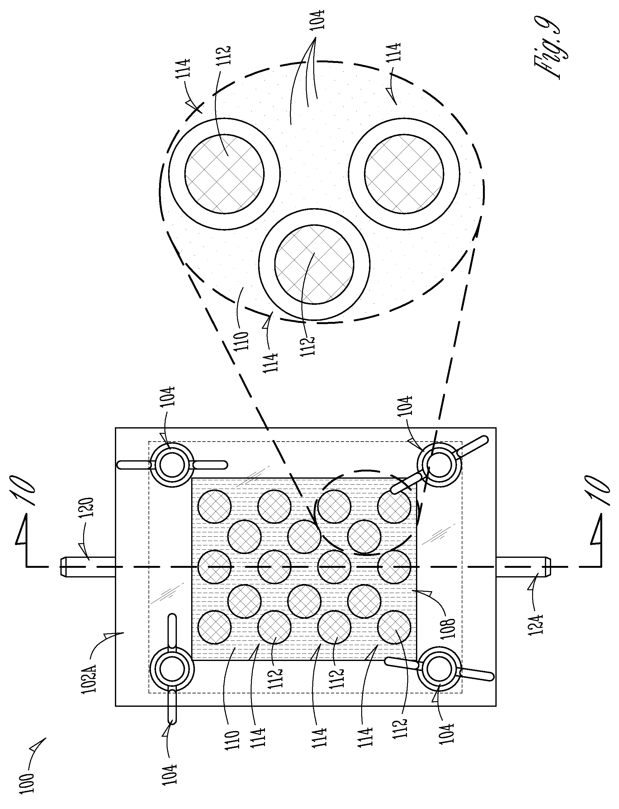
[0015] FIG. 9 is a front view of another example another example of a solar fuel production assembly that includes another example of an integrated ion-exchange membrane and fuel production unit subassembly, in accordance with various embodiments of the present disclosure.
[0016] FIG. 10 is a cross-sectional side view of the example solar fuel production assembly shown in FIG. 9, taken along section 10-10 in FIG. 9, in accordance with various embodiments of the present disclosure.
[0017] FIG. 11 is a bar graph of the solar-to-hydrogen conversion efficiency of a solid solar cell and a perforated solar cell, as compared in EXAMPLE 1.
[0018] FIG. 12 is a Bode impedance log-log plot of electrochemical impedance spectroscopy measured on the solid solar cell of EXAMPLE 1.
DETAILED DESCRIPTION
[0019] Using solar energy to drive the electrolysis of water has become an increased area of research. Electrolysis of water involves the use of electrical energy to split water molecules into hydrogen gas (H.sub.2) and oxygen gas (O.sub.2), according to overall hydrolysis reaction [1].
2 H.sub.2O.sub.(l).fwdarw.2 H.sub.2(g)+O.sub.2(g) [1]
[0020] As will be appreciated by those of skill in the art, the electrolysis of reaction [1] is made up of two half reactions--an oxidation half reaction and a reduction half reaction. The oxidation half reaction occurs at the anode and produces one or more oxidation products, such as oxygen gas (O.sub.2) and hydrogen ions (H.sup.+). The reduction half reaction occurs at the cathode and produces one or more reduction products, such as hydrogen gas (H.sub.2) and hydroxide ions (OH.sup.-). The H.sub.2 gas can be used as a clean fuel source, while the O.sub.2 gas co-product can be collected for further industrial use or simply discarded as a clean byproduct of the reaction. The overall water hydrolysis reaction [1] has a standard potential of -1.23 V, meaning that at standard temperature and pressure, reaction [1] theoretically requires an applied potential difference of 1.23 V to drive the endothermic decomposition for every two water molecules (as in the overall hydrolysis reaction [1]). However, in practical application, water electrolysis requires an additional potential difference, commonly referred to as "overpotential," to overcome various limitations, such as activation barriers and system inefficiencies.
[0021] One common example of such a limitation in solar-powered electrolysis is ohmic losses related to the hindrance of ion diffusion that drives reaction [1] between an anode region and a cathode region of the solar fuel cell. For instance, to maintain reaction [1] in the forward direction toward the H.sub.2 and O.sub.2 co-products and minimize required overpotentials, oxidation products (i.e., H.sup.+ ions) formed at the anode are transported through an electrolyte to the cathode (e.g., where H.sup.+ ions can be reduced to form the H.sub.2 gas co-product) and/or reduction products (i.e., OH.sup.- ions) formed at the cathode are transported through the electrolyte to the anode (e.g., where the OH.sup.- ions can be oxidized to form the O.sub.2 gas co-product or water). In some instances, limits on ion transport cause a counteracting ion concentration overpotential that limits the effectiveness of the solar fuel cell and of the process that uses the fuel cell to generate H.sub.2 fuel.
[0022] Another common limitation on solar-powered electrolysis is inefficiency caused by undesirable recombination of oxidation and reduction products, i.e., reaction of H.sup.+ ions and OH.sup.- ions back into water molecules, reducing the overall efficiency of the process as well as the yield of the solar-derived fuel sought to be produced. In addition, in some examples, the solar-powered fuel cell can produce products or co-products that can produce an undesirable effect. For example, in water splitting applications, the H.sub.2 and O.sub.2 co-products can form a flammable or even explosive mixture that can pose a safety hazard.
[0023] The subject matter present disclosure is not limited to embodiments that solve any disadvantages or that operate only in environments described herein. Rather, the preceding information has been provided to illustrate an exemplary technology area where some of the embodiments and methods described herein can be practiced.
[0024] Certain embodiments described herein are directed to effective and efficient solar fuel production units for use in a solar-powered fuel production process. In particular, some embodiments described herein can be particularly effective when used in the electrolysis of water for the efficient generation of H.sub.2 fuel. One or more of the embodiments described herein are configured to separate reduction products and oxidation products in order to beneficially enhance fuel production efficiency. One or more of the embodiments described herein are configured to provide for efficient ion transport and for reduced ohmic losses associated with ion transport compared to other known systems and methods for H.sub.2 fuel generation via solar-powered electrolysis of water.
[0025] In some embodiments, a solar fuel production assembly includes a reduction compartment separated from an oxidation compartment by a planar ion exchange membrane. The ion exchange membrane includes a plurality of embedded solar fuel production units distributed across the ion exchange medium so as to provide a surface area having a mixture of ion exchange functionality and solar radiation capture functionality.
[0026] FIGS. 1 and 2 show conceptual schematic views an exemplary embodiment of a solar fuel production assembly 10 (also referred to hereinafter as "the fuel production assembly 10" or simply as "the assembly 10"). FIG. 1 is an exploded perspective view of the assembly 10, while FIG. 2 is a cross-sectional side view of the fuel production assembly 10. As shown, an ion-exchange membrane 12 (also referred to simply as "the membrane 12") is embedded with a plurality of solar fuel production units 14 (also referred to as "fuel production units 14") to form an integrated membrane and fuel production unit subassembly 16, which will be referred to hereinafter as the "integrated subassembly 16" for brevity.
[0027] The integrated subassembly 16 is positionable within a housing to form the fuel production assembly 10. In the embodiment shown in FIGS. 1 and 2, the housing comprises two or more housing sections 18A, 18B (collectively referred to as "the housing sections 18" or simply as "the housing 18") that are coupled together onto or around the integrated subassembly 16. The housing 18, when assembled (i.e., when the housing sections 18A, 18B are coupled together), forms a housing chamber 20 in which at least a portion of the integrated subassembly 16 is positioned. In particular, the fuel production units 14 of the integrated subassembly 16 are positioned within the housing chamber 20. As mentioned above and described in more detail below, an electrolyte is also placed into the housing chamber 20 to provide a medium in which ions (i.e., H.sup.+ and OH.sup.- ions) can be formed and through which the ions can be transported.
[0028] The housing 18 also includes at least one solar face 24A, 24B (collectively referred to as "the solar faces 24" or "the solar face 24") that is able to transmit, or at least partially transmit, light (such as solar energy) that is irradiated onto the solar fuel production assembly 10 into the main housing chamber 20. Light transmitted through the one or more solar faces 24A, 24B can then irradiate onto the fuel production units 14 so that at least a portion of the photons in the light can be captured by the fuel production units 14 for conversion to fuel (i.e., H.sub.2 fuel), as described in more detail below. In the embodiment shown in FIGS. 1 and 2, the housing 18 includes a first solar face 24A that is part of a first housing section 18A and a second solar face 24B that is part of a second housing section 24B. In the embodiment shown, each solar face 24A, 24B forms a major portion of the surface area of that particular housing section 18A, 18B so that a large proportion of the light that is irradiated onto the solar fuel production assembly 10 can pass into the housing chamber 20 where, at least theoretically, it can be captured and converted by the fuel production units 14. Each of the one or more solar faces 24 can be made from any material that is able to transmit a substantial portion of light that is emitted onto the solar face 24 including, but not limited to, glass or polymers that are transparent, substantially transparent, or semi-transparent to light, and in particular to solar energy.
[0029] In some embodiments, the ion-exchange membrane 12 acts to divide the housing chamber 20 into two sub-chambers 26 and 28 (best seen in FIG. 2), which are also referred to herein as compartments 26 and 28. As described in more detail below, in some embodiments, the fuel production units 14 of the integrated subassembly 16 can be configured so that a first side of each fuel production unit 14 is positioned to be exposed to the first compartment 26 and will produce one or more reduction products 30 (i.e., H.sub.2 gas and OH.sup.- ions formed via a water electrolysis reduction half reaction). In these embodiments, the fuel production units 14 can be further configured so that a second side of each fuel production unit 14 is positioned to be exposed to the second compartment 28 and will produce one or more oxidation products 32 (i.e., O.sub.2 gas and H.sup.+ ions via a water electrolysis oxidation half reaction). In other words, in such embodiments, the first side and second side of each fuel production unit 14 are configured to be the cathode and the anode, respectively. For this reason, in some embodiments the first compartment 26 will be referred to as "the reduction compartment 26" (i.e., because it is where the reduction half reaction occurs and the one or more reduction products 30 are produced) and the second compartment 28 will be referred to as "the oxidation compartment 28" (i.e., because it is where the oxidation half reaction occurs and the one or more oxidation products 32 are produced). However, those of skill in the art will appreciate that the configuration of the fuel production units 14 can be reversed from that which is shown in FIG. 2, i.e., such that the first compartment 26 is where the one or more oxidation products 32 are produced and the second compartment 28 is where the one or more reduction products 30 are produced, without varying from the scope of the present disclosure. In some examples, the ion-exchange membrane 12 is configured to allow for the transport of ions produced by one or both of the reduction half reaction (such as OH.sup.- ions) and the oxidation half reaction (such as H.sup.- ions). In some examples, the ion exchange membrane 12 is configured in particular to allow H.sup.+ ions to be transported from the oxidation compartment 28 to the reduction compartment 28 such that the H.sup.+ ions may be reduced to produce H.sub.2 gas as a product gas. In such cases, the membrane 12 may be referred to as an "H.sup.+ transport membrane" or a "proton transport membrane."
[0030] In the embodiment best seen in FIG. 1, the ion-exchange membrane 12 maintains spacing between adjacent fuel production units 14 such that there is sufficient membrane surface area for ion exchange between the reduction compartment 26 on one side of the ion-exchange membrane 12 and the oxidation compartment 28 on the opposite side of the membrane 12. In the embodiment shown in FIG. 1, the fuel production units 14 are integrated with the ion-exchange membrane 12 in a grid pattern, i.e., with a specified number of rows and a specified number of columns of the production units 14 (eight (8) rows and two (2) columns in the embodiment shown in FIG. 1, with only four (4) of the rows shown in the cross-sectional view of FIG. 2). The grid-like arrangement of the illustrated embodiment for the integrated subassembly 16 enables facile transport of ions across the membrane 12, which in turn can reduce or minimize the distance through which the ions must travel in order to complete the "circuit" of the electrolysis half reactions, and thereby reduce or minimize ohmic losses related to ion transport.
[0031] The embodiment illustrated in FIG. 2 also shows that the housing 18 and the ion-exchange membrane 12 separately maintains the one or more reduction products 30 and the one or more oxidation products 32 within their respective compartments 26 and 28, preventing easy mixing and recombination of the reaction products 30, 32. For example, in some embodiments, the reduction products 30 formed in the reduction compartment 26 include H.sub.2 gas, and the oxidation products 32 formed in the oxidation compartment 28 include O.sub.2 gas. The ion exchange membrane 12, while allowing transport of ions from one compartment to another (such as OH.sup.- ions from the reduction compartment 26 to the oxidation compartment 28 or H.sup.+ ions from the oxidation compartment 28 to the reduction compartment 26), prevents the passage of H.sub.2 gas from the reduction compartment 26 to the oxidation compartment 28 and of O.sub.2 gas from the oxidation compartment 28 to the reduction compartment 26.
[0032] In an embodiment, shown in FIGS. 1 and 2, each compartment 26, 28 includes a separate gas outlet, i.e., a first gas outlet 34 from the reduction compartment 26 and a separate second gas outlet 36 from the oxidation compartment 30, where each separate gas product may be extracted. In some embodiments, the first gas outlet 34 provides for the removal of H.sub.2 fuel gas 38 from the reduction compartment 26, such that the outlet 34 will also be referred to as the "reduction outlet 34" or the "H.sub.2 outlet 34." In some embodiments, the second gas outlet 36 provides for the removal of O.sub.2 co-product gas 40 from the oxidation compartment 28 such that the outlet 36 will also be referred to as the "oxidation outlet 36" "O.sub.2 outlet 36." Beneficially, the gaseous co-products are separated throughout operation of the fuel production assembly 10, preventing or minimizing co-product loss through recombination, which can also be potentially dangerous, as in the case of H.sub.2 and O.sub.2 recombination.
[0033] The integrated membrane solar fuel production assembly 10 illustrated in FIG. 1 beneficially enables separation of the one or more reduction products 30 and the one or more oxidation products 32 formed during operation as they are produced within the separate compartments 26, 28 of the assembly 10. In water splitting applications, where the primary reduction product 30 is H.sub.2 fuel gas 38 and the primary oxidation product 32 is O.sub.2 gas 40, the illustrated embodiment beneficially maintains separation of the generated H.sub.2 fuel gas 38 and the O.sub.2 co-product gas 38 on opposite sides of the membrane 12 in the reduction compartment 26 and in the oxidation compartment 28, respectively. Not only does this separation advantageously prevent recombination of the co-products and associated production losses, but the separation also keeps the product gases 38, 40 from mixing and forming a dangerous mixture with high explosion hazard. In contrast to other monolithic solar devices not configured for such a separation of co-products, the illustrated embodiment of the fuel production assembly 10 is both more effective and safer.
[0034] In addition, the illustrated embodiment of the fuel production assembly 10 is able to achieve this beneficial separation without introducing high ohmic losses. The configuration of the assembly 10, which combines an ion exchange membrane 12 with interspersed solar fuel production units 14, beneficially enables the separate compartments 26, 28 to be functionally separate with respect to the produced co-products 30, 32, yet close in physical proximity with relatively limited ion transport distances. This is in contrast to other solar devices that separate the co-products, which require longer distances for ion transport and therefore higher ohmic losses. In short, the illustrated embodiment of the fuel production assembly 10 is capable of achieving efficient and safe separation of products with minimum loss of efficiencies.
[0035] The fuel production assembly 10 also includes one or more liquid inlets 42, 44 for the introduction of water or electrolyte, or both, to the compartments 26, 28. In the embodiment shown in FIGS. 1 and 2, there is a separate and dedicated liquid inlet 42, 44 for each separate compartment 26, 28, i.e., a first liquid inlet 42 that feeds into the reduction compartment 26 and a separate second liquid inlet 44 that feeds into the oxidation compartment 28. In some embodiments, the liquid inlets 42, 44 are for feeding the electrolyte solution into the compartments 26, 28. Because the electrolyte solution that is fed into the reduction compartment 26 (shown as solution 46 in FIG. 2) contacts the cathode side of the fuel production units 14, electrolyte solution is typically referred to as "catholyte solution" or simply "catholyte" (as is typical with electrolyte that contacts the cathode in an electrolysis cell). Similarly, because the electrolyte solution that is added into the oxidation compartment 28 (shown as solution 38 in FIG. 2) contacts the anode side of the fuel production units 14, it is typically referred to as the "anolyte solution" or simply "anolyte" (as is typical with electrolyte that contacts the anode in an electrolysis cell).
[0036] In some embodiments, the catholyte added to the reduction compartment 26 is substantially the same or even identical to the anolyte added to the oxidation compartment 28. Alternatively, the catholyte and anolyte can be selected as different electrolyte solutions, depending on the specifications for each compartment 26, 28 within the fuel production assembly 10. Exemplary electrolyte sources that may be utilized as catholyte and/or anolyte include, but are not limited to: wastewater (e.g., organic, nitrate, phosphorous, and/or sulfur rich wastewater); seawater or other brines; fresh water; carbonated water; other water source (typically, a low quality or wastewater source), or combinations thereof.
[0037] In the example embodiment shown in FIGS. 1 and 2, a portion of the ion-exchange membrane 12, such as a periphery, is clamped between the housing sections 18A, 18B to secure the integrated subassembly 16 within the solar fuel production assembly 10. In some embodiments, however, one or more fasteners or fastening mechanisms can be used to secure the housing sections 18A, 18B together. FIGS. 3 and 4 show an alternative example embodiment of a fuel production assembly 50 where a set of fastening mechanism 52 are used to secure a first housing section 54A to a second housing section 54B. In the example embodiment shown in FIGS. 3 and 4, the fastening mechanisms 52 comprise sets of bolts and corresponding wing nuts shown, although other mechanical fasteners and fastening mechanism could be used. The housing sections 54A, 54B and their corresponding solar faces 56A, 56B of the fuel production assembly 50 shown in FIGS. 3 and 4 are similar to the housing sections 18A, 18B and the solar faces 24A, 24B of the fuel production assembly 10 of FIGS. 1 and 2, except that the housing sections 54A, 54B and the solar faces 56A, 56B are slightly modified to accommodate one or more structures of the fastening mechanisms 52 (e.g., holes or other openings through the solar faces 56A, 56B and the housing sections 54A, 54B to accommodate the bolts of the example fastening mechanisms 52). Similarly, the ion-exchange membrane 58 of the example fuel production assembly 50 of FIGS. 3 and 4 is similar to the ion-exchange membrane 12 of the fuel production assembly 10 of FIGS. 1 and 2, except that the ion-exchange membrane 58 has also been modified to accommodate
[0038] In some embodiments, the fastening mechanisms 52 can also act to couple the ion-exchange membrane of the assembly to its housing, rather than only relying on clamping the ion-exchange membrane 12 between the housing sections 18A, 18B. For example, the ion-exchange membrane 58 of the example fuel production assembly 50 of FIGS. 3 and 4 is similar to the ion-exchange membrane 12 of the fuel production assembly 10 of FIGS. 1 and 2, except that the ion-exchange membrane 58 has also been modified to accommodate the fastening mechanisms 52 (i.e., with openings in the ion-exchange membrane 58 that accommodate bolts of the fastening mechanisms 52).
[0039] Other than these modifications to accommodate the fastening mechanisms 52, the housing sections 54A, 54B, the solar faces 56A, 56B, and the ion-exchange membrane 58, can be substantially similar or identical to the housing sections 18A, 18B, the solar faces 24A, 24B, and the ion-exchange membrane 12, respectively, of the assembly 10 described herein with respect to FIGS. 1 and 2. Those of skill in the art will appreciate, therefore, that descriptions in other parts of the present disclosure of details regarding the housing sections 18A, 18B, the solar faces 24A, 24B, and the membrane 12 in other parts of this disclosure can apply to the housing sections 54A, 54B, the solar faces 56A, 56B, and the membrane 58 of the assembly 50 of FIGS. 3 and 4 even if those other parts of the present disclosure do not refer to reference numbers 54A, 54B, 56A, 56B, or 58. Other components of the example fuel production assembly 50 of FIGS. 3 and 4--such as the fuel production units 14, the first and second compartments 26 and 28 (also referred to herein as the reduction compartment 26 and the oxidation compartment 28), the first and second gas outlets 34 and 36 (also referred to herein as the H.sub.2 gas outlet 34 and the O.sub.2 gas outlet 36), and the one or more liquid inlets 42, 44--are substantially similar or even identical to those described above with respect to the assembly 10 of FIGS. 1 and 2, and as such the same reference numbers are used to indicate these components.
[0040] Although most of the examples described herein describe oxidation and reduction products in the context of electrolysis of water, it will be understood that other reduction and/or oxidation products may additionally or alternatively be generated using one or more of the described embodiments of the assembly 10 or assembly 50, or for any of the other assemblies described herein. In some examples, the one or more solar fuel production units 14 that are integrated with an ion-exchange membrane 12, 58 to form an integrated subassembly 16 may be utilized to generate, as reduction products, ammonia, formic acid, methanol, methane, oxalic acid, metals, sodium hydroxide, formaldehyde, carbon monoxide, ethylene glycol, nitrogen, and phosphorus. In some examples, the one or more integrated membrane solar fuel production units 14 may be utilized to generate, as oxidation products, chlorine, bromine, hydrogen peroxide, oxygen, fluorine, iodine, metal oxides, and sulfides. Those having skill in the art will understand that a variety of combinations of reduction products and oxidation products may be produced according to selected process inputs (e.g., the composition of the reactant or reactants fed to the assembly 10, 50 via the one or more feed inlets 42, 44) and operational configurations.
[0041] The plurality of solar fuel production units 14 may be formed as any suitable photosensitizer capable of capturing light energy and transferring electrons to the side of the unit facing the reduction/cathodic compartment 36 so that reduction half reactions can occur. In some embodiments, the solar fuel production units 14 also include one or more suitable electrocatalysts and/or protective layers. Examples of protective layer may include, for example, any suitable electrically insulating material, including, but not limited to A1203, SiO.sub.2, ZrO, AlF.sub.3, and TiF.sub.2, ZnO, TiO.sub.2, or combinations thereof.
[0042] In some examples, an electrocatalyst layer on the side of the fuel production units 14 that act as the cathode side (i.e., that are exposed to the reduction compartment 36) may include, for example, conductors including, but not limited to: noble metals, including platinum group metals such as platinum (Pt) or precious metals including gold (Au); transition metals; transition metal oxides (e.g. NiO); metal carbides (e.g., WC); metal sulfides (e.g. MoS.sub.2); electrically-conducting carbon containing materials, such as graphite, graphene, and carbon nanotubes; or combinations thereof. In some examples, an electrocatalyst layer on the side of the fuel production units 14 that act as the anode (i.e., that are exposed to the oxidation compartment 28) may include, for example, conductors including, but not limited to: metals; metal oxides; and mixtures of, metals including Ru, Ag, V, W, Fe, Ni, Pt, Pd, Ir, Cr, Mn, Cu, Ti, and metal sulfides (e.g., MoS.sub.2); electrical conducting carbon containing materials such as graphite, graphene, and carbon nanotubes; and combinations thereof
[0043] A semiconductor absorber portion of each of the solar fuel production units 14 can include one or more types of semiconductor materials (e.g., p-type and/or n-type) to form one or more p-n junctions or one or more Schottky junctions, as is known in the art of photovoltaic devices.
[0044] Examples of suitable p-type semiconductor materials include at least one of, but are not limited to, intrinsic or p-doped SnS, ZnS, CdS, CdSe, CdTe, Cu.sub.2S, WS.sub.2, Cu.sub.xO, Cu.sub.2ZnSnS.sub.4, CuIn.sub.xGa.sub.1-xSe.sub.2, GaN, InP, SiC, and others selected from the classes of doped (p-type) or undoped i) elemental semiconductors including Si, and Ge, or ii) compound semiconductors including, but not limited to: metal sulfides; selenides; arsenides; nitrides; antinomides; phosphides; oxides; tellurides; and their mixtures containing respectively, sulfur (S), selenium (Se), arsenic (As), antimony (Sb), nitrogen (N), oxygen (O), tellurium (Te), and/or phosphorus (P) as one or more electronegative element(s) (designated as "A"), and one or more metals (designated as "M") of the form M.sub.nA.sub.x where M is one or a combination of elements including but not limited to Cu, Ga, Ge, Si, Zn, Sn, W, In, Ni, Fe, Mo, Bi, Sb, Mg.
[0045] Examples of suitable n-type semiconductor materials include at least one of, but are not limited to, intrinsic or n-doped InS, CdTe, CdS, CdSe, CdTe, Cu.sub.2S, WS.sub.2, Cu.sub.xO, Cu.sub.2ZnSnS.sub.4, CuIn.sub.xGa.sub.1-xSe.sub.2, GaN, InP, SiC, and others selected from the classes of doped (n-type) or undoped i) elemental semiconductors including Si, and Ge, or ii) compound semiconductors including, metal sulfides, selenides, arsenides, nitrides, antinomides, phosphides, oxides, tellurides, and their mixtures containing respectively, sulfur (S), selenium (Se), arsenic (As), antimony (Sb), nitrogen (N), oxygen (O), tellurium (Te), and/or phosphorus (P) as one or more electronegative element(s) ("A"), and one or more metals ("M"), of the form M.sub.nA.sub.x where M is one or a combination of elements including but not limited to Cu, Ga, Ge, Si, Zn, Sn, W, In, Ni, Fe, Mo, Bi, Sb, Mg.
[0046] The ion-exchange membranes described herein, such as the membrane 12 or membrane 58, may be formed, for example, at least partly from one or more of the following: polyethylene oxide, polyacrylonitrile, fluorinated polymers functionalized with sulphonic acid moieties (such as Nafion.TM.), polyethylene oxide, polyacrylonitrile, poly(ethylene-co-tetrafluoroethylene), poly(hexafluoropropylene-co-tetrafluoroethylene), poly(epichlorhydrinally glycidyl ether), poly(ether imide), poly(ethersulfone) cardo, poly(2,6-dimethyl-1,4-phenylene oxide), polysulfone, or polyethersulfone, associated with a plurality of cationic species (e.g., quaternary ammonium groups, phosphonium groups, etc.), ceramic membranes coated with appropriate functional groups, and combinations thereof. However, the ion-transport membranes described herein for use in solar fuel production assemblies are not limited to only these materials, but rather any material currently known or yet to be discovered that can provide desired transport properties for one or more specified ions and/or desired barrier properties with respect to one or more other reactants or products in the assembly 10, 50 can be used to form the membrane 12, 58.
[0047] FIG. 5 is a photograph showing a close-up view of the cathode side (i.e., the side that is exposed to the reduction compartment 26 of an example integrated subassembly 16 including an ion-exchange membrane 12 integrated with a plurality of solar fuel production units 14 assembly. The photograph in FIG. 5 was taken during operation of the fuel production assembly 10, as can be seen by the formation of gas bubbles 60 at an interface between the solar fuel production units 14 and an electrolyte (e.g., H.sub.2 fuel gas bubbles forming at an interface between the fuel production units 14 and the catholyte).
[0048] FIGS. 6-8 illustrate additional examples of integrated subassemblies 70, 80, and 90 comprising one or more ion-exchange membranes integrated with one or more solar fuel production units. FIG. 6 shows an example of an integrated subassembly 70 with a fuel production device in the form of a sheet-like structure 74, which may comprise a single relatively large fuel production device or may include a plurality of separate fuel production units. A plurality of holes 76 are formed in the sheet-like fuel production device 74, and an ion-exchange membrane 72 fills or spans across each of the holes 74 so that the final integrated subassembly 70 comprises a relatively large sheet-like fuel production structure 74 that support a plurality of smaller integrated ion-exchanged membranes 72. In an example, the integrated subassembly 70 can be manufactured by perforating a fuel production structure or device to form the holes 74 in the sheet-like fuel production device 72, such as via vapor and/or chemical etching, and then back-filling the holes 74 with an ion exchange membrane material to form the ion-exchange membranes 76. The example integrated subassembly 70 shown in FIG. 6 is in contrast to the integrated subassembly 16 shown in FIGS. 1 and 2, which was formed from a relatively large ion-exchange membrane 12 onto or into which a plurality of smaller fuel production units 14 have been integrated.
[0049] FIG. 7 shows another example construction of an integrated subassembly 80 where an arrangement of fuel production devices 84 are mounted within or on a relatively large ion-exchange membrane 82, which is similar or identical to the integrated subassembly 16 shown in FIGS. 1 and 2. In an example, the integrated subassembly 80 shown in FIG. 7 can be made by physically perforating the membrane 82 and adhering the fuel production devices 84 in place using a suitable adhesive, such as a suitable epoxy, or otherwise coupling the fuel production devices 84 to the membrane 82.
[0050] FIG. 8 illustrates another example of an integrated subassembly 90 that provides dual functionality of both ion-exchange and solar fuel production. The example integrated subassembly 90 includes a relatively large ion-exchange membrane 92 onto which is embedded or otherwise integrated a plurality of smaller solar fuel production devices 94. Moreover, one or more, and in some examples all of, the solar fuel production devices 94 are also perforated to form one or more smaller holes 96 through specified portions of the solar fuel production device 94 and the one or more holes 96 of the solar fuel production devices 94 are filled with an ion-exchange membrane material to form small supplemental ion-exchange membranes 98 through one or more of the fuel production devices 94. The combination of the large supporting ion-exchange membrane 92 and the small supplemental ion-exchange membranes 98 beneficially distribute and intermix the different functions of the ion-exchange membranes 92, 98 and the solar fuel production devices 94 across the surface area of the integrated subassembly 90.
[0051] In some examples, smaller individual fuel production units or devices may be structurally integrated within or on a corresponding larger ion-exchange membrane, as is the case with the fuel production units 14 in the membrane 12 in FIGS. 1 and 2 or the fuel production units 84 in the membrane 82 in FIG. 7. In some examples, smaller individual membranes can be structurally integrated within or on a corresponding fuel production structure, as is the case with the smaller membranes 72 filled into holes 76 in the sheet-like fuel production device 74 in FIG. 6. In yet other examples, an integrated subassembly can include a combination of smaller fuel production devices structurally integrated into or on a larger support ion-exchange membrane and smaller individual membrane structures can be structural integrated into the fuel production devices, as is the case with the fuel production devices 94 that are integrated into the larger support ion-support membrane 92 and that include the smaller supplemental membranes 98 integrated into the fuel production devices 94 in FIG. 8. Membrane sections can be structurally integrated into corresponding solar fuel production devices or units, or vice versa, using any suitable coupling structure, including, but not limited to: one or more chemical adhesives (e.g., acrylic adhesives, epoxies, silicones, and/or other chemical-resistant polymers); one or more thermally activated adhesives; one or more mechanical fastening mechanisms, or combinations thereof.
[0052] FIGS. 9 and 10 show various views of another example embodiment of a solar fuel production assembly 100 (also referred to hereinafter as "the fuel production assembly 100" or simply as "the assembly 100"). Many of the general structural components of the assembly 100 are substantially similar or even identical to those of the fuel production assembly 10 of FIGS. 1 and 2 or the fuel production assembly 50 of FIGS. 3 and 4. Therefore, when possible, the same component names are used for the components of the assembly 100 as are used for the components of the assembly 10 and the assembly 50. For example, the example assembly 100 shown in FIGS. 9 and 10 includes a housing formed from one or more housing sections, such as the pair of housing sections 102A, 102B (best seen in FIG. 10). In the example shown in FIGS. 9 and 10, the housing sections 102A, 102B are coupled together with one or more fastening mechanisms 104, such as the wing nuts and corresponding bolts shown in FIGS. 9 and 10. In some embodiments, the one or more fastening mechanisms 104 clamp the housing sections 102A, 102B together to form the overall housing.
[0053] The assembled housing (i.e., comprised of the assembled and coupled together housing sections 102A, 102B) defines a housing chamber 106 within the housing 102A, 102B. A subassembly 108 is at least partially housed within the housing chamber 106, wherein the subassembly 108 comprises a relatively large sheet-like solar fuel production structure 110 (referred to hereinafter as "the solar fuel production sheet 110" or simply "the fuel production sheet 110") and a plurality of ion-exchange membranes 112 that are integrated into the fuel production sheet 110. In the examples shown in FIGS. 9 and 10, a plurality of holes 114 are formed in the fuel production sheet 110, and each hole 114 are filled with an ion-exchanging material to form an ion-exchange membrane 112 in each hole 114.
[0054] The fuel production sheet 110 and the membranes 112 divide the housing chamber 106 into a pair of compartments 116, 118. Similar to the compartments 26 and 28 described above with respect to the fuel production assembly 10, the compartments 116 and 118 can act as a reduction compartment 116 where a reduction half-reaction occurs (i.e., where H.sup.+ ions are reduced to form an H.sub.2 fuel gas) and as an oxidation compartment 118 where an oxidation half-reaction occurs (i.e., where water molecules are oxidized to produce H.sup.+ ions and an O.sub.2 co-product gas). As is also described above, gas products (such as the H.sub.2 fuel gas and the O.sub.2 co-product gas) can be withdrawn from the compartments 116, 118 via gas outlets 120, 122, such as a reduction outlet 120 for reduction product gases (such as H.sub.2 fuel gas) and an oxidation outlet 120 for oxidation product gases (such as O.sub.2 co-product gas). the half reactions that occur in the compartments 116, 118 can be carried out in one or more electrolyte solutions (i.e., an anolyte and a catholyte), which in turn can be fed to the compartments 116, 118 via one or more inlets 124, 126, such as a catholyte inlet 124 for feeding catholyte to the reduction compartment 116 and an anolyte inlet 126 for feeding anolyte to the oxidation compartment 118.
[0055] In an example, the fuel production sheet 110 is a specialized structure that has found to be particular advantageous in electrolytically splitting water molecules via the conversion of solar energy. In these examples, the specialized structure comprises a plurality of multi-junction photosynthetically active heterostructure (PAH) units 130 (shown in the magnified inset of FIG. 10), which are also referred to simply as "PAH units 130," or "light-absorbing units 130," or "light absorbing and converting units 130." Similarly, the fuel production sheet 110 will also be referred to hereinafter as "the PAH fuel production sheet 110" or "the PAH sheet." In some examples, the PAH sheet 110 and the PAH units 130 formed therein advantageously provide for efficient light absorption and conversion to energy that can drive the oxidation and reduction half reactions of the fuel production assembly 100.
[0056] In an example, the PAH fuel production sheet 110 is formed from a continuous sheet-like material that provides a support structure for the light-absorbing and fuel producing structures of the PAH units 130. In some examples, the sheet-like material of the fuel production sheet 110 forms or supports a protective structure that is porous with a plurality of small-scale pores or cavities 132 (which are, in some example micro-scale or even nano-scale cavities). The pores or cavities 132 are defined by a plurality of partitions 134, as shown in the magnified inset of FIG. 10. In the example shown, the holes 114 in the PAH sheet 110 where the ion-exchange membrane 112 is placed are also defined by partitions 134 and the membrane 112 is coupled to the partition 134.
[0057] In the example shown, a PAH unit 130 is formed in each of the cavities 132 formed in the PAH sheet 110. As summarized below, the PAH units 130 are small-scale devices (and in some examples micro-scale devices or even nano-scale devices) that are configured to absorb photons from light radiation (and particularly from solar radiation) and to convert at least a portion of the energy from the absorbed photons to a form that can drive the electrolysis of water molecules in the compartments 116 and 118. In an example, at least a portion of each partition 134 acts to electrically insulate each cavity 132 from adjacent cavities 132, which in turn acts to electrically insulate the PAH unit 130 formed in each cavity from adjacent PAH units 130. In this way, each light-absorbing PAH unit 130 is separated from and independent of the other light absorbing PAH units 130 in the PAH sheet 110.
[0058] In some embodiments, each PAH unit 130 is made from a plurality of vertically stacked nanostructured semiconductors (n-type or p-type) of the same or different materials with the same or different thicknesses. In some embodiments, the PAH units 130 are electrically isolated from each other and are capped with appropriate oxidation and reduction electrocatalyst, described in more detail below. In an example, each of the PAH units 130 include one or more types or regions of n-type or p-type semiconductor material, or both, which in turn provides for the light-absorbing and converting functionality of the PAH unit 130. In the example shown, each PAH unit 130 includes a p-type semiconductor region 136 and an n-type semiconductor region 138, which are also referred to as the "p-type region 136" and the "n-type region 138" or simply as "the p-region 136 and "the n-region 138," respectively. A non-limiting list of examples of n-type semiconductor materials and p-type semiconductor materials that can be used to form the p-type region 136 and the n-type region 138, respectively, is provided above. When the p-type region 136 and the n-type region 138 are in electrical contact without one another, they form a p-n junction 140. As will be appreciated by those of skill in the art, a p-n junction (such as the junction 140) can allow for the conversion of at least a portion of the energy from photons that are irradiated onto the semiconductor structures 136, 138 to electrical energy, which in turn can drive the electrolysis half reactions in compartments 116 and 118, described above.
[0059] In the example shown, the p-type region 136 is positioned so that it is closer to the reduction compartment 116 while the n-type region 138 is positioned so that is closer to the oxidation compartment 118. In examples of water electrolysis, those of skill in the art will appreciate that the p-type region 136 is associated with the cathode side of the reduction and oxidation half reactions such that the p-type region 136 is associated with the reduction half reaction that produces H.sub.2 gas in the reduction compartment 116. Similarly, those of skill in the art will appreciate that the n-type region 138 is associated with the anode side such that the n-type region 138 is associated with the oxidation half reaction that produces O.sub.2 gas in the oxidation compartment 118.
[0060] In the example shown in FIG. 10, each PAH unit 130 includes one or both of a first catalyst layer 142 that at least partially caps the p-type region 136 and a second catalyst layer 144 that at least partially caps the n-type region 138. The first catalyst layer 142 can include a first catalyst material that is particularly adapted to promoting reduction half reactions (also referred to as "the reduction promoting catalyst layer 142"). The second catalyst layer 144 can include a second catalyst material that is particularly adapted to promoting oxidation half reactions (also referred to as "the oxidation promoting catalyst layer 144"). In examples where the PAH units 130 and the PAH sheet 110 are configured for water hydrolysis, the reduction promoting catalyst layer 142 can comprise a catalyst that promotes the production of H.sub.2 gas such that the first catalyst layer 142 will also be referred to as "the hydrogen evolving catalyst layer 142." Similarly, in water hydrolysis applications the oxidation promoting catalyst layer 144 can comprise a catalyst that promotes the formation of O.sub.2 gas such that the second catalyst layer 144 will also be referred to as "the oxygen evolving catalyst layer 144." In some examples, a hydrogen permeable layer can also be deposited over the cathode side of the PAH units 130.
[0061] The relative sizes of the structures of the PAH sheet 110 and the membrane 112 (i.e., of the small-scale light-absorbing and converting units 130 formed in the cavities 116) are not necessarily drawn to scale in FIG. 10. Rather, as noted above, in some examples the light-absorbing units 130 can be nano-scale structures, such as nanowire-shaped structures, that substantially a large proportion of the surface area of the PAH sheet 110.
[0062] In some examples, each PAH unit 130 is disposed entirely or substantially entirely within one of the cavities 132 so that the supporting structure of the PAH sheet 110 at least partially covers and protects the semiconductor material (
[0063] Additional details of PAH units such as the PAH units 130 and the overall sheet-like structure in which they are incorporated, such as in the PAH sheet 110, are described in: U.S. patent application Ser. No. 13/676,901, filed on Nov. 14, 2012, which published as U.S. Patent Application Publication No. 2017/0141258 A1 on May 18, 2017, and issued as U.S. Pat. No. 9,593,053 B1 on Mar. 14, 2017; U.S. patent application Ser. No. 14/426,594, filed on Sep. 3, 2013, which published as U.S. Patent Application Publication No. 2015/0303540 A1 on Oct. 22, 2015; and U.S. patent application Ser. No. 14/659,243, filed on Mar. 16, 2015, which published as U.S. Patent Application Publication No. 2016/0076154 A1 on Mar. 17, 2016, the disclosures of which are incorporated herein by reference in their entireties. Additional examples of materials and components that may be utilized to form one or more structures or components of the solar fuel production assemblies and solar fuel production units described herein may be found in: U.S. patent application Ser. No. 10/454,009, filed on Jun. 3, 2003, which published as U.S. Patent Application Publication No. 2003/0233940 A1 on Dec. 25, 2003 and issued as U.S. Pat. No. 7,144,444 B2 on Dec. 5, 2006; U.S. patent application Ser. No. 14/111,673, filed on Apr. 12, 2012, which published as U.S. Patent Application Publication No. 2014/0127093 A1 on May 8, 2014 and issued as U.S. Pat. No. 9,186,621 B2 on Nov. 17, 2015; and U.S. patent application Ser. No. 12/576,066, filed on Oct. 8, 2009, which published as U.S. Patent Application Publication No. 2010/0133111 A1 on Jun. 3, 2010, the disclosures of which are incorporated by reference herein in their entireties.
EXAMPLE 1
[0064] In order to provide those of skill in the art with a better understanding of the subject matter of the present disclosure, the following non-limiting example is provided. This EXAMPLE demonstrates the improvement of ion transport in the integrated membrane solar fuel production assembly that can be achieved using the systems and methods described in the present disclosure.
[0065] A solar fuel production assembly with triple junction monolithic silicon solar cell structure with perforations (such as the example solar fuel production structure 74 with holes 76 for an ion-exchange membrane 72, as shown in FIG. 6) was prepared, along with a comparable solar production triple junction monolithic silicon solar cell structure that is not perforated, to test H.sub.2 production efficiency and ohmic losses across the solar cells. The porosity of the perforated assembly was 16.8%. Platinum H.sub.2 evolution catalyst was e-beam deposited on the cathode side of the solar cells for H.sub.2 evolution and transparent Co/Ni-based oxygen evolution catalyst was electrochemically deposited on the anode side of the solar cells.
[0066] Light simulating solar light was illuminated onto both the perforated solar cell structure and the solid, non-perforated solar cell structure using a solar lamp. An O.sub.2 evolution reaction was observed on the anode side and a H.sub.2 evolution reaction was observed on the cathode side for both solar cell structures. Ohmic losses across both solar cell structures was measured using electrochemical impedance spectroscopy (Multi-channel multi-potentiostat/galvanostat/frequency response analyzer, Bio-Logic, VSP-300) and H.sub.2 product analysis (Gas Chromatograph, SRI 8610c). FIG. 11 shows the solar-to-hydrogen conversion efficiency of the solid, non-perforated solar cell structure (represented by data bar 200) and the perforated solar cell structure (represented by data bar 210), as analyzed by gas chromatography (Gas Chromatograph, SRI 8610c). The solar-to-hydrogen efficiency of the perforated cell solar cell structure resulted in about 38% more hydrogen production than the comparable solid, non-perforated solar cell structure.
[0067] FIG. 12 is a Bode impedance log-log plot of the electrochemical impedance spectroscopy measurement on the solid, non-perforated solar cell structure (data series 300) and the porous solar cell structure (data series 310) to compare the ion transport efficiencies of the perforated solar cell structure to that of the solid, non-perforated solar cell structure. The Bode impedance log-log plot shows substantially lower cell resistance for the porous solar cell structure compared to the solid, non-perforated solar cell structure in the low-frequency regime, e.g., at frequencies below 10 Hz, particularly for frequencies at or below about 7.5 Hz, still more particularly at frequencies at or below about 5 Hz, and even more particularly at frequencies at or below about 1 Hz.
[0068] The present invention may be embodied in other forms, without departing from its spirit or essential characteristics. The described embodiments are to be considered in all respects only as illustrative and not restrictive. The scope of the invention is, therefore, indicated by the appended claims rather than by the foregoing description. All changes which come within the meaning and range of equivalency of the claims are to be embraced within their scope.
* * * * *
D00000
D00001
D00002
D00003
D00004
D00005
D00006
D00007
D00008
D00009
P00999
XML
uspto.report is an independent third-party trademark research tool that is not affiliated, endorsed, or sponsored by the United States Patent and Trademark Office (USPTO) or any other governmental organization. The information provided by uspto.report is based on publicly available data at the time of writing and is intended for informational purposes only.
While we strive to provide accurate and up-to-date information, we do not guarantee the accuracy, completeness, reliability, or suitability of the information displayed on this site. The use of this site is at your own risk. Any reliance you place on such information is therefore strictly at your own risk.
All official trademark data, including owner information, should be verified by visiting the official USPTO website at www.uspto.gov. This site is not intended to replace professional legal advice and should not be used as a substitute for consulting with a legal professional who is knowledgeable about trademark law.