Sewage Treatment Device
LIU; Xiaojun ; et al.
U.S. patent application number 16/243084 was filed with the patent office on 2019-08-15 for sewage treatment device. The applicant listed for this patent is Xiaojun LIU. Invention is credited to Junlong LIU, Xiaojun LIU, Caixia WANG.
| Application Number | 20190248690 16/243084 |
| Document ID | / |
| Family ID | 62903327 |
| Filed Date | 2019-08-15 |


| United States Patent Application | 20190248690 |
| Kind Code | A1 |
| LIU; Xiaojun ; et al. | August 15, 2019 |
SEWAGE TREATMENT DEVICE
Abstract
The present disclosure of a sewage treatment device includes a compression tank that is cylinderically shaped, a stirring structure communicated with the compression tank by a first intermediate pipe, and a detection box communicated with the stirring structure by a second intermediate pipe. A telescopic driving cylinder is arranged on an upper portion of the compression tank and a conveying pipe is connected to a top surface of the compression tank to deliver external sewage to an interior of the compression tank. A diameter of the conveying pipe ranges from 8-15 cm; A filter interlayer is arranged in an interior of the compression tank and the filter interlayer is annular. An end of a driving shaft of the telescopic drive cylinder is connected with a compression body. An outer periphery of the compression body is contacted with an inner wall of the filter interlayer.
| Inventors: | LIU; Xiaojun; (SHENZHEN, CN) ; WANG; Caixia; (SHENZHEN, CN) ; LIU; Junlong; (SHENZHEN, CN) | ||||||||||
| Applicant: |
|
||||||||||
|---|---|---|---|---|---|---|---|---|---|---|---|
| Family ID: | 62903327 | ||||||||||
| Appl. No.: | 16/243084 | ||||||||||
| Filed: | January 9, 2019 |
| Current U.S. Class: | 1/1 |
| Current CPC Class: | C02F 1/283 20130101; C02F 2209/42 20130101; B01D 39/16 20130101; C02F 9/00 20130101; C02F 2303/04 20130101; C02F 2209/008 20130101; C02F 2001/425 20130101; C02F 1/42 20130101; B01D 39/2068 20130101; C02F 1/004 20130101; C02F 1/008 20130101; C02F 2209/06 20130101; C02F 1/32 20130101; C02F 2209/40 20130101; C02F 1/46 20130101; C02F 1/78 20130101; C02F 1/325 20130101 |
| International Class: | C02F 9/00 20060101 C02F009/00; B01D 39/16 20060101 B01D039/16; B01D 39/20 20060101 B01D039/20 |
Foreign Application Data
| Date | Code | Application Number |
|---|---|---|
| Feb 9, 2018 | CN | 201810132211.9 |
Claims
1. A sewage treatment device with high safety and reliability, comprising: a compression tank that is cylinderically shaped; a stirring structure communicated with the compression tank by a first intermediate pipe; and a detection box communicated with the stirring structure by a second intermediate pipe; wherein a telescopic driving cylinder is arranged on an upper portion of the compression tank and a conveying pipe is connected to a top surface of the compression tank to deliver external sewage to an interior of the compression tank; a diameter of the conveying pipe ranges from 8-15 cm; a filter interlayer is arranged in the interior of the compression tank and the filter interlayer is annular; an end of a driving shaft of the telescopic drive cylinder is connected with a compression body; an outer periphery of the compression body is contacted with an inner wall of the filter interlayer; the compressed body is made of silicone and has a thickness in a range of 7-12 cm; wherein the filter interlayer comprises a sponge filter layer, an activated carbon filter layer, and a polyvinyl chloride (PVC) filter layer; the activated carbon filter layer is greater than the sponge filter layer and the PVC filter layer in thickness; the activated carbon filter layer ranges from 3-5 cm in thickness; the sponge filter layer, the activated carbon filter layer, and the PVC filter layer, defining a plurality of filter holes; the filter holes are configured to filter sewage; the filter holes of the sponge filter layer, the filter holes of the activated carbon filter layer, and the filter holes of the PVC filter layer are gradually reduced in aperture; each of the filter holes of the sponge filter layer ranges from 0.3-0.6 mm in aperture; an end of the first intermediate pipe extends into a portion arranged between the interior portion of the compression tank and the filter interlayer; sewage compressed by the compression body is filtered from the interior portion of the compression tank by the filter interlayer to the portion arranged between the interior portion of the compression tank and the filter interlayer, and then transported to the stirring structure by the first intermediate pipe; a rotating shaft and a plurality of filter plates connected with the rotating shaft are arranged inside the stirring structure; wherein a plurality of filter plates comprise a quartz sand filter plate, a cobble filter plate, an anthracite filter plate, an activated carbon filter plate, and a fiber filter plate; the quartz sand filter plate, the cobble filter plate, the anthracite filter plate, the activated carbon filter plate, and the fiber filter plate are sequentially reduced in thickness; the quartz sand filter plate ranges from 7.1-6.9 cm in thickness; the cobble filter plate ranges from 5.8-6.7 cm in thickness; the anthracite filter plate ranges from 4.9-5.5 cm in thickness; the activated carbon filter plate ranges from 4.3-4.8 cm in thickness; the fiber filter plate ranges from 3.3-4.2 cm; wherein the sewage treatment device further comprises a driving motor configured to drive the rotary shaft to rotate; a cross support frame is arranged on an upper portion of the stirring structure; the driving motor is directly mounted on an upper portion of the cross support frame; wherein a controller, a doser, a heater, a liquid level sensor, a PH detection instrument, a wireless communication transmission unit, an ultraviolet (UV) sterilizing lamp, an UV germicidal lamp, and a water quality sensor are arranged inside the detection box; the doser, the heater, the liquid level sensor, he PH detection instrument, the wireless communication transmission unit, the UV sterilizing lamp, the UV germicidal lamp, and the water quality sensor are electrically connected with the controller; a touch display screen, a plurality of control buttons, and a faucet are arranged on an exterior portion of the detection box; a flow detection instrument is arranged on the faucet; an acousto-optic alertor and an infrared detector are arranged on the exterior portion of the detection box; the touch display screen, the control buttons, the flow detection instrument, the acousto-optic alertor, and the infrared detector are electrically connected with the controller.
2. The sewage treatment device according to claim 1, wherein a supercharger is arranged in the interior of the compression tank, and the supercharger is electrically connected with the controller.
3. The sewage treatment device according to claim 1, wherein a cation resin exchange filter layer, an ozone disinfection filter layer, and a calcium carbonate filter layer are arranged in the filter interlayer; the cation resin exchange filter layer ranges from 1.5-2.2 cm in thickness; the disinfection filter layer ranges from 1.3-2.3 cm in thickness; the calcium carbonate filter layer ranges from 1.3-2.5 cm in thickness.
4. The sewage treatment device according to claim 1, wherein an electrode purifier electrically connected with the controller is arranged inside the stirring structure.
5. The sewage treatment device according to claim 1, wherein the touch display screen is a capacitive touch display screen.
Description
BACKGROUND
1. Technical Field
[0001] The present disclosure relates to a field of sewage treatment device technology, and in particularly to a sewage treatment device with good sewage treatment effect, high safety and reliability, good environmental protection, energy saving, and low operation cost.
2. Description of Prior Art
[0002] Water is a source of life and a fundamental guarantee survival of all things. Water shortage and serious water pollution are subject themes of world's attention. In industrial and domestic sewage treatment, a conventional treatment process is to complete the whole process by discharging the sewage sequentially through a sedimentation tank, a horizontal flow pond, a filtering device, a concentration tank, a sludge and water separation device, and etc. The sewage sedimentation tank naturally precipitate the sewage in the sedimentation tank, so that sludge in the sewage is precipitated at the bottom of the sedimentation tank, thereby facilitating collection. However, such a device occupies a large area, and further, has a high cost, a large equipment investment, and a high operating cost. It is difficult for ordinary small and medium-sized enterprises to adopt this method for sewage treatment, which has great limitations. Therefore, it is necessary to carry out a new technical solution to overcome these problems.
[0003] With continuous improvements of a level of intelligence, how to cater to the current state of intelligence, combine the sewage treatment device with intelligence, and further improve a safety performance are frequently considered by those skilled in the art. A lot of research, development and experiments have been carried out and a good result has been obtained.
SUMMARY
[0004] In order to overcome the problems existing in the prior art, the present disclosure provides a sewage treatment device with good sewage treatment effect, high safety and reliability, good environmental protection, energy saving, and low operation cost.
[0005] Compared with the prior art, the present disclosure of a sewage treatment device with high safety and reliability comprises a compression tank that is cylinderically shaped, a stirring structure communicated with the compression tank by a first intermediate pipe and a detection box communicated with the stirring structure through a second intermediate pipe. A filter interlayer is arranged in an interior of the compression tank and the filter interlayer is annular. An end of a driving shaft of the telescopic drive cylinder is connected with a compression body. An outer periphery of the compression body is contacted with an inner wall of the filter interlayer. By extrusions and compression of the compressed body, the sewage is filtered by a plurality of filter plates, and the stirring structure is able to further purify the sewage to improve a treatment efficiency. The sewage treatment device is reasonable in system structure design, low in production cost, and good in use effect, and the sewage treatment device is suitable for a wide range of promotion.
BRIEF DESCRIPTION OF DRAWINGS
[0006] FIG. 1 is a perspective view showing a structure diagram of a sewage treatment device of the present disclosure;
[0007] FIG. 2 is a cross-sectional view showing the structure diagram of the sewage treatment device of the present disclosure; and
[0008] FIG. 3 is a schematic diagram showing a circuit connecting structure of the sewage treatment device of the present disclosure.
DETAILED DESCRIPTION
[0009] To make the objects, technical proposals and merits of the present disclosure more apparent, the present disclosure will be further described in detail with reference to the drawings and embodiments. It should be understood that the embodiments described here are only used to illustrate the present disclosure and are not intended to limit the present disclosure.
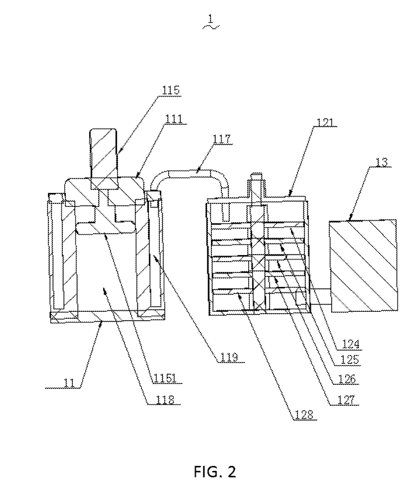
[0010] As shown in FIG. 1 to FIG. 3, the present disclosure of a sewage treatment device 1 comprises a compression tank 11 that is cylinderically shaped, a stirring structure 12 communicated with the compression tank 11 by a first intermediate pipe 117, and a detection box 13 communicated with the stirring structure 12 by a second intermediate pipe. A telescopic driving cylinder 115 is arranged on an upper portion of the compression tank 11. A conveying pipe 111 is connected with a top surface of the compression tank 11 to deliver external sewage to an interior of the compression tank 11. A diameter of the conveying pipe 111 ranges from 8-15 cm. A filter interlayer is arranged in the interior of the compression tank 11 and the filter interlayer is annular. An end of a driving shaft of the telescopic drive cylinder 115 is connected with a compression body 1151. An outer periphery of the compression body 1151 is contacted with an inner wall of the filter interlayer. The compressed body 1151 is made of silicone and has a thickness in a range of 7-12 cm. The filter interlayer comprises a sponge filter layer, an activated carbon filter layer, and a polyvinyl chloride (PVC) filter layer. The activated carbon filter layer is greater than the sponge filter layer and the PVC filter layer in thickness. The activated carbon filter layer ranges from 3-5 cm in thickness. The sponge filter layer, the activated carbon filter layer, and the PVC filter layer defining a plurality of filter holes where the filter holes are configured to filter sewage. The filter holes of the sponge filter layer, the filter holes of the activated carbon filter layer and the filter holes of the PVC filter layer are gradually reduced in aperture. Each of the filter holes of the sponge filter layer ranges from 0.3-0.6 mm in aperture. An end of the first intermediate pipe 117 extends into a portion 119 arranged between the interior portion of the compression tank 11 and the filter interlayer. Sewage compressed by the compression body 1151 is filtered by the filter interlayer from the interior portion of the compression tank 11 to the portion 119 arranged between the interior portion of the compression tank 11 and the filter interlayer, and then transported to the stirring structure 12 by the first intermediate pipe 117. A rotating shaft and a plurality of filter plates connected with the rotating shaft are arranged inside the stirring structure 12. A plurality of filter plates comprise a quartz sand filter plate 124, a cobble filter plate 125, an anthracite filter plate 126, an activated carbon filter plate 127 and a fiber filter plate 128. The quartz sand filter plate 124, the cobble filter plate 125, the anthracite filter plate 126, the activated carbon filter plate 127 and the fiber filter plate 128 are sequentially reduced in thickness. The quartz sand filter plate 124 ranges from 7.1-6.9 cm in thickness. The cobble filter plate 125 ranges from 5.8-6.7 cm in thickness. The anthracite filter plate 126 ranges from 4.9-5.5 cm in thickness. The activated carbon filter plate 127 ranges from 4.3-4.8 cm in thickness. The fiber filter plate 128 ranges from 3.3-4.2 cm in thickness.
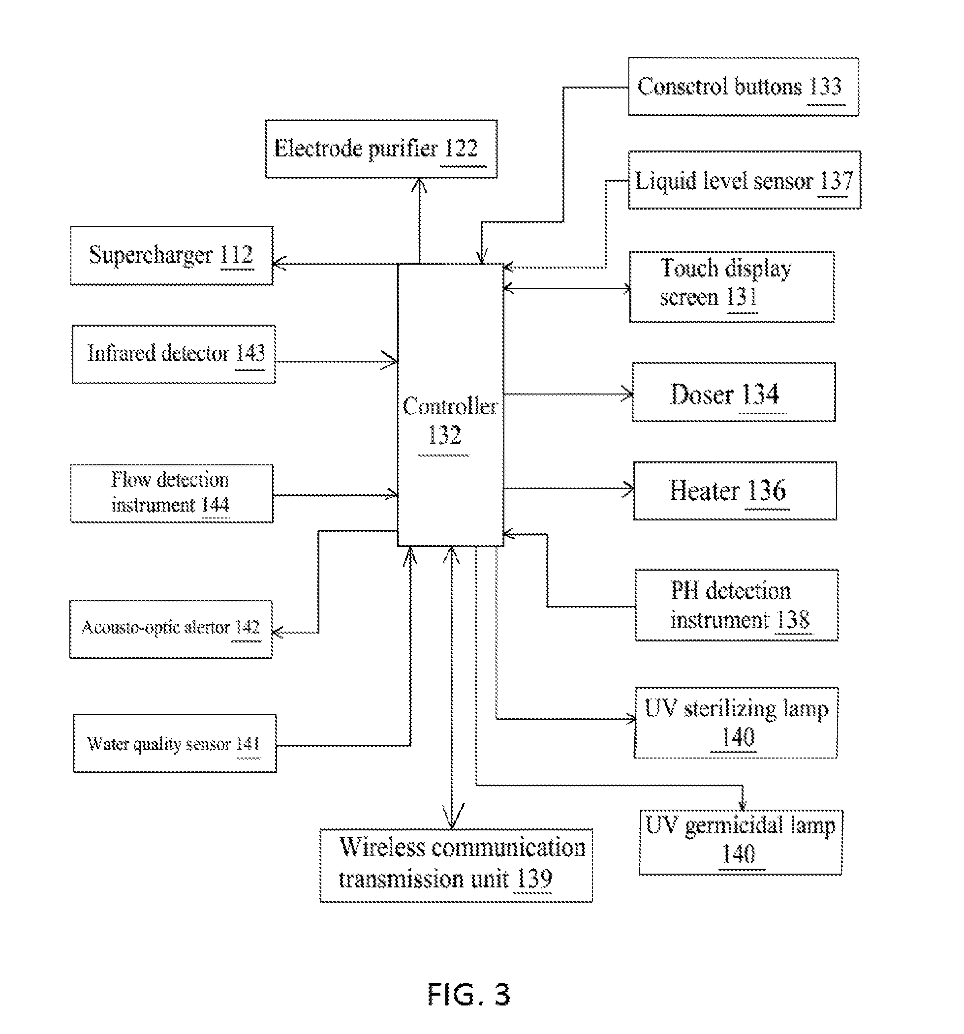
[0011] The sewage treatment device 1 further comprises a driving motor 123 configured to drive the rotary shaft to rotate. A cross support frame 121 is arranged on an upper portion of the stirring structure 12. The driving motor 123 is directly mounted on an upper portion of the cross support frame 121. A controller 132, a doser 134, a heater 136, a liquid level sensor 137, a PH detection instrument 138, a wireless communication transmission unit 139, an ultraviolet (UV) sterilizing lamp 140, an UV germicidal lamp 145 and a water quality sensor 141 are arranged inside the detection box 13. The doser 134, the heater 136, the liquid level sensor 137, the PH detection instrument 138, the wireless communication transmission unit 139, the UV sterilizing lamp 140, the UV germicidal lamp 145, and the water quality sensor 141 are electrically connected with the controller 132. A touch display screen 131, a plurality of control buttons 133 and a faucet are arranged on an exterior portion of the detection box 13. A flow detection instrument 144 is arranged on the faucet. An acousto-optic alertor 142 and an infrared detector 143 are arranged on the exterior portion of the detection box 13. The touch display screen 131, the control buttons 133, the flow detection instrument 144, the acousto-optic alertor 142, and the infrared detector 143 are electrically connected with the controller 132.
[0012] The present disclosure of the sewage treatment device 1 comprises the compression tank 11 that is cylinderically shaped, the stirring structure 12 communicated with the compression tank 11 by the first intermediate pipe 117, and the detection box 13 communicated with the stirring structure 12 by the second intermediate pipe. The filter interlayer is arranged in the interior of the compression tank 11 and the filter interlayer is annular. An end of the driving shaft of the telescopic drive cylinder 115 is connected with the compression body 1151. The outer periphery of the compression body 1151 is contacted with the inner wall of the filter interlayer. By extrusions and compression of the compressed body 1151, the sewage is filtered by a plurality of filter plates, and the stirring structure 12 is able to further purify the sewage to improve the treatment efficiency. The sewage treatment device 1 is reasonable in system structure design, low in production cost, and good in use effect. The sewage treatment device is suitable for a wide range of promotion.
[0013] Furthermore, a supercharger 112 is arranged in the interior of the compression tank 11, and the supercharger 112 is electrically connected with the controller 132.
[0014] Furthermore, a cation resin exchange filter layer, an ozone disinfection filter layer and a calcium carbonate filter layer are arranged in the filter interlayer. The cation resin exchange filter layer ranges from 1.5-2.2 cm in thickness. The disinfection filter layer ranges from 1.3-2.3 cm in thickness. The calcium carbonate filter layer ranges from 1.3-2.5 cm in thickness.
[0015] Furthermore, an electrode purifier 122 electrically connected with the controller 132 is arranged inside the stirring structure 12.
[0016] Furthermore, the touch display screen 131 is a capacitive touch display screen.
[0017] Compared with the prior art, The present disclosure of the sewage treatment device 1 comprises compression tank 11 that is cylinderically shaped, the stirring structure 12 communicated with the compression tank 11 by the first intermediate pipe 117, and the detection box 13 communicated with the stirring structure 12 by the second intermediate pipe. The filter interlayer is arranged in the interior of the compression tank 11 and the filter interlayer is annular. An end of the driving shaft of the telescopic drive cylinder 115 is connected with the compression body 1151. The outer periphery of the compression body 1151 is contacted with the inner wall of the filter interlayer. By extrusions and compression of the compressed body 1151, the sewage is filtered by a plurality of filter plates, and the stirring structure 12 is able to further purify the sewage to improve the treatment efficiency. The sewage treatment device 1 is reasonable in system structure design, low in production cost, and good in use effect. The sewage treatment device is suitable for a wide range of promotion.
[0018] The above-described embodiments of the present disclosure are not to be construed as limiting the scope of the present disclosure. Any of the modifications, equivalent replacement, and improvement within the spirit and principle of the present disclosure should fall within the protection scope of the claim.
* * * * *
D00000
D00001
D00002
D00003
XML
uspto.report is an independent third-party trademark research tool that is not affiliated, endorsed, or sponsored by the United States Patent and Trademark Office (USPTO) or any other governmental organization. The information provided by uspto.report is based on publicly available data at the time of writing and is intended for informational purposes only.
While we strive to provide accurate and up-to-date information, we do not guarantee the accuracy, completeness, reliability, or suitability of the information displayed on this site. The use of this site is at your own risk. Any reliance you place on such information is therefore strictly at your own risk.
All official trademark data, including owner information, should be verified by visiting the official USPTO website at www.uspto.gov. This site is not intended to replace professional legal advice and should not be used as a substitute for consulting with a legal professional who is knowledgeable about trademark law.