Apparatus And Method For The Production Of Foods
STROHM; Kurt ; et al.
U.S. patent application number 16/277142 was filed with the patent office on 2019-08-15 for apparatus and method for the production of foods. The applicant listed for this patent is ALBERT HANDTMANN MASCHINENFABRIK GMBH & CO. KG. Invention is credited to Daniel BETTINGER, Wolfgang SCHRADER, Kurt STROHM.
| Application Number | 20190248519 16/277142 |
| Document ID | / |
| Family ID | 61231079 |
| Filed Date | 2019-08-15 |


| United States Patent Application | 20190248519 |
| Kind Code | A1 |
| STROHM; Kurt ; et al. | August 15, 2019 |
APPARATUS AND METHOD FOR THE PRODUCTION OF FOODS
Abstract
The invention relates to an apparatus and a method for the production of foods, in particular, a stuffing machine for the production of sausages, with a load circuit that generates a leakage current IA and with a filter, a frequency converter, a motor cable and a motor. The apparatus comprises a leakage current compensator with a device for detecting a leakage current and a device for generating a compensation current that is directed opposite to the leakage current and is superimposed with the leakage current, such that the leakage current is reduced, is in particular substantially eliminated.
| Inventors: | STROHM; Kurt; (Attenweiler, DE) ; BETTINGER; Daniel; (Maselheim, DE) ; SCHRADER; Wolfgang; (Biberach, DE) | ||||||||||
| Applicant: |
|
||||||||||
|---|---|---|---|---|---|---|---|---|---|---|---|
| Family ID: | 61231079 | ||||||||||
| Appl. No.: | 16/277142 | ||||||||||
| Filed: | February 15, 2019 |
| Current U.S. Class: | 1/1 |
| Current CPC Class: | A22C 5/00 20130101; A22C 11/02 20130101; A22C 7/00 20130101; A22C 15/00 20130101; B65B 31/02 20130101; B65B 25/001 20130101; B65B 57/10 20130101; A22C 11/00 20130101; A22C 17/00 20130101; B65B 3/34 20130101; A22C 9/00 20130101; B65B 31/04 20130101; B65B 3/18 20130101; A22C 18/00 20130101 |
| International Class: | B65B 3/18 20060101 B65B003/18; B65B 31/02 20060101 B65B031/02; B65B 25/00 20060101 B65B025/00; B65B 31/04 20060101 B65B031/04; B65B 57/10 20060101 B65B057/10; B65B 3/34 20060101 B65B003/34 |
Foreign Application Data
| Date | Code | Application Number |
|---|---|---|
| Feb 15, 2018 | EP | 18156940.1 |
Claims
1. An apparatus for the production of foods, comprising: a load circuit that generates a leakage current; an EMC filter; a frequency converter; a motor cable; a motor; a leakage current compensator with a device for detecting said leakage current; and a device for generating a compensation current that is directed opposite to said leakage current and is superimposed with said leakage current, such that said leakage current is reduced.
2. The apparatus according to claim 1, wherein said leakage current is substantially eliminated when superimposed with said compensation current.
3. The apparatus according to claim 1, wherein said compensation current is shifted in its phase relative to said leakage current by 180.degree. and has substantially a same amplitude as said leakage current.
4. The apparatus according to claim 1, wherein said device for generating said compensation current comprises an amplifier and a capacitor network via which said compensation current is supplied to individual phases of a multi-phase system.
5. The apparatus according to claim 4, wherein the individual phases of the multi-phase system comprises at least one of three phases of a three-phase system.
6. The apparatus according to claim 4, wherein said leakage current compensator is arranged between a ground fault interrupter and said EMC filter.
7. The apparatus according to claim 4, wherein said leakage current compensator is installed in a device upstream of said apparatus.
8. The apparatus according to claim 7, wherein said apparatus further comprises a plug connected to said leakage current compensator by way of an outlet.
9. The apparatus according to claim 8, wherein a power supply of said leakage current compensator is effected via a power supply of said apparatus.
10. The apparatus according to claim 8, wherein said apparatus further comprises a delay device configured such that said compensation current is superimposed in a time-delayed manner.
11. The apparatus according to claim 10, wherein said compensation current is superimposed in the time-delayed manner only when all phases of said plug have contacted when said apparatus is plugged in, and further wherein said delay device is optionally configured such that said capacitor network is switched on only when all phases of said plug have contacted when said apparatus is plugged in.
12. The apparatus according to claim 1, wherein said leakage current compensator is integrated into said apparatus and is supplied via a separate auxiliary power supply.
13. The apparatus according to claim 12, wherein said apparatus can be unplugged and is movable.
14. The apparatus according to claim 1, wherein said apparatus is at least one apparatus from the following group: a stuffing machine for the production of sausages, a clipper, a spooling unit, a driven suspension unit, a cutter, a separation unit, a grouping unit, a conveyor belt, a charging system, and a packaging machine for food products.
15. A method for the production of foods with an apparatus comprising a load circuit that generates a leakage current, the method comprising: detecting said leakage current during operation of said apparatus; generating, with a leakage current compensator, a compensation current directed opposite to said leakage current; and superimposing said compensation current onto said leakage current, whereby said leakage current is reduced and substantially eliminated.
16. The method according to claim 15, wherein said leakage current compensator comprises an amplifier and a capacitor network, the method further comprising switching on said compensation current via said capacitor network in a time-delayed manner, when said apparatus is plugged in and only when all phases of a plug of said apparatus have contacted when plugged in.
17. The method according to claim 16, wherein a power supply of said leakage current compensator is effected via a power supply of said apparatus, wherein said leakage current compensator is integrated into said apparatus and is supplied via a separate auxiliary power supply.
18. The method according to claim 17, wherein said apparatus is unplugged, moved to another production location, and plugged in again.
19. The method according to claim 17, wherein said leakage current compensator is arranged between a ground fault interrupter and an EMC filter of said apparatus.
20. The method according to claim 19, wherein said apparatus is supplied with voltage via a three-phase mains with three phases, further comprising: detecting a current in the three phases; feeding corresponding signals to an amplifier comprising an evaluation unit; determining, with the evaluation unit, a respective leakage current by subtraction; and generating, with the evaluation unit, a compensation current which is fed via a capacitor network to at least one of the three phases.
Description
CROSS REFERENCE TO RELATED APPLICATIONS
[0001] The present application claims priority to European Patent Application No. 18156940.1 entitled "APPARATUS AND METHOD FOR THE PRODUCTION OF FOODS", and filed on Feb. 15, 2018. The entire contents of the above-listed application are hereby incorporated by reference for all purposes.
TECHNICAL FIELD
[0002] The invention relates to an apparatus and a method for the production of foods from pasty or liquid masses, in particular a stuffing machine for sausage production.
BACKGROUND AND SUMMARY
[0003] Machines and equipment in food production, in particular stuffing machines, such as vacuum stuffing machines, spooling lines, clippers, etc., often use switch-mode power supplies and electronically commutated drives. In order to satisfy the legal requirements for electromagnetic compatibility (EMC), filter measures against electrical faults are necessary. These EMC filters cause leakage currents that can trigger ground fault interrupters (GFIs)--in particular where they serve operator protection. This makes operation at outlets with a ground fault interrupter for operator protection impossible. With a ground fault interrupter having higher tripping thresholds, however, the machines and buildings are only protected against fire. The machines and systems are therefore often either fixedly connected to the mains, equipped with an isolating transformer, or operated at special outlets without ground fault interrupters. Another option is to lead the leakage currents--possibly--to the neutral conductor. Operator protection is achieved by way of the grounding conductor (PE).
[0004] However, the aforementioned measures have significant drawbacks.
[0005] In particular in food production, compact and mobile machines are needed that can be employed in a flexible manner. This includes e.g., that the machines can easily be moved out of production areas to another location for cleaning purposes. Attachments, such as a spooling line, clippers, a suspension device, etc., are often used in a flexible manner in particular in filling lines, so that the individual machines must be movable for the production. This is not possible with fixedly connected machines.
[0006] Machines with a built-in isolating transformer become larger and heavier, which also hampers mobility--just like isolating transformers which are mounted in external housings and can be connected upstream of the machine. In the isolating transformations, the leakage currents and therefore also the insulation fault current remain on the secondary side of the transformer. The detection of whether a compensation current flows, however, can only be measured and detected by the ground fault interrupter on the primary side of the transformer. Therefore, no protection is ensured by the ground fault interrupter. Especially in wet rooms, however, this protection is highly desired. The placement and marking of special outlets which are not protected with ground fault interrupters also increase the complexity and reduces the flexibility and safety.
[0007] If the filter currents are to be dissipated via the neutral conductor, special filters and inverters are required. The leakage currents of the cable shields continue to dissipate through the grounding conductor because the shields can be connected to the neutral conductor. A separate neutral conductor is not present in all types of mains, so this solution cannot be employed worldwide. Furthermore, with more comprehensive EMC filtering (larger and oversized filters), the high-frequency leakage currents can be reduced. For example, more efficient EMC input filters can be used in combination with additional output filters, but at higher costs. Another drawback of this measure against leakage currents is the space problem that arises especially when retrofitting larger and additional filters.
[0008] The use of ground fault interrupters with a high tripping threshold is also conceivable, but involves considerable risks since the higher leakage currents cause shifts in the potential and the permissible contact voltage of at most of 50 VAC can be exceeded. In addition, damage to the individual components of the system is possible.
[0009] Starting from there, the present invention is based on the object of providing an improved apparatus and an improved method for food production which can be employed in a flexible manner and at the same time can be operated safely.
[0010] According to the invention, this object is satisfied with an apparatus and a method for the production of foods as described further herein.
[0011] The apparatus for the production of foods is, in particular, a stuffing machine for the production of sausages with a load circuit that generates a leakage current. The apparatus comprises a motor to drive, for example, the conveyor of a stuffing machine. In order to satisfy the legal requirements for electromagnetic compatibility, filter measures against electrical faults are required. The apparatus also comprises, in particular, a frequency converter. Due to this at least one filter and a cable to the motor, leakage currents can arise that could trigger a ground fault interrupter. For this reason, a leakage current compensator is provided according to the present invention with a device for detecting a leakage current and a device for generating a compensation current that is directed opposite to the leakage current and is superimposed with the leakage current, such that the leakage current is reduced, is in particular substantially eliminated. The leakage current is there at least reduced to the extent that it is below the threshold for triggering a GFI ground fault interrupter. The leakage current is optionally completely eliminated.
[0012] This entails the advantage that the currents cancel each other and the ground fault interrupter is no longer tripped due to increased leakage currents. Only insulation faults or dangerous body currents can be detected and lead to tripping, for example, a frequency range of 100 Hz to 300 kHz should be covered. The frequency range 50-60 Hz may not be compensated so that operator protection remains in effect. The invention has the advantage that full operator protection is ensured and the apparatus can nevertheless be moved since it does not have to be fixedly installed and no large and heavy isolating transformer needs to be integrated. This also entails, inter alia, better hygiene due to simplified cleaning of the machine and great flexibility with regard to the assembly of the individual machines of a stuffing line. The leakage current compensator is inexpensive and can also be easily retrofitted into existing machines. In comparison to isolating transformer, high energy efficiency arises. With the present invention, a wide voltage range can be covered such that the apparatus can be used worldwide. Insulation faults or device faults are detected 100% with upstream ground fault interrupters. With the present invention, currents up to 1 A can be compensated.
[0013] The compensation current can be shifted in its phase relative to the leakage current by 180.degree. and have substantially the same amplitude. The leakage current can then be completely compensated. Since it is sufficient to have the leakage current be below the threshold for triggering the ground fault interrupter, the leakage current can be e.g. at approx. 40% of the switching threshold of the ground fault interrupter. It is essential that the leakage current is e.g. lower than the trigger threshold.
[0014] The device for generating a compensation current advantageously comprises an amplifier and a capacitor network (as filter capacitors) via which the compensation current can be supplied to individual phases of a multi-phase system, in particular to at least one of the three phases, optionally all three phases of a three-phase system. For example, the current can be detected in all three phases and the leakage current of each phase can be determined by calculating the difference, and a respective compensation current is conducted to the corresponding phases in terms of symmetrical load distribution.
[0015] Advantageously, the compensation current generated by the amplifier is distributed to the three phases in such a manner that the leakage current is overall compensated or sufficiently reduced.
[0016] The leakage current compensator is optionally located between a ground fault interrupter (GFI) and the EMC filter, i.e. the EMC input filter. The leakage currents generated by the filter can then be compensated, but also other leakage currents generated in the load circuit by parasitic coupling, in particular due to long motor leads and/or a frequency converter.
[0017] According to one preferred embodiment, the leakage current compensator is installed in a device upstream of the apparatus. The apparatus comprises in particular a plug which is connectable to the leakage current compensator by way of an outlet, in particular an industrial outlet. The apparatus therefore then comprises this device which in turn can be connected via an outlet, in particular an industrial outlet, to the mains by way of a plug, in particular an industrial plug. This entails the advantage that the apparatuses can be flexibly plugged in at various locations and a respective device can be easily retrofitted. A respective upstream device could then also be used for various apparatuses. But it is also possible that the apparatus is fixedly connected to the upstream device by use of a cable, and then connectable to an outlet, in particular an industrial outlet, using a plug.
[0018] Power supply for the leakage current compensator, in particular the amplifier, can be effected with the power supply of the apparatus, i.e. via the mains voltage. For example, if the leakage current compensator is installed in the upstream device, there may be a problem that the ground fault interrupter trips when this device is plugged into the industrial outlet. This is for the reason that the phases do not contact exactly at the same time during the plug-in action and asymmetric charging currents then arise through the Y-capacitors which can trigger the upstream GFI. In order to prevent this, the apparatus comprises a delay device which is configured in such a manner that the compensation current is superimposed with a time delay, i.e. in particular only when all the phases of the plug have contacted when the apparatus is connected to the mains. This means that the capacitor network is switched on optionally only when all phases of the plug have contacted when the apparatus is plugged in. The delay circuit can there be formed, for example, as a switching relay, a semiconductor relay, a time relay or as a software solution, or be implemented in the form of a mechanical solution in that the power supply for the compensation device is effected by way of plug contacts in a plug which, when plugged together, are located farther back than the contacts for the power supply of the apparatus, so that the contacts of the compensation device only contact after the power contacts have already contacted.
[0019] It is also possible that the leakage current compensator is integrated in the apparatus and is supplied by a separate auxiliary power supply, so that the leakage current compensator is already supplied before a leakage current is generated in the load circuit when the apparatus is switched on. It is advantageous and space-saving to have the leakage current compensator be integrated into the machine. No extra space outside the machine is then required if the leakage current compensator is integrated into the machine, it would be possible that the ground fault interrupter (GFI) triggers unintentionally if leakage currents already arise once the apparatus is switched on, but the compensator is not yet operational. To prevent this, the leakage current compensator is supplied with the separate auxiliary voltage that is applied before the load circuit generates the leakage current. The system can then compensate the current before the ground fault interrupter triggers. In this solution, it is no longer harmful if the phases of the load circuits are switched on in a non-symmetric manner. Therefore, no expensive protection with contacts contacting simultaneously is required.
[0020] As already described above, the present invention enables the apparatus to be disconnected and therefore be movable. If the apparatus comprises the external device with the leakage current compensator, this device has a mains plug.
[0021] The apparatus is advantageously an apparatus of at least a group: stuffing machine, clipper, spooling unit, driven suspension unit, cutter, separation unit, grouping unit, conveyor belt, charging system, packaging machine for food products, etc.
[0022] In the method according to the invention for the production of foods, in particular with the apparatus for the production of foods described herein including a load circuit generating a leakage current, the leakage current is detected during operation of the apparatus and a compensation current directed opposite to the leakage current is generated using a leakage current compensator. The compensation current is superimposed onto the leakage current, whereby the leakage current is reduced, in particular substantially eliminated.
[0023] The leakage current compensator comprises an amplifier and a capacitor network. When the apparatus is plugged in, the compensation current is advantageously switched on via the capacitor network with a time delay only when all the phases of a plug of the apparatus have been contacted during the plug-in action, i.e., are connected to the mains.
[0024] It is also possible that the power supply of the leakage current compensator is effected via the power supply of the apparatus or that the leakage current compensator is integrated into the apparatus and supplied by a separate auxiliary power supply such that the compensation current is already applied before a leakage current is generated in the load circuit. The system can then compensate the current before the ground fault interrupter triggers.
[0025] According to the present invention, the apparatus can therefore now be unplugged, i.e. be disconnected from the mains by way of a mains plug, be moved to another production location, and finally plugged in again. This enables increased flexibility while maintaining safety.
[0026] The leakage current compensator is advantageously located between a ground fault interrupter and an EMC filter. When the leakage current compensator is located upstream of the EMC input filter, all the leakage currents of the load circuit can be compensated.
[0027] It is particularly advantageous if the apparatus is supplied with power via three-phase mains and the current is detected in the three phases and the leakage current is determined by subtraction, corresponding signals are fed to an amplifier, comprising an evaluation unit, for generating a compensation current which is fed via a capacitor network to at least one, optionally all three phases, whereby the leakage current is substantially eliminated.
BRIEF DESCRIPTION OF THE FIGURES
[0028] FIG. 1 shows a simplified schematic representation of an apparatus according to the invention with a leakage current compensator;
[0029] FIG. 2 shows a simplified schematic representation of an embodiment of an apparatus according to the invention with an external leakage current compensator;
[0030] FIG. 3 shows a simplified schematic representation of an equivalent circuit diagram of a leakage current compensator for the embodiment shown in FIG. 2;
[0031] FIG. 4 shows a simplified schematic representation of a further embodiment of the present invention with an integrated leakage current compensator;
[0032] FIG. 5 shows a simplified schematic representation of an equivalent circuit diagram of a leakage current compensator for the embodiment shown in FIG. 4;
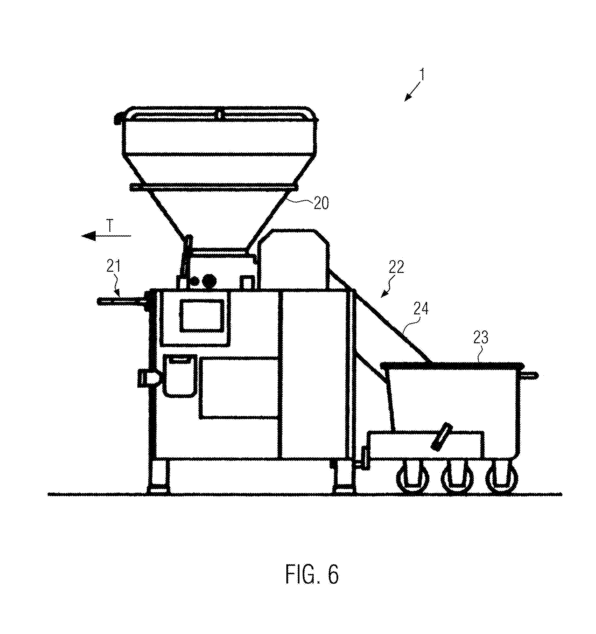
[0033] FIG. 6 shows a simplified schematic representation of a stuffing machine according to the present invention; and
[0034] FIG. 7 shows a further embodiment according to the present invention.
DETAILED DESCRIPTION
[0035] FIG. 6 shows a simplified schematic representation of an apparatus 1 for the production of foods, presently in the form of a stuffing machine 1. Stuffing machine 1 comprises a hopper 20 into which the pasty substance, e.g. sausage meat, is filled and passes downwardly into a conveying mechanism, no shown, for example, into a rotary vane pump, via which it is ejected into a stuffing tube 21, for example, into a sausage casing, not shown. The apparatus can also comprise, for example, a lifting device 22 which raises a sausage meat carriage 23 upwardly by way of a lifting arm 24 and empties it into hopper 20. The stuffing machine can comprise a motor 2, as shall be explained below, which drives, for example, the conveying mechanism. The stuffing machine can further comprise a separate motor for lifting device 22.
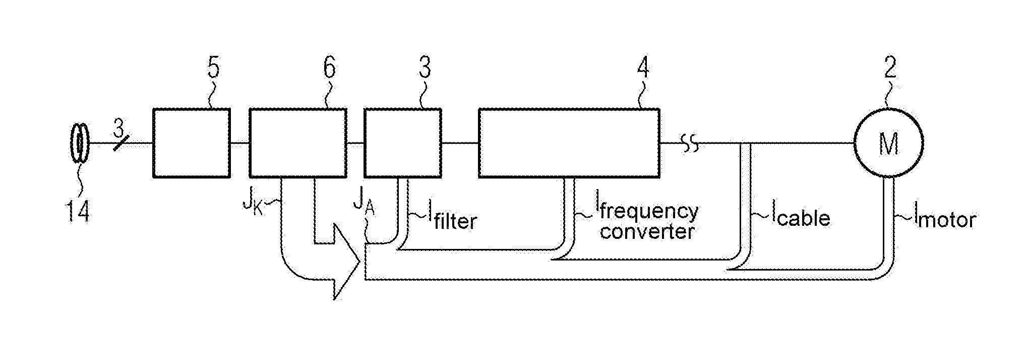
[0036] FIG. 1 shows a simplified schematic representation of a load circuit for motor 2. FIG. 1 shows a simplified schematic representation of a drive system, for example, for a rotary vane pump, which substantially comprises an EMC input filter 3, a frequency converter 4, a motor cable 5 and a motor 2. The EMC filter as well as frequency converter 4 and the long motor cable and motor 2 can produce leakage currents that would trigger a ground fault interrupter 5. According to the present invention, a leakage current compensator 6 is provided upstream of EMC filter 3 and generates a compensation current I.sub.K, which is directed opposite to leakage current I.sub.A. The leakage current can thus be compensated, i.e. be eliminated, at least be reduced so that it is below the threshold for triggering GFI ground fault interrupter 5, for example, below the tripping threshold of 30 mA for currents in the frequency range <100 Hz, of 300 mA for currents with a frequency >1000 Hz.
[0037] Leakage current I.sub.A is the sum of all individual present leakage currents, the sum of I.sub.Filter+I.sub.Frequency-coverter+I.sub.Cabel+I.sub.Motor. According to the present invention, a frequency range between 100 Hz and 300 kHz is to be covered. The frequency range of 50 to 60 Hz may not be compensated so that operator protection remains in effect. In practice, compensation currents up to 1 A are required. Compensation current I.sub.K is optionally shifted in its phase by 180.degree. relative to leakage current I.sub.A and has substantially the same amplitude and optionally the same frequency.
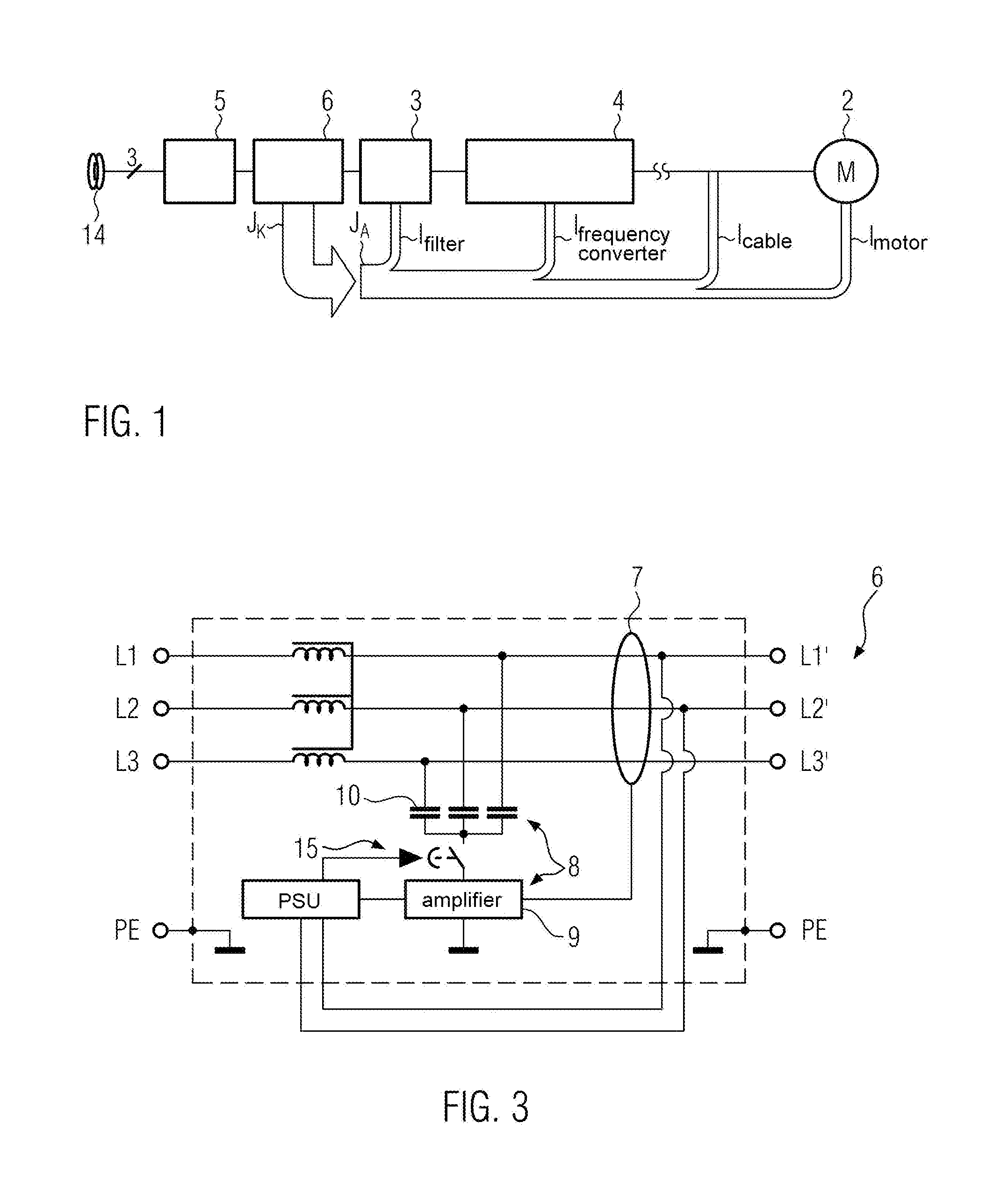
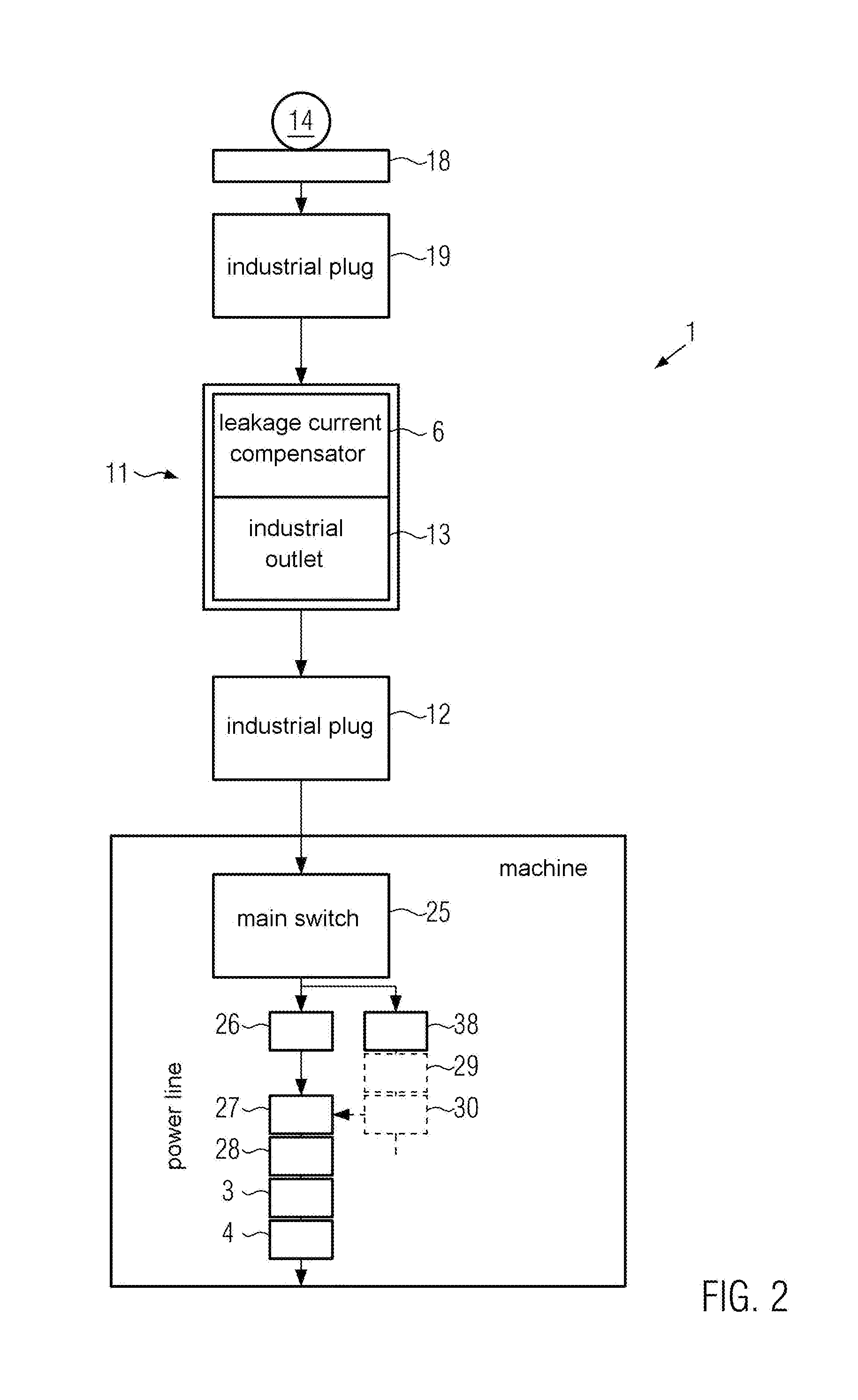
[0038] FIG. 2 shows an embodiment according to the present invention with an external leakage current compensator 6 arranged outside of the machine housing. FIG. 2 shows a power supply 14, for example, three-phase mains, as well as an industrial outlet 18 via which an apparatus with a mains plug 19 can be plugged on. In this embodiment, leakage current compensator 6 is installed in an upstream device 11 which comprises a further industrial outlet 13 into which an industrial plug 12 of apparatus 1 can in turn be plugged. Industrial plug 12 is connected via a corresponding line to main switch 25 of the apparatus. A motor protection switch 26 can be provided thereafter, and a main contactor 27 without "symmetrical contacts", i.e. without snap-action contacts. Thereafter, a mains line choke 28 can be provided, followed by an EMC filter 3 and a frequency converter from which motor 2 can be supplied. After main switch 25, a line can branch off to a transformer protection switch 38 which is connected to a control transformer 29 and supplies a control unit 30. Control unit 30 is connected to the main contactor in order to switch on the main contactor. As shown in FIG. 2, leakage current compensator 6 is supplied with power in the same load circuit as the motor by way of power supply 14 i.e. the mains voltage. The leakage current compensator is therefore located upstream of main switch 25.
[0039] FIG. 3 shows an equivalent circuit diagram of leakage current compensator 6 for the embodiment shown in FIG. 2. FIG. 3 shows three-phase mains. Leakage current compensator 6 comprises a device for measuring a leakage current 7 as well as a device for generating a compensation current 8. The device for generating a compensation current 8 comprises an amplifier 9 which is connected to the device for measuring the leakage current 7 and comprises an evaluation unit which can determine a leakage current I.sub.A and a compensation current I.sub.K on the basis of the values measured. The device for detecting a leakage current 7 can comprise, for example, a measuring caliper. The currents of the three phases can be detected, and the leakage current from the respective differences. This means that, if the sum of the currents in the three phases L1, L2, L3 is not 0, a leakage current I.sub.A is present. Compensation current I.sub.K is calculated e.g. such that it is shifted in its phase by 180.degree. relative to leakage current I.sub.A and has substantially the same amplitude as the leakage current. FIG. 3 shows in a simplified representation that amplifier 9 feeds the compensation current to the three phases based on compensation current I.sub.K determined such that the sum of the currents of the individual phases L1, L2, L3 is e.g. again 0 and the leakage current is thus compensated, is at least located below a triggering threshold of the GFI switch.
[0040] For example, the respective current I.sub.L1, I.sub.L2, I.sub.L3 can there be measured.
[0041] For example, a leakage current and an opposite compensation current, which is then distributed to the three phases L1, L2, L3, are determined by subtraction.
[0042] However, it is also possible to determine a separate leakage current for each phase by measuring the currents in each individual phase and to then determine corresponding compensation currents for the individual phases and to supply them accordingly to each phase.
[0043] In this embodiment, the leakage current compensator is supplied with power from power supply 14 via two of the phases of the three-phase system, as already explained.
[0044] The apparatus advantageously comprises a delay device 15. Delay device 15 is configured such that compensation current I.sub.K is superimposed with a time delay, in particular only when all phases of plug 19 have contacted when the apparatus is plugged in. This means that capacitor network 10 is switched on only when all phases of the plug have contacted when the apparatus is plugged in. It can thus be prevented that the GFI can already trigger when apparatus 1 is plugged in. This problem arises from the fact that phases L1, L2, L3 do not contact at exactly the same time and asymmetric charging currents then arise through the Y-capacitors of capacitor network 10 which can trigger the upstream GFI. This can be prevented by delay circuit 15. Delay circuit 15 can be implemented, for example, as a time relay, a semiconductor relay, or as a software solution. Furthermore, there is also the possibility of a mechanical delay device 15, such that leakage current compensator 6 is supplied with power in a time delayed manner, for example, in that plug 19 is configured such that the contacts supplying leakage current compensator 6 with power are located further back so they only contact after the power contacts have already contacted. This can be realized, for example, by shorter pins.
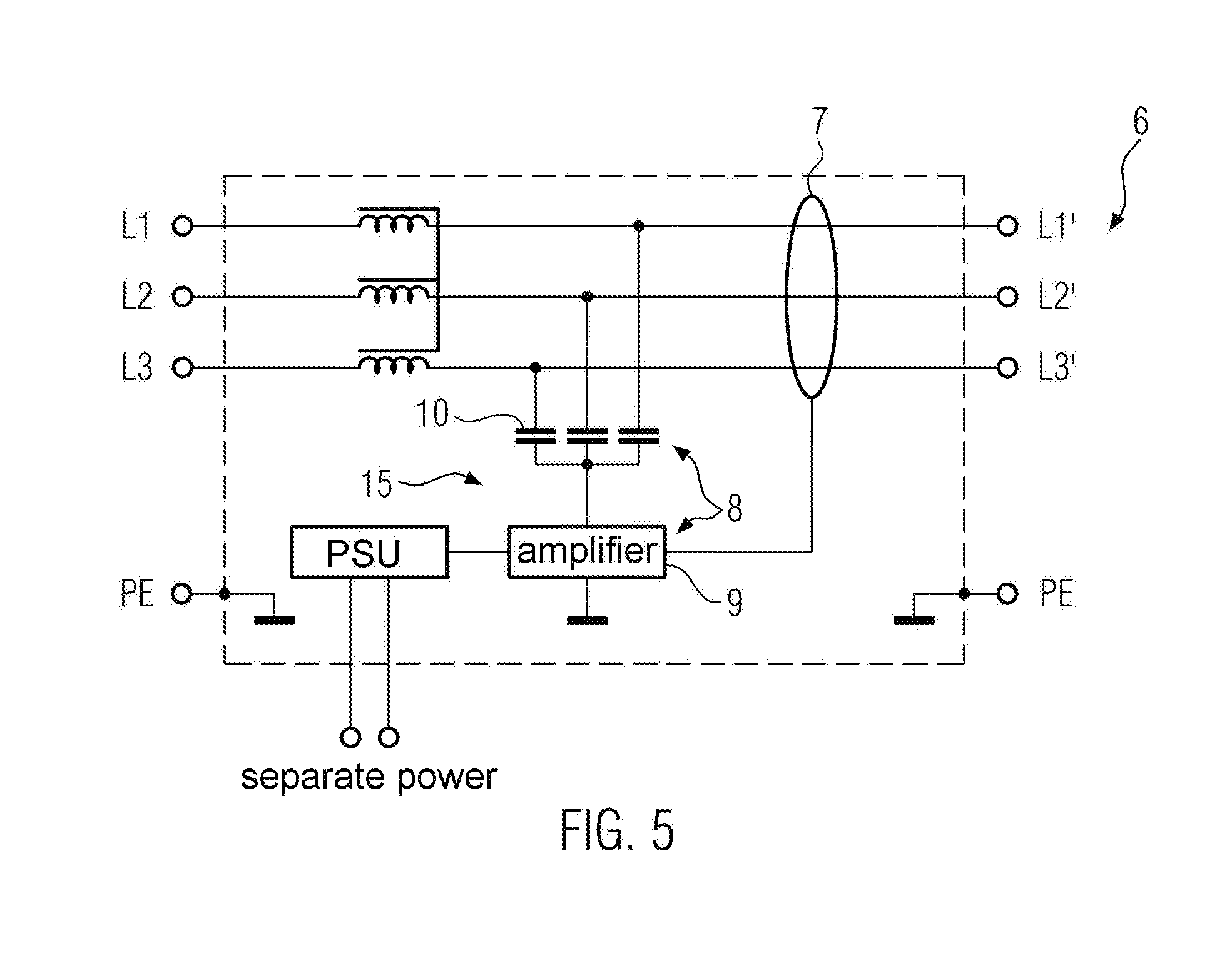
[0045] FIG. 4 shows a further embodiment according to the present invention. Leakage current compensator 6 is there installed directly into the apparatus i.e. is integrated. As can be seen, leakage current compensator 6 is located between industrial plug 12 and EMC mains filter 3. In order to here as well prevent that the GFI ground fault interrupter triggers unintentionally, leakage current compensator 6 is supplied with a separate auxiliary voltage 16 and not via mains voltage 14 like in the first embodiment. Different separate auxiliary power supplies 16 can there be used. In the embodiment shown in FIG. 4, for example, current is branched off downstream of the main switch to a circuit breaker for transformers and supplied to leakage current compensator 6. This avoids the problem that the GFI triggers unintentionally when leakage currents already arise once the machine is switched on but the compensator is not yet ready for operation. To prevent this, the compensator is supplied the separate auxiliary voltage that is applied before the load circuits generate the leakage current. The system can then compensate leakage current I.sub.A before the GFI ground fault interrupter triggers. In this solution, it is no longer harmful if the phases of the load circuits are switched on in a non-symmetric manner. Therefore, no expensive protection with contacts contacting simultaneously is required.
[0046] FIG. 7 shows a further embodiment according to the present invention. The embodiment shown in FIG. 7 corresponds to the embodiment shown in FIG. 4. In this embodiment, multiple motors are present in the apparatus. This means that a further motor for another functional unit, for example for a lifting device and/or a spooling device are provided in a stuffing machine, in addition to a motor for the rotary vane pump. According to a first alternative, for example, a further frequency converter for further motor 2 can be provided downstream of the EMC mains filter and/or downstream of the mains line choke and a further frequency converter can be provided for a further motor. These load circuits can therefore be protected as well, i.e. several motors by only one leakage current compensator 6.
LIST OF REFERENCE NUMERALS
[0047] 1 apparatus [0048] 2 motor [0049] 3 EMC filter [0050] 4 frequency converter [0051] 5 ground fault interrupter [0052] 6 leakage current compensator [0053] 7 device for measuring leakage current [0054] 8 device for generating a compensation current [0055] 9 amplifier [0056] 10 capacitor network [0057] 11 upstream device [0058] 12 plug [0059] 13 outlet [0060] 14 power supply [0061] 15 delay device [0062] 16 separate power supply
* * * * *
D00000
D00001
D00002
D00003
D00004
D00005
D00006
XML
uspto.report is an independent third-party trademark research tool that is not affiliated, endorsed, or sponsored by the United States Patent and Trademark Office (USPTO) or any other governmental organization. The information provided by uspto.report is based on publicly available data at the time of writing and is intended for informational purposes only.
While we strive to provide accurate and up-to-date information, we do not guarantee the accuracy, completeness, reliability, or suitability of the information displayed on this site. The use of this site is at your own risk. Any reliance you place on such information is therefore strictly at your own risk.
All official trademark data, including owner information, should be verified by visiting the official USPTO website at www.uspto.gov. This site is not intended to replace professional legal advice and should not be used as a substitute for consulting with a legal professional who is knowledgeable about trademark law.