Toy Projectile Launching Figurine
Chuang; Peter ; et al.
U.S. patent application number 15/896462 was filed with the patent office on 2019-08-15 for toy projectile launching figurine. The applicant listed for this patent is Mattel, Inc.. Invention is credited to Peter Chuang, Steve P. Dunham.
| Application Number | 20190247762 15/896462 |
| Document ID | / |
| Family ID | 67541896 |
| Filed Date | 2019-08-15 |


| United States Patent Application | 20190247762 |
| Kind Code | A1 |
| Chuang; Peter ; et al. | August 15, 2019 |
Toy Projectile Launching Figurine
Abstract
A toy figurine comprising a projectile and an appendage pivotable along a range of positions. The pivotable appendage comprises a projectile launching unit having a catch for releasably engaging the projectile and a biasing member for providing a propulsion force to the engaged projectile. Pivoting the appendage to a launch position causes a joint to trigger the catch and release the engaged projectile, thereby allowing the biasing member to launch the engaged projectile.
| Inventors: | Chuang; Peter; (Irvine, CA) ; Dunham; Steve P.; (Westchester, CA) | ||||||||||
| Applicant: |
|
||||||||||
|---|---|---|---|---|---|---|---|---|---|---|---|
| Family ID: | 67541896 | ||||||||||
| Appl. No.: | 15/896462 | ||||||||||
| Filed: | February 14, 2018 |
| Current U.S. Class: | 1/1 |
| Current CPC Class: | A63H 3/46 20130101; A63H 13/10 20130101 |
| International Class: | A63H 13/10 20060101 A63H013/10; A63H 3/46 20060101 A63H003/46 |
Claims
1. A toy figurine comprising: a torso; a first arm portion coupled to the torso; a second arm portion pivotally coupled to the first arm portion, the second arm portion being movable relative to the first arm portion between a cocked position and a launch position, the second arm portion including: a wall defining a cavity; an opening in communication with the cavity; and a release mechanism disposed in the cavity, the release mechanism comprising a biasing member and a catch; wherein the release mechanism is activated by movement of the second arm portion from the cocked position to the launch position, and activation of the release mechanism results in the catch moving and allowing the biasing member to force a projectile away from the opening; and a joint positioned between the first arm portion and the second arm portion, wherein the second arm portion pivots about the joint when moving between the cocked position and the launch position, the joint including a circular portion having a protrusion that activates the release mechanism when the second arm portion is moved to the launch position.
2. (canceled)
3. The toy figurine of claim 1, wherein the second arm portion further comprises an actuator operatively positioned between the joint and release mechanism and wherein the protrusion of the joint moves the actuator to activate the release mechanism.
4. The toy figurine of claim 1, further comprising a torsion spring for biasing the second arm portion to the cocked position.
5. The toy figurine of claim 1, further comprising a catch spring for biasing the catch to a retaining position.
6. The toy figurine of claim 1, further comprising a projectile having an elongated member and a notch on the elongated member for engaging with the catch.
7. The toy figurine of claim 6, wherein a portion of the elongated member is sized to fit within the biasing member and the projectile compresses the biasing member when the elongated member is engaged with the catch.
8. The toy figurine of claim 1, wherein the first arm portion and the second arm portion form a substantially straight line when the second arm portion is pivoted to the launch position.
9. A toy projectile launching figurine comprising: a projectile; and an appendage pivotable about a joint along a range of positions including a launch position, the pivotable appendage comprising a projectile launching unit configured to: engage the projectile; and launch the engaged projectile when the appendage is pivoted to the launch position; wherein the joint includes a circular portion having a protrusion and pivoting the appendage to the launch position causes the protrusion to activate the projectile launching unit and launch the engaged projectile.
10. The toy projectile launching figurine of claim 9, wherein the projectile launching unit comprises: a catch for releasably engaging the projectile; and a propulsion spring for providing a propulsion force to the engaged projectile.
11. The toy projectile launching figurine of claim 10, wherein pivoting the appendage to the launch position causes the protrusion of the joint to trigger the catch and release the engaged projectile.
12. The toy projectile launching figurine of claim 11, wherein the appendage further comprises an actuator operatively positioned between the joint and catch and wherein the protrusion of the joint pushes the actuator to trigger the catch.
13. The toy projectile launching figurine of claim 9, further comprising a torsion spring for biasing the appendage away from the launch position.
14. The toy projectile launching figurine of claim 10, further comprising a catch spring for biasing the catch to a retaining position.
15. The toy projectile launching figurine of claim 10, wherein the projectile comprises an elongated member having an engagement portion for engaging with the catch.
16. The toy projectile launching figurine of claim 15, wherein a portion of the elongated member is sized to fit within the propulsion spring and the projectile compresses the propulsion spring when the elongated member is engaged with the catch.
17. The toy projectile launching figurine of claim 10, wherein the pivotable appendage is a portion of an arm and the joint is an elbow joint.
18. The toy projectile launching figurine of claim 17, wherein the projectile is launched when the arm is straightened.
19. A toy figurine comprising: a projectile; and a pivotable arm portion that pivots about an elbow joint, the pivotable arm portion comprising a projectile launching unit having a catch for releasably engaging the projectile and a biasing member for providing a propulsion force to the engaged projectile; wherein the elbow joint includes a circular portion having a protrusion and pivoting the pivotable arm portion to a launch position causes the protrusion of the elbow joint to trigger the catch and allow the biasing member to launch the engaged projectile.
20. The toy figurine of claim 19, wherein the pivotable arm portion further comprises an actuator operatively positioned between the elbow joint and catch and wherein the protrusion of the elbow joint pushes the actuator to trigger the catch.
Description
FIELD OF THE INVENTION
[0001] The present invention relates generally to toy figurines, and in particular toy figurines that launch or shoot projectiles.
BACKGROUND OF THE INVENTION
[0002] Toy figurines include action figures that model humans, animals, robots, aliens, and other real and fictional entities. To enhance the playability of these toy figurines, it is desirable for the toy figurine to have moving parts, such as an ability to launch or shoot projectiles. Additionally, it is desirable for the launching mechanism to be operated through an extension of the movement of the toy figurine for a more natural and engaging play activity. Therefore, there is a need for a toy figurine with a projectile launching feature that provides enhanced entertainment and play value.
SUMMARY OF THE INVENTION
[0003] The present invention provides a toy figurine having a projectile launching or shooting feature. Through the manual movement of an appendage of the toy figurine, a projectile launching mechanism forming part of the appendage is activated to launch a projectile. In an exemplary embodiment, an arm portion of a toy figurine comprises a projectile launching unit configured to engage and launch a projectile. When the arm portion is manually pivoted to a specific launch position in the course of playing with the toy figurine, the projectile launching unit is activated to launch the projectile. Such a projectile launching feature provides a more interesting and engaging play value to the toy figurine.
[0004] According to one aspect of the present invention, a toy figurine is provided. The toy figurine comprises a torso, a first arm portion coupled to the torso, and a second arm portion pivotally coupled to the first arm portion. The second arm portion is movable relative to the first arm portion between a cocked position and a launch position. The second arm portion includes a wall defining a cavity and an opening in communication with the cavity, a biasing member disposed in the cavity, a catch, and a release mechanism. A catch spring biases the catch to a retaining position. In one or more embodiments, the toy figurine further comprises a projectile having an elongated member and a notch on the elongated member for engaging with the catch. In a typical embodiment, a portion of the elongated member is sized to fit within the biasing member and the projectile compresses the biasing member when the elongated member is engaged with the catch.
[0005] The release mechanism is activated by moving the second arm portion from the cocked position to the launch position. Activation of the release mechanism results in movement of the catch, which allows the biasing member to force a projectile away from the opening. The second arm portion pivots about a joint. The joint activates the release mechanism when the second arm portion is pivoted to the launch position. In one instance, the first arm portion and the second arm portion form a substantially straight line when the second arm portion is pivoted to the launch position. In one or more embodiments, the second arm portion comprises an actuator operatively positioned between the joint and release mechanism. The joint moves the actuator to activate the release mechanism. In further embodiments, the toy figurine comprises a torsion spring for biasing the second arm portion to the cocked position.
[0006] According to another aspect of the present invention, a toy projectile launching figurine is provided. The toy projectile launching figurine comprises a projectile and an appendage pivotable along a range of positions including a launch position. The pivotable appendage comprises a projectile launching unit configured to engage the projectile and launch the engaged projectile when the appendage is pivoted to the launch position. The projectile launching unit comprises a catch for releasably engaging the projectile and a propulsion spring for providing a propulsion force to the engaged projectile. A catch spring biases the catch to a retaining position. In one or more embodiments, the projectile comprises an elongated member having an engagement portion for engaging with the catch. In a typical embodiment, a portion of the elongated member is sized to fit within the propulsion spring and the projectile compresses the propulsion spring when the elongated member is engaged with the catch.
[0007] The appendage pivots about a joint. Pivoting the appendage to the launch position causes the joint to trigger the catch and release the engaged projectile. In one or more embodiments, the pivotable appendage is a portion of an arm and the joint is an elbow joint. In one instance, the projectile is launched when the arm is straightened. In one or more embodiments, the appendage further comprises an actuator operatively positioned between the joint and catch. The joint pushes the actuator to trigger the catch. In further embodiments, the toy projectile launching figurine comprises a torsion spring for biasing the appendage away from the launch position.
[0008] According to another aspect of the present invention, a toy figurine is provided. The toy figurine comprises a projectile and a pivotable arm portion that pivots about an elbow joint. The pivotable arm portion comprises a projectile launching unit having a catch for releasably engaging the projectile and a biasing member for providing a propulsion force to the engaged projectile. Pivoting the pivotable arm portion to a launch position causes the elbow joint to trigger the catch and allow the biasing member to launch the engaged projectile. In one or more embodiments, the pivotable arm portion further comprises an actuator operatively positioned between the elbow joint and catch. The elbow joint pushes the actuator to trigger the catch.
[0009] Other objects, features and advantages of the present invention will become apparent to those skilled in the art from the following detailed description. It is to be understood, however, that the detailed description and specific examples, while indicating some embodiments of the invention, are given by way of illustration and not limitation. Many changes and modifications within the scope of the invention may be made without departing from the spirit thereof, and the present invention includes all such modifications.
BRIEF DESCRIPTION OF THE DRAWINGS
[0010] Referring now to the drawings in which like reference numbers represent corresponding parts throughout:
[0011] FIG. 1 illustrates an exploded view of a toy figurine in accordance with one embodiment of the invention;
[0012] FIG. 2 illustrates a front view of a toy figurine in accordance with another embodiment of the invention;
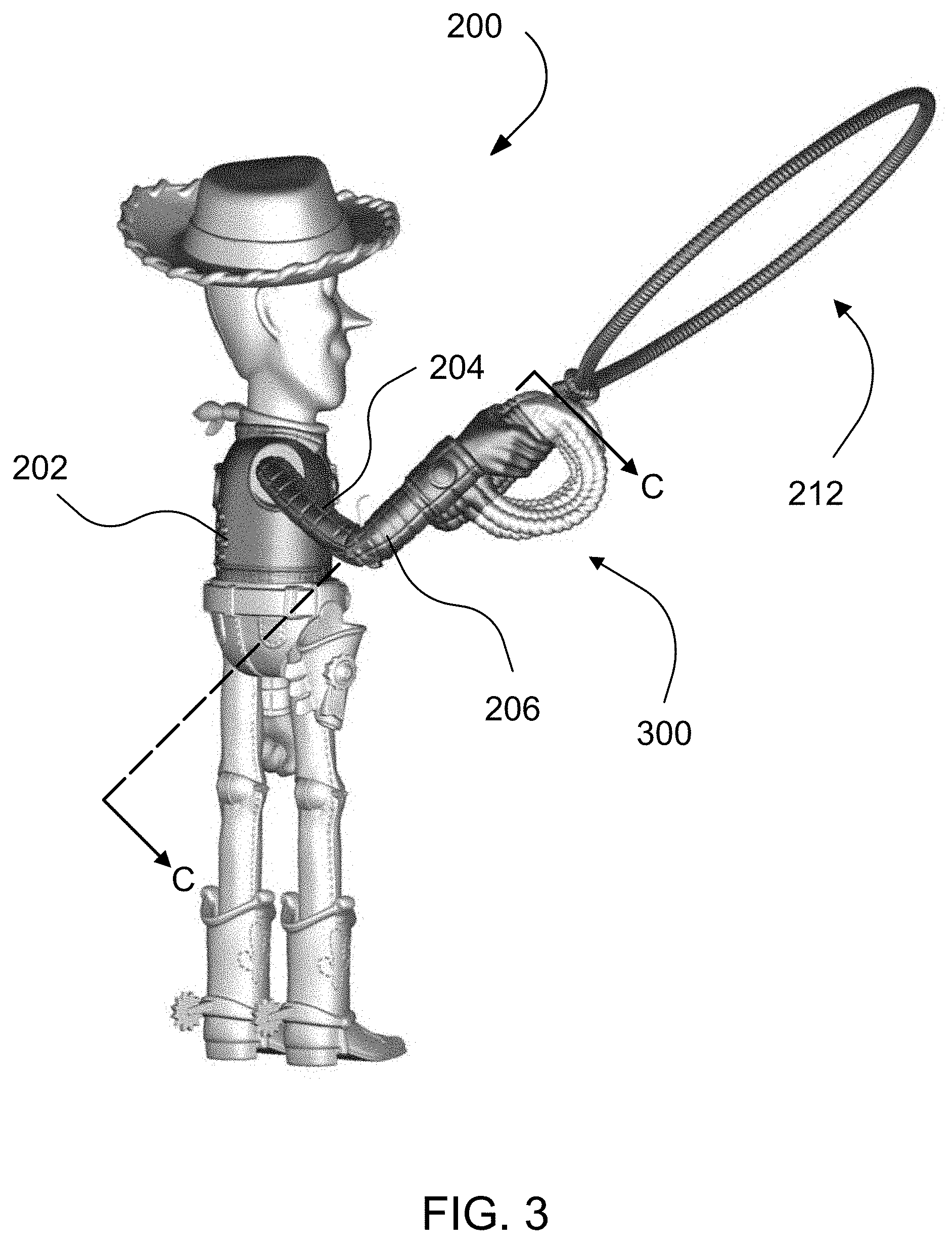
[0013] FIG. 3 illustrates a side view of the toy figurine of FIG. 2;
[0014] FIG. 4 illustrates a cross-sectional view of a projectile launching unit of the toy figurine of FIG. 3 along line C-C;
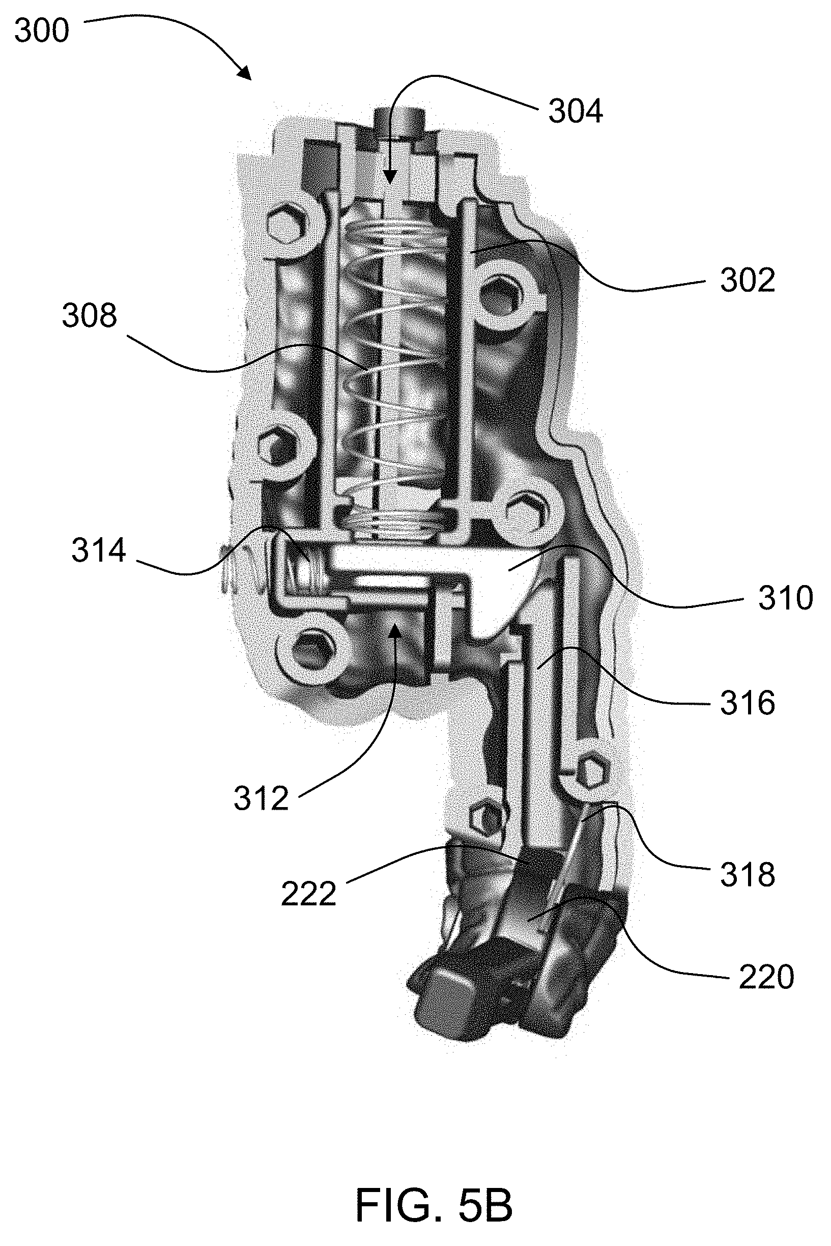
[0015] FIGS. 5A-5B illustrate cross-sectional views of the projectile launching unit of the toy figurine of FIG. 3 along line C-C with an engaged projectile (FIG. 5A) and without an engaged projectile (FIG. 5B); and
[0016] FIG. 6 illustrates an exploded view of the toy figurine of FIG. 2.
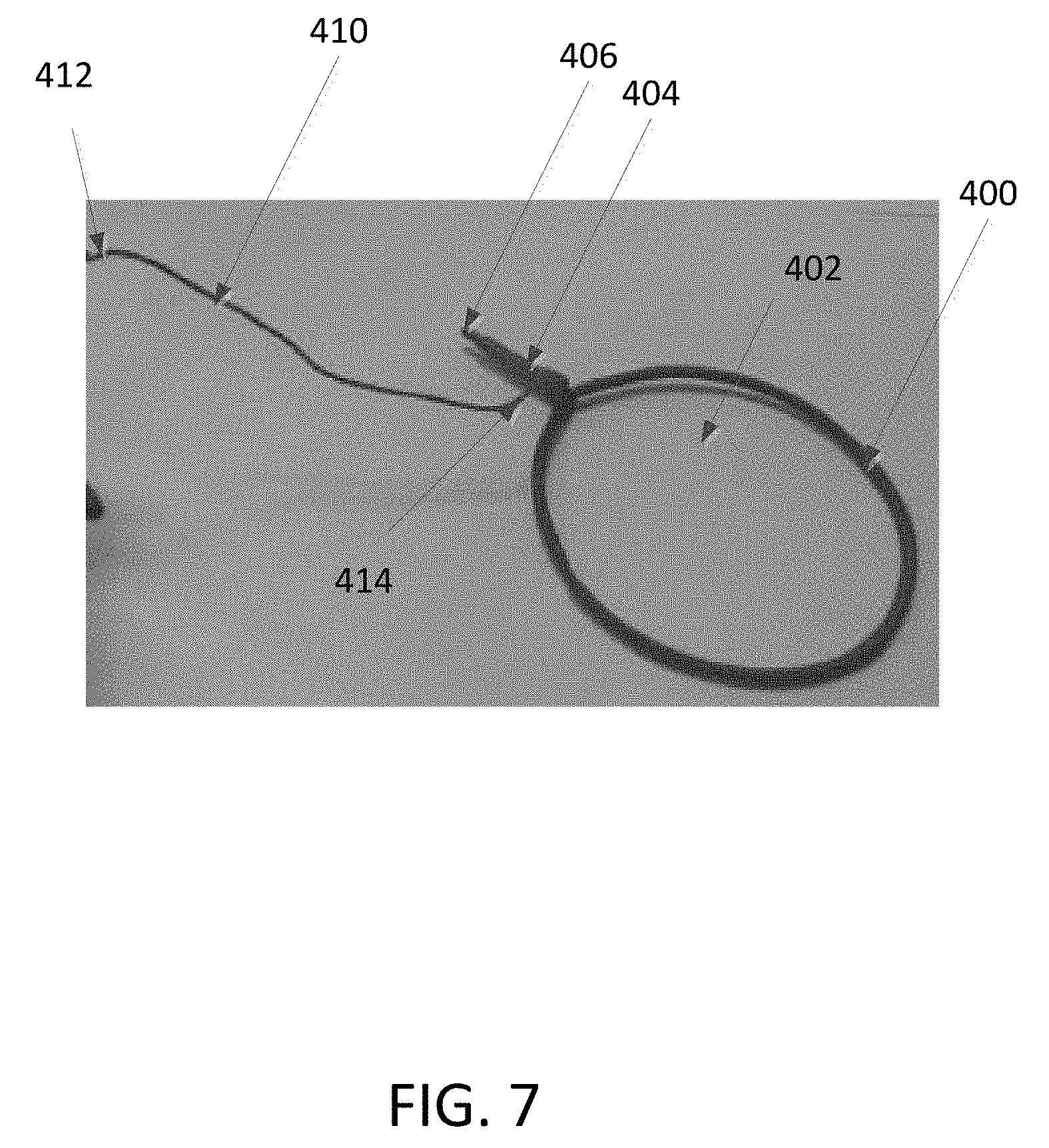
[0017] FIG. 7 illustrates a perspective view of an embodiment of a projectile according to the present invention.
DETAILED DESCRIPTION OF THE INVENTION
[0018] A toy figurine according to the present invention allows a user to easily and naturally launch projectiles during the course of play. As described herein, the toy figurine includes dolls, figures, models, and action figures that may be based on or model any real, fictional or fantasy character, object or entity. Generally, the toy figurine comprises a main body and one or more appendages movably connected to the body. The movable appendage may be a limb, body part, member, attachment or accessory movably connected to the body of the toy figurine. A projectile launching unit is connected to or forms a part of the movable appendage and imparts a projectile launching feature to the toy figurine. The projectile launching unit is activated to launch a projectile when the appendage is manually moved to a specific launch position. The appendage may be manually moved to the specific launch position, for example by pivoting, rotating, twisting, extending, or contracting the appendage. In some embodiments, the toy figurine has a plurality of movable appendages with each appendage having a separate projectile launching unit.
[0019] FIG. 1 shows an exploded view of a toy figurine 100 according to an embodiment of the present invention. In this embodiment, an arm 102 is movably connected to a torso 104 of the toy figurine 100. More specifically, the arm 102 is pivotable about an axis 115 on a shoulder region of the toy figurine 100. A projectile launching unit 106 is attached to the arm 102 and is configured to receive and launch a projectile 108. The projectile launching unit 106 has a cylindrical member 109 that defines a cavity 110 for receiving the projectile 108. A biasing member 112 is further disposed in the cavity 110. When the projectile 108 is inserted into the projectile launching unit 106, the projectile 108 compresses the biasing member 112. The compression and subsequent expansion of the biasing member 112 back to its original shape (discussed in further detail below) provides a propulsion force that launches the projectile 108 from the projectile launching unit 106.
[0020] The projectile launching unit 106 includes a catch 114 that releasably engages and retains the projectile 108 in the cylindrical member 109 until the projectile launching unit 106 is activated to launch the projectile 108. Activation of the projectile launching unit 106 is accomplished by moving the arm 102, which pivots in a range of positions around the axis 115 along the directions of arrow A (see FIG. 1). A joint 116 having a protrusion 118 is positioned coaxially with the arm 102. The arm 102 also includes an actuator 120 located between the joint 116 and catch 114. When the arm 102 is pivoted to a specific launch position, the protrusion 118 on the joint 116 moves the actuator 120 to trigger the catch 114. The catch 114 subsequently releases the projectile 108 and allows the projectile 108 to be launched from the projectile launching unit 106 by the biasing member 112. In some embodiments, the toy figurine has multiple launch positions. For example, the joint 116 may have multiple protrusions 118 so that the catch 114 is triggered when the arm 102 is pivoted to different launch positions.
[0021] FIGS. 2 and 3 show front and side views, respectively, of a toy figurine 200 according to another exemplary embodiment of the present invention. Toy figurine 200 comprises a torso 202, a first arm portion 204 coupled to the torso 202, and a second arm portion 206 pivotally coupled to the first arm portion 204. The second arm portion 206 comprises a projectile launching unit 300 (see FIG. 3) and is movable relative to the first arm portion 204 in a range of motion along the directions of arrow B between a cocked position 208 (see FIG. 2) and a launch position 210 (represented with line-shading in FIG. 2). As long as the second arm portion 206 is not in the launch position 210, such as in the cocked position 208, a projectile 212 can be inserted and retained in the second arm portion 206 of the toy figurine 200. As described in further detail below, the projectile 212 is launched from the second arm portion 206 when the second arm portion 206 is moved to the launch position 210. In this instance, the projectile 212 is launched by pivoting the second arm portion 206 to a position where the first arm portion 204 and the second arm portion 206 form a substantially straight line (i.e. the arm is straightened). The first arm portion 204 is also pivotable relative to the torso 202 to provide additional adjustability in the angle and/or direction that the projectile 212 is launched.
[0022] FIGS. 4 and 5A-5B provide detailed views of the projectile launching unit 300 and the release mechanism for launching a projectile according to one or more embodiments of the present invention. As shown in FIG. 4, the projectile launching unit 300 includes a wall 302 that defines a cavity 304 and an opening 306 in communication with the cavity 304. A biasing member, or in this instance a propulsion spring 308, is disposed in the cavity 304. The projectile launching unit 300 also includes a catch 310 for releasably engaging with the projectile 212 (not shown in FIG. 4). The catch 310 has an opening 312 that allows a portion of the projectile 212 to pass through the catch 310 when the projectile 212 is inserted into the cavity 304 (see FIG. 5A). A catch spring 314 biases the catch 310 to a projectile retaining position by pushing the catch 310 in a direction perpendicular to the insertion direction of the projectile 212 within the cavity 304.
[0023] Referring to FIG. 5A, the projectile 212 is formed to resemble a lasso and includes a plastic hoop 214 and an elongated member 216. A projectile sleeve 215 is also attached to the projectile 212. A portion of the elongated member 216 is sized to fit within the propulsion spring 308 and pass through the cavity opening 306 of the projectile launching unit 300 as the projectile 212 is inserted into the cavity 304. The elongated member 216 further includes a notch 218 that engages with the catch 310 to retain the projectile 212 within the projectile launching unit 300. While engaged with the catch 310, the sleeve 215 of the projectile 212 compresses the propulsion spring 308, which provides a launching force when the projectile 212 is released by the catch 310. The projectile 212 may be various sizes and shapes. In some embodiments, the projectile is a portion of the movable appendage, for example a portion of an arm that can be launched.
[0024] The release mechanism of the projectile launching unit 300 is triggered when the second arm portion 206 is pivoted to a specific launch position 210. In the exemplary embodiment shown in FIGS. 4 and 5A-5B, the second arm portion 206 pivots about an elbow joint 220 between the first arm portion 204 and second arm portion 206. When the second arm portion 206 is pivoted to the launch position 210, a protrusion 222 on the elbow joint 220 comes into contact with and pushes an actuator 316 operatively positioned between the elbow joint 220 and the catch 310 (see FIG. 4). Movement of the actuator 316 towards the catch 310 causes the catch 310 to move towards the catch spring 314 to a projectile releasing position. As shown for example in FIG. 5B, the actuator 316 and the catch 310 have wedge-shaped contact portions or cam surfaces that slidably engage with each other as the actuator 316 pushes the catch 310 to the projectile releasing position in a smooth motion. This disengages the catch 310 from the notch 218 on the projectile 212 and removes the restraining force on the compressed propulsion spring 308. The propulsion spring 308 is thus able to return to its original shape and propel the projectile 212 away from the projectile launching unit 300 in the process.
[0025] A torsion spring 318 positioned beside the elbow joint 220 biases the second arm portion 206 away from the launch position 210. In one instance, the torsion spring 318 biases the second arm portion 206 to the cocked position 208 (see FIG. 2). By moving the second arm portion 206 away from the launch position 210, the actuator 316 is allowed to move away from the catch 310, which returns to its projectile retaining position via the catch spring 314. A projectile 212 may again be inserted into the projectile launching unit 300 for launching. An exploded view of the toy figurine 200 and the components of the release mechanism of the projectile launching unit 300 is shown in FIG. 6.
[0026] Referring to FIG. 7, an embodiment of a projectile according to the present invention is illustrated. In this embodiment, the projectile 400 is shown as a circular or hoop structure with a central opening 402 and a mounting portion 404 that has a distal tip 406 that is insertable into the arm of a toy figurine as discussed above. As shown, an elongate member 410 such as a string or cord or rope is provided as well. With the elongate member 410, the projectile 400 resembles a lasso. Elongate member 410 has a proximate end 412 that is coupled to a portion of the toy figurine, such as its hand or arm. In addition, the elongate member 410 has a distal end 414 that is coupled to the mounting portion 404 of the projectile 400. Thus, when the projectile 400 is launched by a toy figurine, the projectile 400 remains coupled to the toy figurine via the elongate member 410. As a result, the elongate member 410 prevents the projectile 400 from becoming lost after it has been launched. Also, by coupling the projectile 400 to the toy figurine, subsequent reloadings of the projectile 400 for additional launches are easier. Furthermore, the length of the string or rope determines the distance that the projectile 410 is allowed to travel when it is launched.
[0027] Although the disclosed inventions are illustrated and described herein as embodied in one or more specific examples, it is nevertheless not intended to be limited to the details shown, since various modifications and structural changes may be made therein without departing from the scope of the inventions and within the scope and range of equivalents of the claims.
[0028] Moreover, it is to be understood that terms such as "left," "right," "top," "bottom," "front," "rear," "side," "height," "length," "width," "upper," "lower," "interior," "exterior," "inner," "outer" and the like as may be used herein, merely describe points or portions of reference and do not limit the present invention to any particular orientation or configuration. Further, the term "exemplary" may be used herein to describe an example or illustration. Any embodiment described herein as exemplary is not to be construed as a preferred or advantageous embodiment, but rather as one example or illustration of a possible embodiment of the invention.
[0029] Finally, various features from one of the embodiments may be incorporated into another of the embodiments. Accordingly, it is appropriate that the appended claims be construed broadly and in a manner consistent with the scope of the disclosure as set forth in the following claims.
* * * * *
D00000
D00001
D00002
D00003
D00004
D00005
D00006
D00007
D00008
XML
uspto.report is an independent third-party trademark research tool that is not affiliated, endorsed, or sponsored by the United States Patent and Trademark Office (USPTO) or any other governmental organization. The information provided by uspto.report is based on publicly available data at the time of writing and is intended for informational purposes only.
While we strive to provide accurate and up-to-date information, we do not guarantee the accuracy, completeness, reliability, or suitability of the information displayed on this site. The use of this site is at your own risk. Any reliance you place on such information is therefore strictly at your own risk.
All official trademark data, including owner information, should be verified by visiting the official USPTO website at www.uspto.gov. This site is not intended to replace professional legal advice and should not be used as a substitute for consulting with a legal professional who is knowledgeable about trademark law.