Single-wall Inline Skate Frame And Skate
Svensson; John Erik ; et al.
U.S. patent application number 15/895972 was filed with the patent office on 2019-08-15 for single-wall inline skate frame and skate. This patent application is currently assigned to K2 Sports, LLC. The applicant listed for this patent is K2 Sports, LLC. Invention is credited to Dodd H. Grande, Hoyoung Lee, John Erik Svensson, Stefanie Zulauf.
| Application Number | 20190247739 15/895972 |
| Document ID | / |
| Family ID | 67399960 |
| Filed Date | 2019-08-15 |


| United States Patent Application | 20190247739 |
| Kind Code | A1 |
| Svensson; John Erik ; et al. | August 15, 2019 |
SINGLE-WALL INLINE SKATE FRAME AND SKATE
Abstract
An inline skate frame and axle assembly includes a frame having single sidewall that mounts a plurality of outwardly-extending axle assemblies. The sidewall has a wheel-mounting portion, a forward attachment portion and a rearward attachment portion. A forward attachment member includes a leg that extends outwardly from the sidewall between wheels on the skate, and a first attachment plate that cooperatively with the first attachment portion is configured to attach a skate base. A similar rearward attachment member comprises a leg and a second attachment plate that cooperatively with the second attachment portion is configure to attach the skate base. In embodiments the axle assemblies are rotationally locked to the sidewall, and include a cap member rotationally locked to the axle to prevent wheel rotation from loosening and wheel retaining connector.
| Inventors: | Svensson; John Erik; (Vashon, WA) ; Grande; Dodd H.; (Seattle, WA) ; Lee; Hoyoung; (Pusan, KR) ; Zulauf; Stefanie; (Puyallup, WA) | ||||||||||
| Applicant: |
|
||||||||||
|---|---|---|---|---|---|---|---|---|---|---|---|
| Assignee: | K2 Sports, LLC Seattle WA |
||||||||||
| Family ID: | 67399960 | ||||||||||
| Appl. No.: | 15/895972 | ||||||||||
| Filed: | February 13, 2018 |
| Current U.S. Class: | 1/1 |
| Current CPC Class: | A63C 17/068 20130101; A63C 17/06 20130101; A63C 17/0046 20130101; A63C 17/226 20130101; A63C 2203/42 20130101 |
| International Class: | A63C 17/22 20060101 A63C017/22; A63C 17/06 20060101 A63C017/06 |
Claims
1. An inline skate frame assembly for an inline skate having a base and a plurality of wheels, the assembly comprising a frame and a plurality of axle assemblies: the frame comprising: a sidewall having a wheel-mounting portion, a forward attachment portion extending upwardly from the wheel-mounting portion, and a rearward attachment portion extending upwardly from the wheel-mounting portion; a forward attachment member having a leg extending away from the wheel-mounting portion and a first attachment plate extending upwardly from the leg, wherein the sidewall forward attachment portion and the first attachment plate are configured to be attached to a toe portion of the base; and a rearward attachment member having a leg extending away from the wheel-mounting portion and a second attachment plate extending upwardly from the leg, wherein the sidewall rearward attachment portion and the second attachment plate are configured to be attached to a heel cup portion of the base; and each axle assembly comprising: an axle shaft fixed to the wheel-mounting portion having a proximal portion that extends through the wheel-mounting portion, a distal portion configured to rotatably support one of the plurality of wheels, and a flange extending outwardly between the proximal portion and the distal portion and configured to abut the wheel-mounting portion; and a first connector that engages the distal portion of the axle shaft and is configured to retain the skate wheel on the axle shaft.
2. The inline skate frame assembly of claim 1, further comprising a second connector that engages the proximal portion of the axle shaft such that the flange and the second connector clampingly engage the sidewall.
3. The inline skate frame assembly of claim 1, wherein the forward attachment portion of the sidewall is parallel to the first attachment plate.
4. The inline skate frame assembly of claim 3, wherein the forward attachment portion of the sidewall and the first attachment plate are configured to slidably receive a mounting boss extending from a lower surface of the base.
5. The inline skate frame assembly of claim 4, wherein the rearward attachment portion of the sidewall is parallel to the second attachment plate.
6. The inline skate frame assembly of claim 1, wherein the leg of the forward attachment member is configured to extend between two adjacent wheels of the plurality of wheels.
7. The inline skate frame assembly of claim 6, wherein the leg of the forward attachment member is hourglass shaped.
8. The inline skate frame assembly of claim 1, wherein the wheel-mounting portion of the sidewall further comprises: (i) a plurality of apertures, each aperture configured to slidably receive the proximal portion of the axle shaft of an associate one of the plurality of axle assemblies, and (ii) a plurality of protrusions, each protrusion associated with one of the plurality of apertures, and further wherein the flange of each axle shaft comprises a shaped portion that is configured to engage an associated one of the plurality of protrusions such that the engagement prevents the axle shaft from rotating relative to the frame.
9. The skate frame assembly of claim 1, further comprising a cap member having an annular flange disposed between a distal end of the axle shaft and a head of the first connector, wherein the cap member is rotationally locked to the axle shaft such that the annular flange is disposed between a head of the first connector and the associated wheel assembly.
10. The inline skate frame assembly of claim 9, wherein the distal portion of the axle shaft comprises a reduced diameter portion configured to slidably receive the cap member, and a geometric feature configured to rotationally lock the received cap member.
11. The inline skate frame assembly of claim 1, wherein the leg of the forward attachment member has a concave forward edge and a concave rearward edge defining a narrow intermediate portion.
12. The inline skate frame assembly of claim 1, wherein the forward attachment member is spaced apart from the rearward attachment member such that the forward attachment member is configured to engage a toe portion of the base and the rearward attachment member is configured to engage a heel cup portion of the base.
13. A pair of inline skates, each inline skate having the inline skate frame assembly of claim 1, wherein the frame sidewall is disposed on a medial side of each skate of the pair of inline skates.
14. An inline skate frame configured to mount a plurality of wheels for an inline skate having a base, the skate frame comprising: a single sidewall having a wheel-mounting portion, a forward attachment portion extending upwardly from the wheel-mounting portion, and a rearward attachment portion extending upwardly from the wheel-mounting portion; a forward attachment member having a leg extending away from the wheel-mounting portion and a first attachment plate extending upwardly from the leg, wherein the sidewall forward attachment portion and the first attachment plate are configured to be attached to a toe portion of the base; and a rearward attachment member having a leg extending away from the wheel-mounting portion and a second attachment plate extending upwardly from the leg, wherein the sidewall rearward attachment portion and the second attachment plate are configured to be attached to a heel cup portion of the base.
15. The skate frame of claim 14, further comprising an axle shaft fixed to the wheel-mounting portion and having a proximal portion, a distal portion, and a flange extending outwardly from the proximal portion, wherein: (i) the proximal portion is fixed to the wheel-mounting portion of the sidewall, (ii) the distal portion is configured to rotatably support one of the plurality of wheels, and (iii) the flange is configured to abut the wheel-mounting portion, the skate frame further comprising a first connector that engages the distal portion of the axle shaft and is configured to retain a skate wheel on the axle shaft.
16. The skate frame of claim 15 further comprising a second connector that engages the proximal portion of the axle shaft such that the flange and the first connector clampingly engage the sidewall.
17. The skate frame of claim 14, wherein the forward attachment portion of the sidewall is parallel to the first attachment plate and the rearward attachment portion of the sidewall is parallel to the second attachment plate.
18. The skate frame of claim 17, wherein the forward attachment portion of the sidewall and the first attachment plate are configured to slidably receive a first mounting boss extending from a lower surface of the base, and the rearward attachment portion of the sidewall and the second attachment plate are configured to receive a second mounting boss extending from a lower surface of the base.
19. The skate frame of claim 14, wherein the leg of the forward attachment member is configured to extend between two wheels of the plurality of wheels and the leg of the rearward attachment member is configured to extend between two other wheels of the plurality of wheels.
20. The skate frame of claim 19, wherein the leg of the forward attachment member is hourglass shaped.
21. The skate frame of claim 14, further comprising a cap member having an annular flange disposed between a distal end of the axle shaft and a head of the first connector, wherein the cap member is rotationally locked to the axle shaft.
Description
BACKGROUND
[0001] Inline skates are known in the art and provide a user with recreation, exercise, competition, and/or transportation. Conventional inline skates typically include an inverted-U-shaped frame having parallel sidewalls configured to mount wheel axles therebetween, with an upper wall configured to be fixedly attached to a sole or base portion of a boot that receives the user's foot. A plurality of wheels are mounted to the frame between the sidewalls, typically rotatably about parallel spaced-apart axes. Prior art inline skate rotatably mount 2, 3, 4, or 5 wheels to the parallel sidewalls. See, for example, U.S. Pat. No. 6,921,093, to Svensson et al., which is hereby incorporated by reference in its entirety. See also U.S. Pat. No. 7,214,337, to Grande, which is hereby incorporated by reference in its entirety.
[0002] Skate vibration during use, caused by traversing rough surfaces may result in premature skater fatigue and/or discomfort. On source of undesirable vibration is the conventional mounting of the wheels of the inline skate to a U-shaped frame with the wheels supported one both ends between the sidewalls of the skate frame. Prior attempts to minimize both skater discomfort and premature fatigue associated with skate vibration include skates having various types of mechanical systems to isolate the foot of the skater from vibrational energy. Such systems rely on combinations of mechanical pivot and linkage systems, together with dampeners and shock absorbers to minimize the adverse effect of vibrational energy.
[0003] Conventional frame construction, with relatively rigid parallel sidewalls connected by an upper wall for mounting the base, and further connected by wheel axis near the bottom of the sidewall, results in a relatively rigid box beam type of structure. It would be beneficial to provide a frame structure that would reduce wheel vibration to improve inline skater with a smoother more comfortable experience.
SUMMARY
[0004] This summary is provided to introduce a selection of concepts in a simplified form that are further described below in the Detailed Description. This summary is not intended to identify key features of the claimed subject matter, nor is it intended to be used as an aid in determining the scope of the claimed subject matter.
[0005] A skate frame and axle assembly is configured to attach to a base, and to rotatably mount a plurality of wheel assemblies. The frame and axle assembly include a frame having a single sidewall, with a wheel-mounting portion, a forward attachment portion and a rearward attachment portion. The attachment portions extend from the wheel-mounting portion. A forward attachment member has a leg that extends away from the wheel-mounting portion, and a first attachment plate that extends upwardly from the leg. The forward attachment portion and the first attachment plate are configured to attach to a toe portion of the base. Similarly, a rearward attachment member has a leg that extends away from the wheel-mounting portion, and a second attachment plate that extends upwardly from the leg. The rearward attachment portion and the second attachment plate are configured to attach to a heel cup portion of the base. Each axle assembly includes an axle shaft that is fixed to the wheel-mounting portion of the frame, and includes a proximal portion that extends through the base, and a distal portion configured to rotatably support a wheel. An axle flange extends outward between the proximal portion and the distal portion to abut the wheel-mounting portion of the base. A first connector for retaining the skate wheel on the axle shaft engages the distal portion of the axle shaft. In an embodiment a second connector engages the proximal portion of the axle shaft such that the flange and the first connector cooperatively clamping the sidewall.
[0006] In an embodiment the forward attachment portion of the sidewall is parallel to the first attachment plate.
[0007] In an embodiment the forward attachment portion of the sidewall and the first attachment plate are configured to slidably receive a mounting boss extending from a lower surface of the base.
[0008] In an embodiment the rearward attachment portion of the sidewall is parallel to the second attachment plate.
[0009] In an embodiment the leg of the forward attachment member extends between two of the plurality of wheels.
[0010] In an embodiment the legs of the forward and rearward attachment members are wide at either end and narrow in the middle, e.g., hourglass shaped.
[0011] In an embodiment the wheel-mounting portion of the sidewall has a plurality of apertures that receive the proximal portion of the shaft of an associate one of the axle assemblies and a plurality of protrusions, each protraction associated with one of the plurality of apertures, and further wherein the flange of the axle shaft comprises a shaped portion that is configured to engage an associated one of the plurality of protrusions such that the engagement prevents the axle shaft from rotating relative to the frame.
[0012] In an embodiment a cap member having an annular flange is disposed between a distal end of the axle shaft and a head of the first connector, wherein the cap member is rotationally locked to the axle shaft, and isolates the first connector from rotational motion of the associated wheel assembly. For example, the distal portion of the axle shaft may have a reduced diameter portion configured to slidably receive the cap member, and a geometric feature configured to rotationally lock the received cap member.
[0013] In an embodiment the leg of the forward attachment member has a concave forward edge and a concave rearward edge defining a narrow intermediate portion configured to extend between adjacent wheels of the skate.
[0014] In an embodiment the forward attachment member is spaced apart from the rearward attachment member such that the forward attachment member is configured to engage a toe portion of the base and the rearward attachment member is configured to engage a heel cup portion of the base.
[0015] A pair of skates each include a skate frame and axle assembly is configured to attach to a base, and to rotatably mount a plurality of wheel assemblies. The frame and axle assembly include a frame having a single sidewall, with a wheel-mounting portion, a forward attachment portion and a rearward attachment portion. The attachment portions extend from the wheel-mounting portion. A forward attachment member has a leg that extends away from the wheel-mounting portion, and a first attachment plate that extends upwardly from the leg. The forward attachment portion and the first attachment plate are configured to attach to a toe portion of the base. Similarly, a rearward attachment member has a leg that extends away from the wheel-mounting portion, and a second attachment plate that extends upwardly from the leg. The rearward attachment portion and the second attachment plate are configured to attach to a heel cup portion of the base.
[0016] Each axle assembly includes an axle shaft that is fixed to the wheel-mounting portion of the frame, and includes a proximal portion that extends through the base, and a distal portion configured to rotatably support a wheel. An axle flange extends outward between the proximal portion and the distal portion to abut the wheel-mounting portion of the base. A first connector for retaining the skate wheel on the axle shaft engages the distal portion of the axle shaft. For each skate the frame sidewall is disposed on a medial side of the skate.
[0017] An inline skate frame configured to mount a plurality of wheels for an inline skate having a base includes a single sidewall having a wheel-mounting portion, a forward attachment portion extending upwardly from the wheel-mounting portion, and a rearward attachment portion extending upwardly from the wheel-mounting portion. A forward attachment member having a leg extending away from the wheel-mounting portion and a first attachment plate extending upwardly from the leg, wherein the sidewall forward attachment portion and the first attachment plate are configured to be attached to a toe portion of the base. A rearward attachment member having a leg extending away from the wheel-mounting portion and a second attachment plate extending upwardly from the leg, wherein the sidewall rearward attachment portion and the second attachment plate are configured to be attached to a heel cup portion of the base.
[0018] In an embodiment the frame further includes an axle shaft fixed to the wheel-mounting portion and having a proximal portion, a distal portion, and a flange extending outwardly from the proximal portion, wherein the proximal portion is fixed to the wheel-mounting portion of the sidewall, the distal portion is configured to rotatably support one of the plurality of wheels, and the flange is configured to abut the wheel-mounting portion, and further comprising a first connector that engages the distal portion of the axle shaft and is configured to retain the skate wheel on the axle shaft.
[0019] In an embodiment a second connector that engages the proximal portion of the axle shaft such that the flange and the first connector clampingly engage the sidewall.
[0020] In an embodiment the forward attachment portion of the sidewall is parallel to the first attachment plate and the rearward attachment portion of the sidewall is parallel to the second attachment plate.
[0021] In an embodiment the forward attachment portion of the sidewall and the first attachment plate are configured to slidably receive a first mounting boss extending from a lower surface of the base, and the rearward attachment portion of the sidewall and the second attachment plate are configured to receive a second mounting boss extending from a lower surface of the base.
[0022] In an embodiment the leg of the forward attachment member is configured to extend between two adjacent wheels of the plurality of wheels and the leg of the rearward attachment member is configured to extend between two other adjacent wheels of the plurality of wheels.
[0023] In an embodiment the leg of the forward attachment member is hourglass shaped. In an embodiment a cap member having an annular flange disposed between a distal end of the axle shaft and a head of the first connector, wherein the cap member is rotationally locked to the axle shaft and isolates the first connector from rotational motion of the associated wheel assembly.
DESCRIPTION OF THE DRAWINGS
[0024] The foregoing aspects and many of the attendant advantages of this invention will become more readily appreciated as the same become better understood by reference to the following detailed description, when taken in conjunction with the accompanying drawings, wherein:
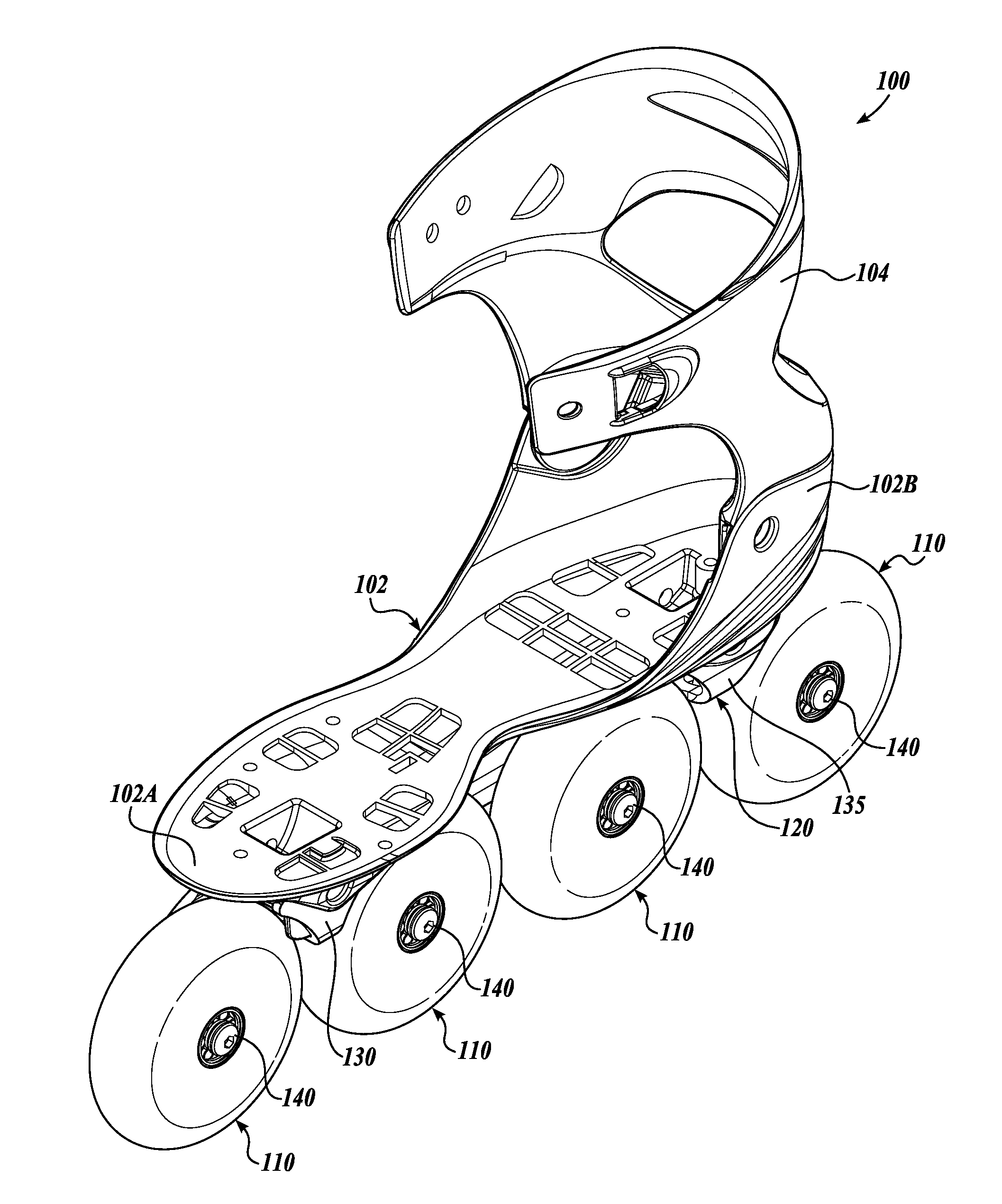
[0025] FIG. 1 is a perspective view of an embodiment of a low-vibration inline skate in accordance with the present invention;
[0026] FIG. 2A is a right side view of the inline skate shown in FIG. 1;
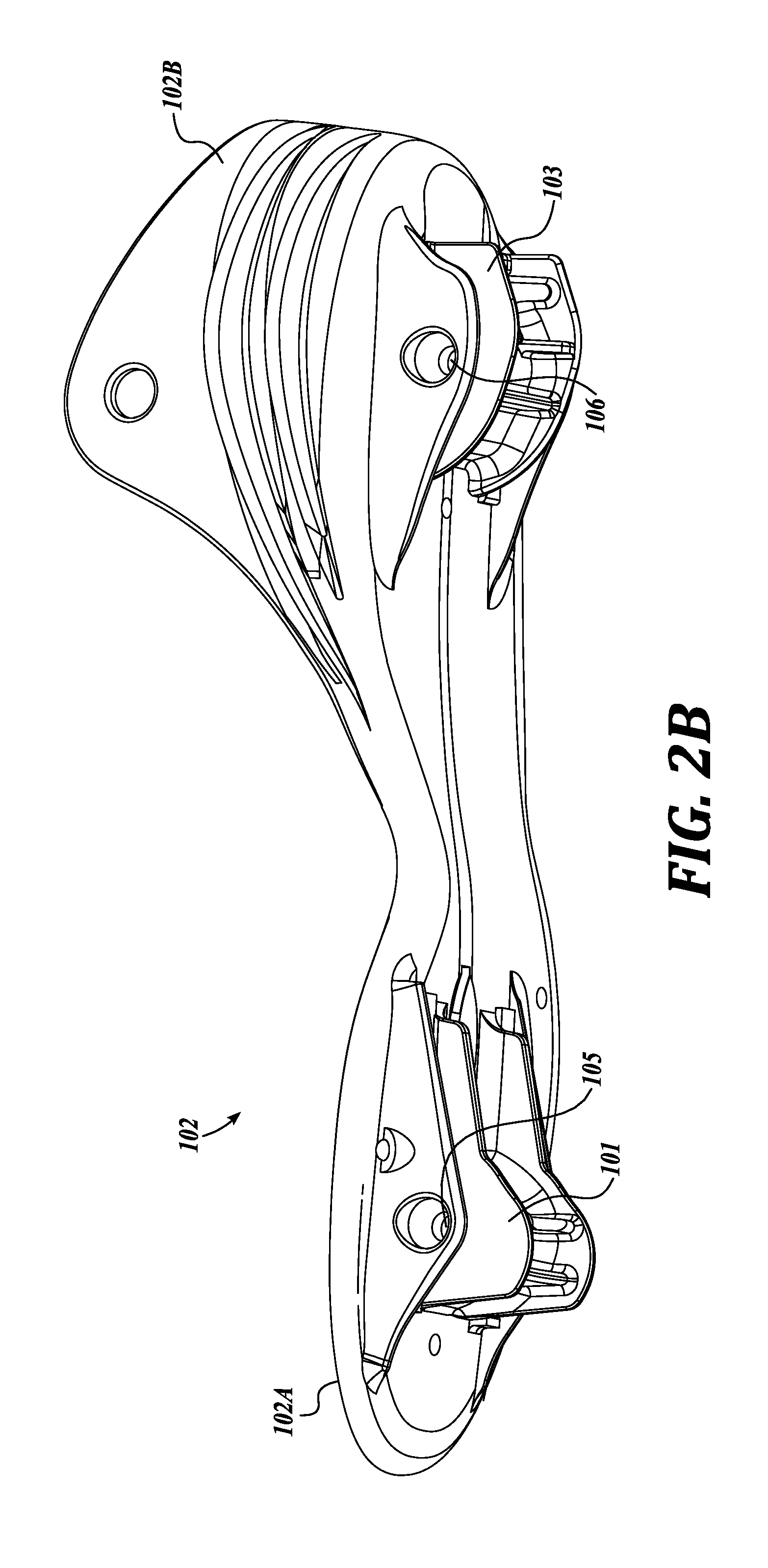
[0027] FIG. 2B is a perspective lower side view of the base of the inline skate shown in FIG. 1, illustrating the forward and rearward bosses for attachment to the frame;
[0028] FIG. 3A is a perspective view of the frame for the inline skate shown in FIG. 1;
[0029] FIG. 3B is a plan view of the frame for the inline skate shown in FIG. 1;
[0030] FIG. 4 is a rear exploded view showing the frame and the base for the inline skate shown in FIG. 1;
[0031] FIG. 5 is an exploded view of the front wheel and axle assembly for the inline skate shown in FIG. 1;
[0032] FIG. 6 is an exploded view showing another embodiment of the axle assembly for the inline skate shown in FIG. 1; and
[0033] FIG. 7 shows is an exploded view showing another embodiment of the axle assembly for the inline skate shown in FIG. 1.
DETAILED DESCRIPTION
[0034] Referring now to the FIGURES which illustrate a currently preferred embodiment of a single-wall inline skate 100 in accordance with the present invention with the foot enclosure portions not shown, wherein like identifiers indicate like parts. FIG. 1 is a front-right perspective view of the inline skate 100, FIG. 2A is a right side view of the single-wall inline skate 100, and FIG. 2B is a lower side view of the base 102 of the skate 100. The boot or foot-enclosing portion and conventional lacing, straps and the like are not shown to better illustrate novel aspects of the single-wall inline skate 100. In the currently preferred embodiment, the inline skate 100 shown in FIG. 1 is intended for the left foot of the user. The right-foot skate has a similar arrangement but in mirror symmetry.
[0035] The skate 100 includes four wheel assemblies 110 rotatably mounted to a frame 120 having a single sidewall 122. In other embodiments the skate may include a different number of in-line wheel assemblies 110, for example two, three, five, or six wheel assemblies. Unlike conventional inline skates, the outer or lateral side of the wheel assemblies 110 are not obscured by a frame sidewall or other frame structure.
[0036] A contoured skate base 102 is attached to the frame 120. The base 102 is configured to underlie and support the skater's foot. The base 102 includes a forward foot portion 102A that is integral with a rearward heel cup portion 102B. An ankle collar 104 is pivotably attached to the heel cup portion 102B.
[0037] As seen most clearly in FIG. 2B, which shows the base 102 in isolation, a first attachment boss 101 extends downwardly from the forward portion 102A of the base 102 and a second attachment boss 103 extends downwardly from the heel portion 102B of the base 102. The first and second attachment bosses 101, 103 are configured to be attached to the frame 120 with fasteners 105A, 106A (FIG. 2A) that extend through boss apertures 105, 106 and corresponding apertures 121, 121' in the frame 120. Other attachment methods are contemplated, and may be used to attach the frame to the base of the skate boot.
[0038] The wheel assemblies 110 include an elastic ground-engaging portion 111 for example an abrasion-resistant, high-density urethane annular wheel. The ground-engaging wheel 111 is fixedly attached to a hub 113 having a central through aperture. A bearing assembly 112 is installed in the central aperture. The bearing assemblies 112 in a current embodiment includes a pair of coaxial and spaced-apart bearing subassemblies positioned in the wheel 112 central aperture with a spacer therebetween. Each of the wheel assemblies 110 is rotatably mounted on a corresponding one of axle assemblies 140. The axle assemblies 140 are attached to the frame sidewall 122 in a cantilevered arrangement, such that the wheel assemblies 110 are approximately centered below the base 102.
[0039] A perspective view of the frame 120 is shown in isolation in FIG. 3A, and a plan view of the frame 120 is shown in FIG. 3B. Refer also to FIG. 4, which shows an exploded back view of the base 102 and the frame 120. The frame sidewall 122 includes a lower section defining a wheel mounting portion 124 having a plurality of apertures 123 for mounting the axle assemblies 140. The sidewall 122 is preferably located medially, i.e., on the right (or interior) side for the left-foot skate shown in FIG. 1, and on the left (or interior) side for the right-foot skate (not shown). A plurality of locking protrusion 125, each associated with one of the apertures 123, are also visible in FIGS. 3A and 3B.
[0040] The sidewall 122 further includes a forward attachment portion 126 extending upwardly from a front section of the wheel mounting portion 124 and a rearward attachment portion 128 extending upwardly from a back section of the wheel mounting portion 124. Each attachment portion 126 and 128 includes an attachment aperture 121. A generally L-shaped forward attachment member 130 extends from the front section of the sidewall 122. The forward attachment member 130 includes a leg 131 fixed to, or integral with, and extending away from the sidewall 122 and an attachment plate 132 extending upwardly from the leg 131. The attachment plate 132 is generally parallel to the forward attachment portion 126 of the sidewall 122. Similarly, an L-shaped rearward attachment member 135 extends from a back section of the sidewall 122. The rearward attachment member 135 includes a leg 136 fixed to, or integral with, the sidewall 122 and an attachment plate 137 extending upwardly from the leg 136. The attachment plate 137 is generally parallel to the rearward attachment portion 128 of the sidewall 122. The attachment plates 132, 137 include an aperture 121' aligned with a corresponding attachment aperture 121 in the sidewall 122.
[0041] The leg 131 of the forward attachment member 130 and the leg 136 of the rearward attachment member 135 are hourglass shaped, i.e., wide at each end and narrow in the middle, as seen most clearly in FIG. 3B. In particular, the legs 131, 136 are sized and shaped to extend between neighboring wheel assemblies 110, for example at an elevation above the axle assemblies 140. For example, in this embodiment the forward attachment member 130 extends between the two front wheel assemblies 110 and the rearward attachment member 135 extends between the two rear wheel assemblies 110 (see FIG. 2A).
[0042] Referring again to FIGS. 2B and 4, the first and second attachment bosses 101, 103 each include a transverse aperture 105, 106 respectively, that is sized and positioned to slidably receive conventional attachment hardware (not shown), for attaching the base 102 to the frame 120. The first attachment boss 101 of the base 102 slidably engages the frame 120 between the forward attachment portion 126 of the sidewall 122 and the corresponding plate 132 of the forward attachment member 130. Attachment members 105A, 106A (FIG. 2A) extend through corresponding apertures 121, 121', and boss apertures 105 or 106 to attach the base 102 to the frame 120. The second attachment boss 103 of the base 102 slidably engages the frame 120 between the rearward attachment portion 128 of the sidewall 122 and the plate 137 of the rearward attachment member 135. It will be appreciated that the first and second bosses 101, 103 extending down from the foot pad portion of the base 102 provide a leverage arm that improve the user's ability to control the skate frame 120.
[0043] In an alternative embodiment (not shown) a transverse attachment plate extends between a top end of the attachment portions 126, 128 and the corresponding attachment plate 132, 137, and the skate base is attached to the frame with attachment members that extend vertically through mounting apertures in the transverse attachment plate.
[0044] FIG. 5 shows a front end of the frame 120 and wheel assemblies 110, with one of the axle assemblies 140 in exploded view. The axle assemblies 140 include a main axle member 141 having an axle shaft 145 configured to slidably engage the corresponding bearing assembly 112. An outer end 146 of the axle shaft 145 is threaded, and configured to engage an attachment bolt 149. An inner end of the axle shaft 145 defines a flange 143, and an end portion 142 extends through the corresponding aperture 123 in the wheel mounting portion 122 of the frame 120. The end portion 142 includes a threaded aperture 147, and the main axle member 141 is fixed to the frame 120 with an attachment member 148 that engages the threaded aperture 147. In this embodiment the attachment member 148 is configured to permanently fix the axle member 141 to the wheel mounting portion 122. In other embodiments the attachment member 148 is removable, such that the axle member 141 may be removed. The end portion 142 is sized such that the flange 143 and the attachment member 148 clampingly engage the frame 120. The flange 143 includes a shaped portion 144, for example a flat face portion that is sized and shaped to engage a corresponding one of the locking protrusions 125 on the wheel mounting portion 122 of the frame 120, such that the main axle member 141 is prevented from rotating with respect to the frame 120.
[0045] The attachment member 148 in this embodiment fixes the axle member 141 to the sidewall 122. In alternative embodiments the axle members are permanently fixed to the sidewall 122. For example, the attachment member 148 may be configured with a drive head that only allows the attachment member 148 to be rotated in the direction that tightens the attachment. Alternatively the axle member may be co-formed with the sidewall 122, or formed as a single piece that is permanently affixed to the sidewall 122 by welding, brazing, adhesives, or the like.
[0046] It will be appreciated by persons of skill in the art that with this arrangement the main axle member 141 is advantageously not pre-tensioned by the attachment members 148 and 149. In addition, removing and replacing the wheel assemblies 110 is simplified because the main axle member 141 is prevented from rotating when removing and replacing the attachment member 149.
[0047] An alternative embodiment of an axle assembly 240 is shown in FIG. 6. The axle assembly 240 is similar to the axle assembly 140 described above, but provides protection against unintentional loosening of the attachment member 149 during use. In this embodiment the main axle member 241 has an axle shaft 245 that includes one or more shaped end recesses or notches 244 (two shown). An annular cap member 250 is disposed between attachment member 149 and the main axle member 141 and corresponding bearing assembly 112. The cap member 250 includes a central aperture 252 configured to receive the threaded end of attachment member 149 therethrough. The annular cap member 250 includes corresponding protrusions 254 that are configured to engage the end notches 244 on the axle shaft 245. The shaped flange 143 engages the flange protrusion 125 preventing the axle member 141 from rotating, and the engagement of the protrusions 254 with the end notches 244 similarly prevents the cap member 250 from rotating. The annular cap member 250 isolates the attachment member 149 from the rotational motion of the bearing assembly 112. The annular cap member 250 therefore protects the attachment member 149 from coming loose due to the rotations of the wheel assembly 110, improving safety to the skater.
[0048] Another alternative embodiment of an axle assembly 240 is shown in FIG. 7. In this embodiment the axle member 341 includes an axle shaft 345 having a reduced-diameter distal end 344. A cap member 350 is configured to slidably engage the distal end 344 in a manner that rotationally locks the cap 350 to the axle shaft 345, i.e., such that the cap member 350 will not rotate with respect to the axle member 341. In this embodiment the distal end 344 includes one or more outwardly-extending ribs 347, and the cap member 350 includes a tubular portion 354 having one or more channels 357, and a flange 352. The tubular portion 354 is configured to slide onto the distal end 344 such that the ribs 347 slidably engage corresponding channels 357 such that the cap member 350 is rotationally locked with the axle member 341. Alternative locking mechanisms are contemplated. For example the tubular portion 354 and distal end 344 may be non-circular, e.g., oval or polygonal. In another example the tubular portion 354 may include a shaped distal end, for example a plurality of teeth or longitudinal extensions, that are configured to engage corresponding recesses in the axle member 341. The cap member in these various embodiments are configured to prevent the rotation of the wheel assembly, for example the bearing assembly 112 from frictionally transmitting rotational forces to the attachment bolt 149, to prevent the attachment bolt 149 from coming loose from the axle member.
[0049] While illustrative embodiments have been illustrated and described, it will be appreciated that various changes can be made therein without departing from the spirit and scope of the invention.
* * * * *
D00000
D00001
D00002
D00003
D00004
D00005
D00006
D00007
D00008
XML
uspto.report is an independent third-party trademark research tool that is not affiliated, endorsed, or sponsored by the United States Patent and Trademark Office (USPTO) or any other governmental organization. The information provided by uspto.report is based on publicly available data at the time of writing and is intended for informational purposes only.
While we strive to provide accurate and up-to-date information, we do not guarantee the accuracy, completeness, reliability, or suitability of the information displayed on this site. The use of this site is at your own risk. Any reliance you place on such information is therefore strictly at your own risk.
All official trademark data, including owner information, should be verified by visiting the official USPTO website at www.uspto.gov. This site is not intended to replace professional legal advice and should not be used as a substitute for consulting with a legal professional who is knowledgeable about trademark law.