Endovascular Devices And Methods
KUGLER; CHAD J. ; et al.
U.S. patent application number 16/396171 was filed with the patent office on 2019-08-15 for endovascular devices and methods. This patent application is currently assigned to BRIDGEPOINT MEDICAL, INC.. The applicant listed for this patent is BRIDGEPOINT MEDICAL, INC.. Invention is credited to ROBERT E. ATKINSON, CHAD J. KUGLER.
| Application Number | 20190247628 16/396171 |
| Document ID | / |
| Family ID | 37986239 |
| Filed Date | 2019-08-15 |


| United States Patent Application | 20190247628 |
| Kind Code | A1 |
| KUGLER; CHAD J. ; et al. | August 15, 2019 |
ENDOVASCULAR DEVICES AND METHODS
Abstract
Devices and methods for the treatment of chronic total occlusions are provided. One disclosed embodiment comprises a method of facilitating treatment via a vascular wall defining a vascular lumen containing an occlusion therein. The method includes providing an intravascular device having a distal portion with a lumen extending therein; inserting the device into the vascular lumen; positioning the distal portion in the vascular wall; and directing the distal portion within the vascular wall.
| Inventors: | KUGLER; CHAD J.; (BUFFALO, MN) ; ATKINSON; ROBERT E.; (LAKE ELMO, MN) | ||||||||||
| Applicant: |
|
||||||||||
|---|---|---|---|---|---|---|---|---|---|---|---|
| Assignee: | BRIDGEPOINT MEDICAL, INC. PLYMOUTH MN |
||||||||||
| Family ID: | 37986239 | ||||||||||
| Appl. No.: | 16/396171 | ||||||||||
| Filed: | April 26, 2019 |
Related U.S. Patent Documents
| Application Number | Filing Date | Patent Number | ||
|---|---|---|---|---|
| 13037797 | Mar 1, 2011 | 10315010 | ||
| 16396171 | ||||
| 11518521 | Sep 11, 2006 | 7918870 | ||
| 13037797 | ||||
| 60716287 | Sep 12, 2005 | |||
| Current U.S. Class: | 1/1 |
| Current CPC Class: | A61B 2017/22095 20130101; A61M 25/09 20130101; A61M 2025/09175 20130101; A61M 2025/09191 20130101; A61M 2025/09083 20130101; A61M 25/104 20130101; A61M 2025/09133 20130101 |
| International Class: | A61M 25/09 20060101 A61M025/09 |
Claims
1. A method of treating an occlusion of a blood vessel, comprising: advancing an intravascular device within a lumen of the blood vessel to a position proximate the occlusion, wherein the intravascular device comprises: an elongate shaft defining a central longitudinal axis; an inflatable balloon including an expandable portion; a first lumen; and a second lumen extending coaxially with the central longitudinal axis to a distal opening positioned distal of the expandable portion of the inflatable balloon; inflating the inflatable balloon to expand the expandable portion and orient a distal opening of the first lumen toward an intimal layer of a wall of the blood vessel; advancing a subintimal device through the first lumen upon expansion of the expandable portion and through the intimal layer of the wall of the blood vessel.
2. The method of claim 1, further comprising: advancing the subintimal device distally within a subintimal space of the blood vessel.
3. The method of claim 2, wherein the subintimal space is disposed outside of the intimal layer of the wall of the blood vessel and inside of a medial layer of the wall of the blood vessel.
4. The method of claim 1, further comprising: advancing the subintimal device concentrically around the occlusion of the blood vessel.
5. The method of claim 1, wherein the distal opening of the second lumen is centered on the central longitudinal axis.
6. The method of claim 1, wherein advancing the intravascular device within the lumen of the blood vessel further comprises advancing the intravascular device over a guidewire disposed within the second lumen.
7. The method of claim 1, wherein the intravascular device includes a tubular distal tip defining the distal opening of the second lumen, the tubular distal tip being disposed distal of a distal end of the expandable portion.
8. The method of claim 1, wherein the inflatable balloon has a substantially symmetrical outer profile.
9. The method of claim 1, wherein the first lumen extends helically around the inflatable balloon.
10. A method of treating an occlusion of a blood vessel, comprising: advancing an intravascular device within a lumen of the blood vessel to a position proximate the occlusion, wherein the intravascular device comprises: an elongate shaft defining a central longitudinal axis; an inflatable balloon including an expandable portion; a first lumen extending along an exterior surface of the expandable portion of the inflatable balloon; and a second lumen extending coaxially with the central longitudinal axis to a distal opening positioned distal of the expandable portion of the inflatable balloon; inflating the inflatable balloon to expand the expandable portion and orient a distal opening of the first lumen toward an intimal layer of a wall of the blood vessel; advancing a subintimal device through the first lumen upon expansion of the expandable portion and through the intimal layer of the wall of the blood vessel.
11. The method of claim 10, wherein the distal opening of the second lumen is located distally of the distal opening of the first lumen.
12. The method of claim 10, wherein the second lumen is a guidewire lumen and the distal opening of the second lumen faces distally.
13. The method of claim 12, wherein advancing the intravascular device within the lumen of the blood vessel further comprises advancing the intravascular device over a guidewire disposed within the guidewire lumen.
14. The method of claim 10, wherein the first lumen is disposed externally to the elongate shaft.
15. The method of claim 10, further comprising: advancing the subintimal device distally of the occlusion of the blood vessel.
16. A method of treating an occlusion of a blood vessel, comprising: advancing an intravascular device within a lumen of the blood vessel to a position proximate the occlusion, wherein the intravascular device comprises: an elongate shaft defining a central longitudinal axis; an inflatable balloon including an expandable portion; a first lumen; and a second lumen extending coaxially with the central longitudinal axis to a distal opening positioned distal of a distal end of the expandable portion of the inflatable balloon; wherein a distal opening of the first lumen is positioned intermediate a proximal end of the expandable portion and the distal end of the expandable portion; inflating the inflatable balloon to expand the expandable portion and orient the distal opening of the first lumen toward an intimal layer of a wall of the blood vessel; advancing a subintimal device through the first lumen upon expansion of the expandable portion and through the intimal layer of the wall of the blood vessel.
17. The method of claim 16, wherein an outer profile of the expandable portion includes a tapered proximal section, a tapered distal section, and an intermediate section connecting the tapered proximal section and the tapered distal section.
18. The method of claim 16, wherein the first lumen extends along an exterior surface of the elongate shaft and the inflatable balloon.
19. The method of claim 16, wherein the distal opening of the second lumen is centered on the central longitudinal axis.
20. The method of claim 16, further comprising: advancing the subintimal device distally between the intimal layer and a medial layer of the wall of the blood vessel along the occlusion.
Description
CROSS REFERENCE TO RELATED APPLICATIONS
[0001] This is a continuation application of application Ser. No. 13/037,797, filed Mar. 1, 2011, which is a continuation of application Ser. No. 11/518,521, filed Sep. 11, 2006, now U.S. Pat. No. 7,918,870, which claims the benefit of U.S. Provisional Application No. 60/716,287, filed Sep. 12, 2005, the contents of which are incorporated herein by reference.
FIELD OF THE INVENTION
[0002] The inventions described herein relate to devices and associated methods for the treatment of chronic total occlusions. More particularly, the inventions described herein relate to devices and methods for crossing chronic total occlusions and subsequently performing balloon angioplasty, stenting, atherectomy, or other endovascular methods for opening occluded blood vessels.
BACKGROUND OF THE INVENTION
[0003] Due to age, high cholesterol and other contributing factors, a large percentage of the population has arterial atherosclerosis that totally occludes portions of the patient's vasculature and presents significant risks to patient health. For example, in the case of a total occlusion of a coronary artery, the result may be painful angina, loss of cardiac tissue or patient death. In another example, complete occlusion of the femoral and/or popliteal arteries in the leg may result in limb threatening ischemia and limb amputation.
[0004] Commonly known endovascular devices and techniques are either inefficient (time consuming procedure), have a high risk of perforating a vessel (poor safety) or fail to cross the occlusion (poor efficacy). Physicians currently have difficulty visualizing the native vessel lumen, cannot accurately direct endovascular devices toward visualized lumen, or fail to advance devices through the lesion. Bypass surgery is often the preferred treatment for patients with chronic total occlusions, but less invasive techniques would be preferred.
SUMMARY OF THE INVENTION
[0005] To address this and other unmet needs, the present invention provides, in exemplary non-limiting embodiments, devices and methods for the treatment of chronic total occlusions. The disclosed methods and devices are particularly beneficial in crossing coronary total occlusions but may also be useful in other vessels including peripheral arteries and veins. In exemplary embodiments, total occlusions are crossed using methods and devices intended to provide a physician visualization of the occluded vascular lumen or provide physical protection for the wall of the artery to prevent perforation. In additional embodiments, devices and methods are disclosed that enhance the ability to direct and advance a guide wire within the vessel lumen.
[0006] In one embodiment, visualization of the occluded segment may be achieved by placing a subintimal device in the space around the area of the lesion. Subintimal device placement may be achieved with a subintimal device directing catheter. The catheter orients a subintimal device so that it passes along the natural delamination plane between intima and media approximating a helical path. The subintimal device directing catheter may be an inflatable balloon catheter having proximal and distal ends with two wire lumens. One lumen accepts a conventional guide wire while the second lumen accepts the subintimal device. In an alternative embodiment, the wire directing catheter may be a guide catheter with distal geometry that steers the subintimal device with the appropriate orientation to enter the subintimal space and advance in a helical pattern around the lesion. Visualization of the artery may be achieved as the subintimal device encircles the artery with each helical turn. The wire's shape may approximate the inside diameter of the lumen and also may define axial bends or tortuosity in the vessel. The subintimal device may further serve the purpose of providing mechanical protection for the artery from perforation or damage from subsequently used devices. Once the subintimal device is in place around the lesion, a number of conventional techniques may be used to cross the lesion including for example stiff guide wires, lasers, ultrasonic energy, mechanical dissection, and atherectomy. Alternatively, a guide wire support device may be used that has the ability to rotationally engage the lesion through helical corkscrew profile on the outside surface. An additional aspect may be the ability to independently steer or direct a guide wire support catheter within the vessel lumen while maintaining the ability to rotate, engage, and advance the corkscrew catheter shaft.
[0007] The subintimal device may have a mechanism that rotationally engages the arterial tissues and helps drive the wire through the subintimal space. This mechanism may allow the physician to torque the wire at its proximal end, engage the subintimal tissues and achieve wire advancement. This aspect of the wire may for example include a raised helical corkscrew protrusion on the outside surface of the wire. An additional aspect of the subintimal device may include an atraumatic tip that aids in the prevention of arterial perforation.
BRIEF DESCRIPTION OF THE DRAWINGS
[0008] It is to be understood that both the foregoing summary and the following detailed description are exemplary. Together with the following detailed description, the drawings illustrate exemplary embodiments and serve to explain certain principles. In the drawings,
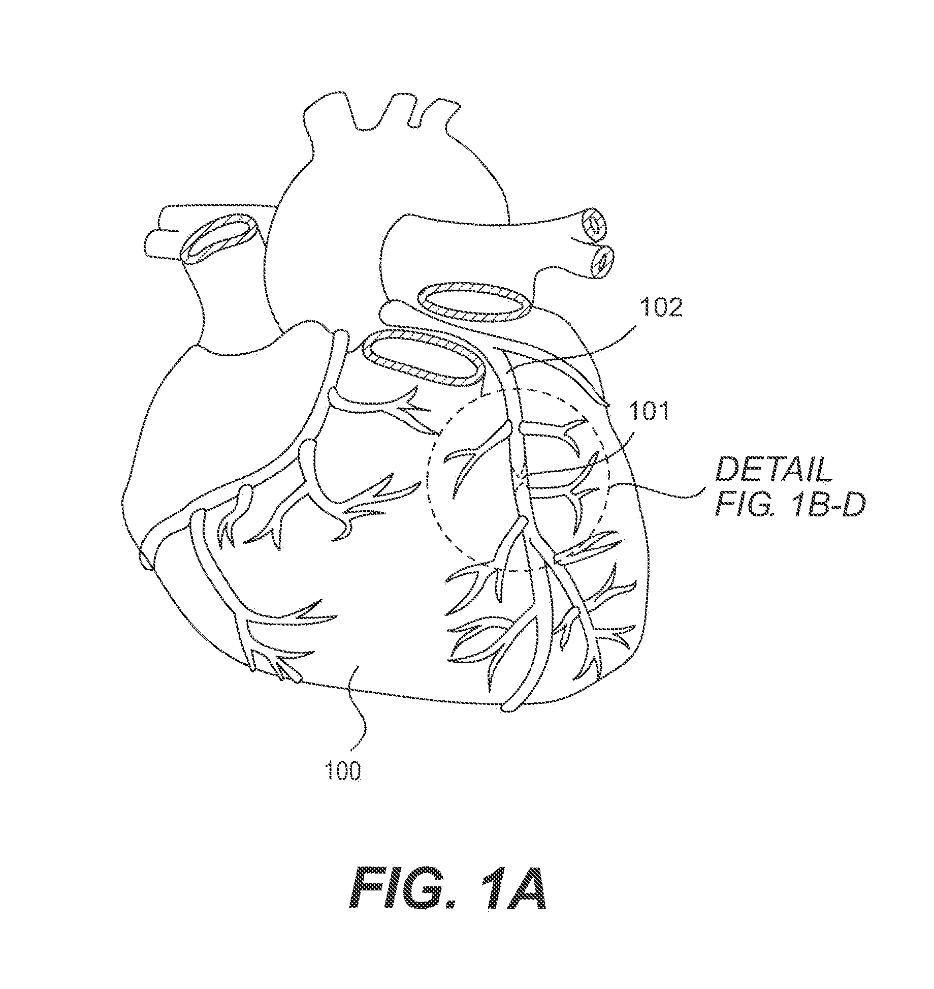
[0009] FIG. 1A shows an illustration of a heart showing a coronary artery that contains a chronic total occlusion and illustrates the position of the detail section shown in FIGS. 1B-D;
[0010] FIG. 1B is an illustration showing a magnified view of a chronic total occlusion;
[0011] FIG. 1C is a representation of fluoroscopy image of the chronic total occlusion;
[0012] FIG. 1D is a representation of a fluoroscopy image with a subintimal device in position around the lesion;
[0013] FIG. 2 is a schematic representation of a coronary artery showing the intimal, medial and adventitial layers;
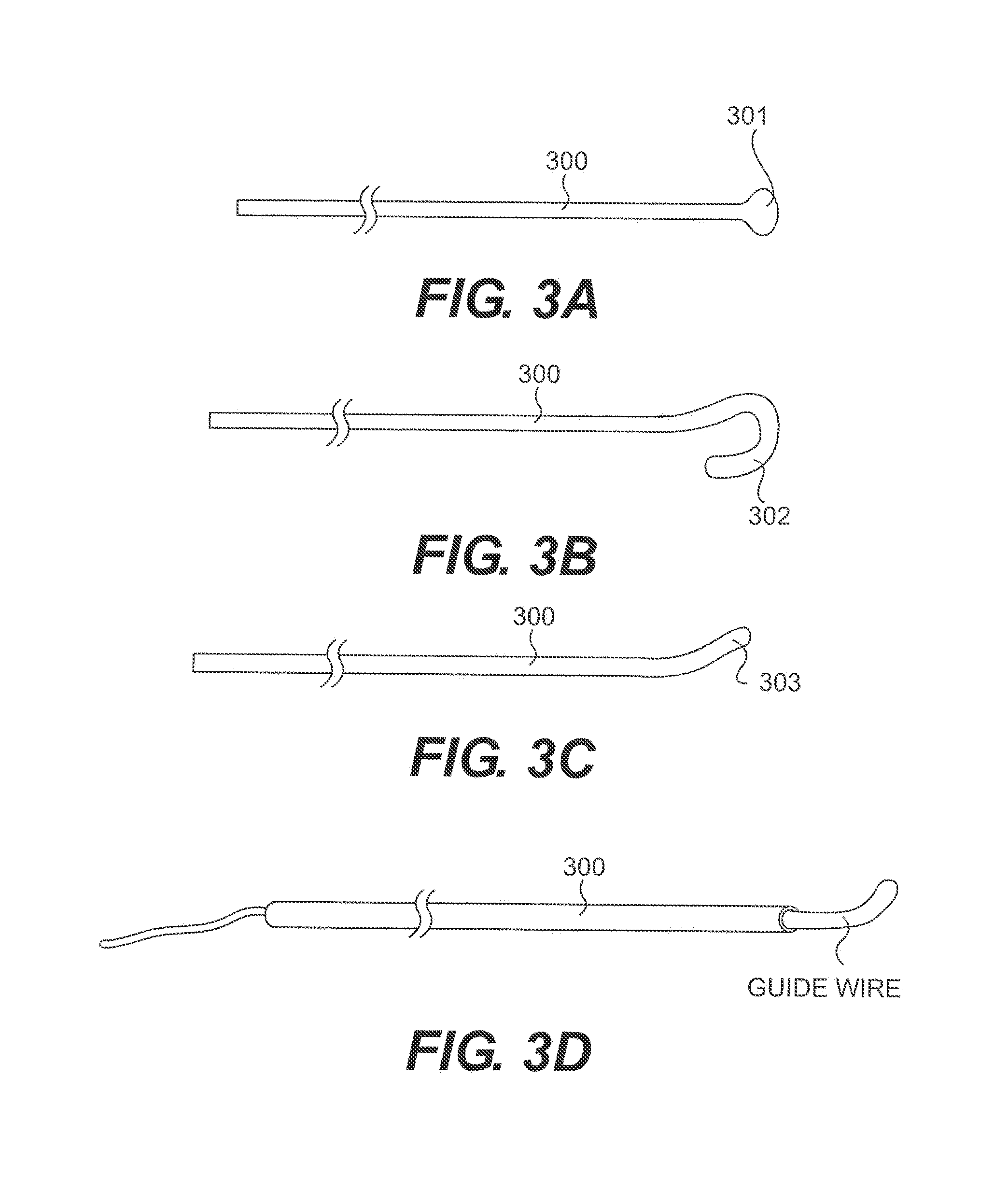
[0014] FIGS. 3 A-D illustrate atraumatic tip configurations of a subintimal device;
[0015] FIG. 4A is a schematic illustration of a subintimal device;
[0016] FIGS. 4B and 4D are cross-sectional views of the subintimal device shown in FIG. 4A taken along line A-A;
[0017] FIG. 4C shows a subintimal device body embodiment describing a multi layered coil construction;
[0018] FIGS. 4 E-G show alternative subintimal device body embodiments;
[0019] FIGS. 5A-D show embodiments of subintimal devices having various surface features;
[0020] FIGS. 6A-C show schematic and sectional views of a subintimal device directing balloon catheter;
[0021] FIG. 7 is a sectional view of a totally occluded vessel with a subintimal device directing balloon catheter inflated proximal to the lesion and a subintimal device advanced partially around the lesion; and
[0022] FIGS. 8A-C show an embodiment of an advancement device used to advance devices across the lesion within the vessel lumen.
DETAILED DESCRIPTION OF EXEMPLARY EMBODIMENTS
[0023] The following detailed description should be read with reference to the drawings in which similar elements in different drawings are numbered the same. The drawings, which are not necessarily to scale, depict illustrative embodiments and are not intended to limit the scope of the invention.
[0024] Referring to FIG. 1, a diseased heart 100 including a chronic total occlusion 101 of a coronary artery 102. FIG. 1B shows a magnified view of a chronic total occlusion 101 within coronary artery 102. The figure shows arterial sections both proximal 103 and distal 104 of lesion 101. The proximal segment 103 may be easily accessed using endovascular devices and has adequate blood flow to supply the cardiac muscle. The distal segment 104 is not easily accessed with interventional devices and has significantly reduced blood flow as compared to proximal segment 103. A commonly performed diagnostic procedure called an angiogram infuses a radiopaque fluid into the arterial bloodstream through a percutaneously placed angiography catheter and records two dimensional images of the arterial pathways using a fluoroscope. FIG. 1C shows an example of an angiographic image of a chronic total occlusion. It is common that the angiogram allows a physician to visualize the proximal segment 103 but does not allow visualization of the distal segment.
[0025] An aspect of the disclosure enhances arterial visualization by placing a radiopaque device within the subintimal space around the chronic total occlusion. For the purpose of description, not limitation, the term "subintimal device" will henceforth refer to the wire placed within the subintimal space for purposes of visualization, protecting the vessel, or other purpose, while the term "guide wire" will refer to the wire placed within the vascular lumen for purposes of advancing diagnostic and therapeutic devices within the lumen. FIG. 1D is an additional angiographic image example showing proximal arterial segment 103 and subintimal device 105 positioned concentrically around the chronic total occlusion and within the subintimal space. The subintimal device 105 defines the approximate inside diameter of the artery and also defines axial bends or tortuosity in the vessel.
[0026] FIG. 2 shows coronary artery 102 with intimal layer 200 (for sake of clarity, the multi layer intima is shown as a single homogenous layer). Concentrically outward of the intima is the medial layer 201 (which also is comprised of more than one layer but is shown as a single layer). The transition between the external most portion of the intima and the internal most portion of the media is referred to as the subintimal space. The outermost layer of the artery is the adventitia 202.
[0027] One aspect of the disclosure is the design of the subintimal device. Embodiments of the subintimal device distal tip are described in FIGS. 3A-D where the tip includes an atraumatic element. Examples of atraumatic elements are a ball tip 301, looped tip 302 and directional tip 303. These elements are intended to distribute axial forces over larger areas of tissue and may reduce the chance of vessel perforation. An additional aspect of the directional tip 303 is ability to torsionally direct the tip and control the path of the device through the subintimal space. The ball tip 301 may be formed from a suitable metallic material including but not limited to stainless steel, silver solder, or braze. The ball tip 301 may also be formed from suitable polymeric materials or adhesives including but not limited to polycarbonate, polyethylene or epoxy. The loop tip 302 and directional tip 303 may be created during the manufacturing process (for example by heat setting or mechanical deformation) or the tip may be shaped (for example by mechanical deformation) by the physician.
[0028] In an alternative embodiment, FIG. 3D describes a subintimal device where the hollow internal diameter of the body 300 defines a guide wire lumen. The lumen has proximal and distal ends and can accept a guide wire. The guide wire provides an atraumatic element at its distal end and also provides a mechanism for rotationally steering the subintimal device through the subintimal space. The guide wire may be pushed forward by the subintimal device through an element (i.e. bearing surface) at the proximal or distal end of the subintimal device. This element may provide interference in the axial direction while allowing for relative rotation between the subintimal device and guide wire. An example of a bearing surface may be a collar crimped to the distal end of the guide wire with an outside diameter larger in dimension than the guide wire lumen within the subintimal device.
[0029] An additional aspect of the subintimal device is the construction of the device body. The flexibility and torquability of the device body can affect the physician's ability to achieve a helical and subintimal path around the lesion. The sectional view shown in FIG. 4B describes a device body made of a multitude of independent coils 401-403 concentrically wound in opposing directions. These coils can diametrically interact (for example internal coil diametrically expands while the external coil diametrically contracts) with an applied torque. This interaction can provide torsional strength while maintaining axial flexibility. The device body may have sections of increased or decreased torsional or axial rigidity. For example, the proximal most portion of the subintimal device may be formed from a solid stainless steel tube and the distal most section may have the aforementioned multiple coil construction. Alternatively, the device core 404 may be hollow or may contain a permanently fixed wire within its internal lumen. A permanently fixed wire may provide an increase in axial or torsional stiffness. A permanently fixed wire may also have a tapering cross section to increase the distal flexibility. The lumen within a hollow subintimal device may also be used for the insertion of a guide wire. Coils 401-403 and core wire 404 may be made of a suitable metallic or polymeric materials including but not limited to stainless steel, nickel titanium, platinum or ultra high molecular weight polyethylene.
[0030] In an alternative embodiment, a subintimal device body construction is shown in FIG. 4D where a single coil may be positioned over an internal core. The additional embodiment shown in FIG. 4E shows a single open wound coil 405 as the subintimal device body.
[0031] In another embodiment, the subintimal device body may be constructed in part or in total of a single layer coil with geometric features along the coil length that allow adjacent coils to engage (for example mechanical engagement similar to the teeth of a gear). FIG. 4F shows coil 406 closely wound such that the multitude of teeth 407 along the coil edges are in contact such that the peaks of one coil falls within the valleys of the adjacent coil. A conventional coil reacts to an applied torsional load by diametrically expanding or contracting, thus forcing the wire surfaces within a turn of the coil to translate with respect to its neighboring turn. The construction of coil 406 resists the translation of wire surfaces within the coil thus resisting the diametric expansion or contraction (coil deformation). An increased resistance to coil deformation increases the torsional resistance of the device body while the coiled construction provides axial flexibility. An exemplary construction may include a metallic tube where the coil pattern 406 and teeth 407 are cut from the tube diameter using a laser beam. FIG. 4G shows subintimal device body 300 that is for example continuous metallic tube with distal laser cut coil segment 406 and proximal solid tube 408. Tube materials include but are not limited to stainless steel and nickel titanium. Alternatively, the coil 406 may be wound from a continuous wire. The wire has a cross section that for example has been mechanically deformed (stamped) to form the teeth and allow coil engagement.
[0032] Another aspect of the disclosure is the exterior surface of the subintimal device. FIG. 5A shows an embodiment where the device body 300 has an external corkscrew 500 that has the ability to rotationally engage the arterial tissues and help drive the device through the subintimal space. FIG. 5B describes an embodiment where one or more round corkscrew members 501 are concentrically wound on the outside of the body 300. Alternatively FIG. 5C describes a multi-layer device body with layers 401-403 where corkscrew member 503 h element of larger cross sectional area wound within the external concentric coil 403. Alternative corkscrew embodiments may include triangular, square, or her cross sections that may aid in tissue engagement and subintimal device advancement. In another exemplary embodiment shown in FIG. 5D, a polymer tube with corkscrew profile 502 may be concentrically positioned around device body 300. Withdrawal of a subintimal device that rotationally engages the arterial tissues may be completed by rotating the device in the opposite direction thus driving the device back out of the subintimal space.
[0033] An additional aspect of the disclosure may be a device that directs the subintimal device through the intima and into the subintimal space. In one embodiment shown in FIGS. 6A-C, a balloon catheter with distal balloon 600 and proximal balloon inflation lumen 601 may be advanced over a guide wire that traverses guide wire lumen 602. Once in position us proximal of the chronic total occlusion, the balloon may be inflated within the vessel lumen to direct the subintimal device lumen 603 toward the vessel wall at orientation for subintimal device penetration into the intima and through the subintimal space. FIG. 7 shows subintimal balloon catheter 700 positioned and inflated within coronary artery 102. Subintimal device 105 has been advanced through subintimal device lumen 603 and positioned concentrically outside the chronic total occlusion 101, outside the intimal layer 200, and inside the medial layer 201 and may be contained in the subintimal space.
[0034] An alternative method for achieving subintimal position may use a guide catheter that has distal geometry that directs the device toward the interior vessel wall with the appropriate orientation. An example may be a guide catheter that has a permanently formed curve at the distal end suitable for device advancement. Alternatively, the catheter may be actively steerable so that the physician can choose an orientation insitu.
[0035] An additional aspect of the disclosure is the method and devices used to advance devices across the lesion within the vessel lumen. A number of conventional techniques may be used including stiff guide wires, lasers, ultrasonic energy, mechanical dissection, atherectomy and other techniques known to those skilled in the art. One aspect of the disclosure may be a guide wire support device intended to enhance guide wire stiffness, engage the lesion thus providing axial support, and allow the physician to direct the tip of the guide wire. FIGS. 8A-8C describe a wire support device where external shaft 800 may be comprised of one or more coils intended to provide axial flexibility and torsional rigidity. External helical profile 801 exists on the outside of the external shaft 800 and may provide mechanical engagement with the lesion. FIG. 8B shows a partial sectional view of the wire support device where internal shaft 803 resides concentrically within the external shaft. The internal shaft 803 contains a guide wire lumen capable of accepting conventional guide wires. The internal shaft may also be comprised of one or more coils. FIG. 8C shows a partial enlarged view of the internal shaft 803 where a gap 804 between adjacent coils allow articulation of the shaft upon proximal withdrawal of actuation wire 805. External shaft 800 can freely rotate with respect to internal shaft 803 when the shaft is in the straight and actuated positions.
[0036] From the foregoing, it will be apparent to those skilled in the art that the present invention provides, in exemplary non-limiting embodiments, devices and methods for the treatment of chronic total occlusions. Further, those skilled in the art will recognize that the present invention may be manifested in a variety of forms other than the specific embodiments described and contemplated herein. Accordingly, departures in form and detail may be made without departing from the scope and spirit of the present invention as described in the appended claims.
* * * * *
D00000
D00001
D00002
D00003
D00004
D00005
D00006
D00007
D00008
D00009
D00010
XML
uspto.report is an independent third-party trademark research tool that is not affiliated, endorsed, or sponsored by the United States Patent and Trademark Office (USPTO) or any other governmental organization. The information provided by uspto.report is based on publicly available data at the time of writing and is intended for informational purposes only.
While we strive to provide accurate and up-to-date information, we do not guarantee the accuracy, completeness, reliability, or suitability of the information displayed on this site. The use of this site is at your own risk. Any reliance you place on such information is therefore strictly at your own risk.
All official trademark data, including owner information, should be verified by visiting the official USPTO website at www.uspto.gov. This site is not intended to replace professional legal advice and should not be used as a substitute for consulting with a legal professional who is knowledgeable about trademark law.