Dishwasher
KIM; Ilhwan ; et al.
U.S. patent application number 16/273666 was filed with the patent office on 2019-08-15 for dishwasher. The applicant listed for this patent is LG Electronics Inc.. Invention is credited to Ilhwan KIM, Seunghun KIM, Sangwoo WOO.
| Application Number | 20190246868 16/273666 |
| Document ID | / |
| Family ID | 65411786 |
| Filed Date | 2019-08-15 |


View All Diagrams
| United States Patent Application | 20190246868 |
| Kind Code | A1 |
| KIM; Ilhwan ; et al. | August 15, 2019 |
DISHWASHER
Abstract
A dishwasher includes a case, a sump connected to an inside of the case and collecting washing water, a washing pump receiving washing water from the sump and generating steam, and a steam nozzle connected to the washing pump and spraying steam to the inside of the case. The steam nozzle includes a steam nozzle body having a steam inlet and including a steam accommodating portion accommodating steam therein, a first steam sprayer provided in the steam nozzle body and spraying steam to the inside of the case, and a second steam sprayer provided in the steam nozzle body and disposed at a position farther from the steam inlet than the first steam sprayer, wherein a tunnel flow path penetrating through a lower end of the first steam sprayer is formed to allow steam passing through the tunnel flow path to be introduced into the second steam sprayer.
| Inventors: | KIM; Ilhwan; (Seoul, KR) ; KIM; Seunghun; (Seoul, KR) ; WOO; Sangwoo; (Seoul, KR) | ||||||||||
| Applicant: |
|
||||||||||
|---|---|---|---|---|---|---|---|---|---|---|---|
| Family ID: | 65411786 | ||||||||||
| Appl. No.: | 16/273666 | ||||||||||
| Filed: | February 12, 2019 |
| Current U.S. Class: | 1/1 |
| Current CPC Class: | A47L 15/23 20130101; A47L 15/0036 20130101; A47L 15/4214 20130101; A47L 15/4278 20130101; A47L 15/4225 20130101; A47L 15/4234 20130101; A47L 15/428 20130101; A47L 15/0015 20130101 |
| International Class: | A47L 15/42 20060101 A47L015/42; A47L 15/00 20060101 A47L015/00; A47L 15/23 20060101 A47L015/23 |
Foreign Application Data
| Date | Code | Application Number |
|---|---|---|
| Feb 12, 2018 | KR | 10-2018-0017205 |
Claims
1. A dishwasher comprising: a case that defines an appearance of the dishwasher; a tub that is disposed inside the case and that defines a washing chamber configured to accommodate one or more objects to be cleaned; a sump disposed vertically below the tub and configured to receive washing water; a washing pump configured to receive washing water from the sump and to generate steam from washing water received from the sump; and a steam nozzle connected to the washing pump by a steam hose and configured to spray steam to the washing chamber, wherein the steam nozzle comprises: a steam nozzle body that defines a steam inlet configured to receive steam from the steam hose and a steam accommodating portion configured to accommodate steam, a first steam sprayer disposed in the steam nozzle body and configured to spray steam accommodated in the steam accommodating portion to the washing chamber, and a second steam sprayer disposed in the steam nozzle body at a position farther from the steam inlet than the first steam sprayer, and wherein the first steam sprayer defines a tunnel flow path that penetrates a lower end of the first steam sprayer and that is configured to allow steam to pass through the lower end of the first steam sprayer and be introduced into the second steam sprayer.
2. The dishwasher of claim 1, wherein the first steam sprayer comprises a first steam spray orifice having a first end that is in communication with the tunnel flow path and a second end that is in communication with the washing chamber, and wherein the first steam sprayer is configured to spray a portion of steam introduced to the tunnel flow path to the washing chamber through the first steam spray orifice.
3. The dishwasher of claim 2, wherein a sectional area of the tunnel flow path is greater than a sectional area of the first steam spray orifice.
4. The dishwasher of claim 2, wherein the tunnel flow path has a first end portion facing the steam inlet and a second end portion facing the second steam sprayer, and wherein a sectional area of the first end portion of the tunnel flow path is greater than a sectional area of the second end portion of the tunnel flow path.
5. The dishwasher of claim 2, wherein the steam nozzle body defines a flow path that surrounds at least a portion of the first steam sprayer.
6. The dishwasher of claim 2, wherein the steam inlet is defined at a center portion of the steam nozzle body, and wherein the steam nozzle body extends horizontally from the center portion.
7. The dishwasher of claim 6, wherein the first steam sprayer comprises a pair of first steam sprayers disposed on a first side of the steam inlet and a second side of the steam inlet, the center portion of the steam nozzle body being disposed between the first side and the second side of the steam inlet, and wherein the second steam sprayer comprises a pair of second steam sprayers that are disposed on the first side of the steam inlet and the second side of the steam inlet, each of the pair of second steam sprayers being disposed at a position farther from the steam inlet than each of the pair of first steam sprayers.
8. The dishwasher of claim 7, wherein the tunnel flow path extends in a direction that defines a predetermined angle with respect to a virtual line passing centers of the pair of first steam sprayers.
9. The dishwasher of claim 1, wherein the steam nozzle body defines a flow path that extends from the first steam sprayer toward the second steam sprayer, and wherein a width of the flow path decreases from the first steam sprayer toward the second steam sprayer.
10. The dishwasher of claim 1, wherein the steam nozzle body defines: a pair of coupling holes disposed at both sides of the steam inlet, respectively; and a flow path that surrounds each of the pair of coupling holes.
11. The dishwasher of claim 10, wherein the steam nozzle body comprises at least one guide rib that is disposed between the steam inlet and at least one of the pair of coupling holes and that is configured to guide steam from the steam inlet to the first steam sprayer.
12. The dishwasher of claim 1, wherein the steam nozzle further comprises: an upper case that is coupled with the steam nozzle body and that defines the steam accommodating portion with the steam nozzle body, the upper case defining a first upper case hole that receives the first steam sprayer and a second upper case hole that receives the second steam sprayer; and a lower case that seats the steam nozzle body and that is coupled to the upper case to define an internal space configured to accommodate the steam nozzle body.
13. The dishwasher of claim 1, wherein the steam nozzle body further defines at least one drain hole disposed at a surface of the steam nozzle body and configured to drain water from the steam accommodating portion.
14. The dishwasher of claim 1, wherein the tub defines a front opening disposed at a front surface of the tub and configured to receive the one or more objects, wherein the steam nozzle is disposed at a lower portion of the front opening and is configured to spray steam in an upward and rearward direction, and wherein the steam nozzle body extends in a lateral direction across the lower portion of the front opening.
15. The dishwasher of claim 1, wherein the steam nozzle body defines: a pair of coupling recesses that are recessed from a surface of the steam nozzle body toward the steam accommodating portion and that are disposed at both sides of the steam inlet, respectively; and a flow path that surrounds each of the pair of coupling recesses.
16. The dishwasher of claim 1, wherein the steam nozzle body defines: a first flow path that extends from the steam inlet toward the first steam sprayer; and a second flow path that extends from the first steam sprayer toward the second steam sprayer, and wherein the tunnel flow path connects the first flow path to the second flow path through the lower end of the first steam sprayer.
17. The dishwasher of claim 16, wherein a width of the first flow path increases from the steam inlet toward the first steam sprayer, and wherein a width of the second flow path decreases from the first steam sprayer toward the second steam sprayer.
18. The dishwasher of claim 16, wherein the first steam sprayer comprises a first extension portion that protrudes upward from a bottom surface of the steam nozzle body, wherein the tunnel flow path penetrates the first extension portion, wherein the second steam sprayer comprises a second extension portion that protrudes upward from the bottom surface of the steam nozzle body, and wherein the second steam sprayer defines an inlet that is in communication with the second flow path and that is configured to receive steam through the second flow path.
19. The dishwasher of claim 16, wherein the steam nozzle body further defines an outer flow path that surrounds an outside of the first steam sprayer and that connects the first flow path to the second flow path, wherein the second steam sprayer is configured to receive steam from at least one of the tunnel flow path or the outer flow path, and wherein a width of the outer flow path is less than the width of the first flow path and the width of the second flow path.
20. The dishwasher of claim 8, wherein the predetermined angle is less than 30 degrees.
Description
CROSS-REFERENCE TO RELATED APPLICATION
[0001] This application claims the priority benefit of Korean Patent Application No. 10-2018-0017205, filed on Feb. 12, 2018, in the Korean Intellectual Property Office, the disclosure of which is incorporated herein by reference.
TECHNICAL FIELD
[0002] The present disclosure relates to a dishwasher and, more particularly, to a dishwasher for washing dishes and cooking utensils by spraying (injecting or jetting) washing water and steam.
BACKGROUND
[0003] A dishwasher is a home appliance for removing soiling such as food waste residing on dishes or cooking utensils (hereinafter, referred to as `cleaning target (i.e., object to be cleaned`) by high-pressure washing water sprayed from a spray arm.
[0004] The dishwasher cleans a cleaning target using heated washing water or performs cleaning or sterilization by supplying steam to the cleaning target. It has been proposed to generate steam by installing a heater in a washing pump in order to efficiently generate steam. It has also been proposed to dispose a steam nozzle for spraying steam at a lower end of a door so that steam may be effectively applied to a washing object (Korean Patent Laid-Open Publication No. 10-2017-0016180).
[0005] The steam nozzle has a plurality of sprayers (spray orifices) for spraying steam into a washing chamber in which a cleaning target is accommodated. Here, the amount of steam sprayed from the plurality of sprayers (spray orifices) provided at both ends of the steam nozzle is not uniform.
SUMMARY
[0006] An aspect of the present disclosure provides a dishwasher in which steam is uniformly sprayed from a plurality of sprayers (spray orifices) provided at both ends of a steam nozzle.
[0007] Another aspect of the present disclosure provides a dishwasher in which a steam flow path in a steam nozzle is improved such that steam effectively flows to a steam sprayer (or steam spray orifice) positioned away from a portion in which steam is introduced to the steam nozzle.
[0008] Another aspect of the present disclosure provides a dishwasher in which steam spray from some of steam sprayers (spray orifices) of a steam nozzle is improved, while steam spray from the other steam sprayers is not hindered.
[0009] The problems of the present disclosure are not limited to the above-mentioned problems, and other unmentioned problems may be clearly understood by those skilled in the art from the following description.
[0010] According to the present disclosure, a dishwasher includes: a case accommodating a cleaning target; a sump connected to the inside of the case and collecting washing water; a washing pump receiving the collected washing water from the sump and generating steam; and a steam nozzle connected to the washing pump by a steam hose and spraying steam to the inside of the case.
[0011] The steam nozzle may include: a steam nozzle body having a steam inlet and including a steam accommodating portion accommodating steam therein; a first steam sprayer provided in the steam nozzle body and spraying the steam accommodated in the steam accommodating portion to the inside of the case; and a second steam sprayer provided in the steam nozzle body and disposed at a position farther from the steam inlet than the first steam sprayer.
[0012] The steam nozzle may have a tunnel flow path penetrating through a lower end of the first steam sprayer to allow steam passing through the tunnel flow path to be introduced into the second steam sprayer.
[0013] The first steam sprayer may include a first steam spray orifice having one end communicating with the tunnel flow path of the first steam sprayer and the other end opened to the inside of the case, and a portion of the steam introduced to the tunnel flow path may be sprayed to the inside of the case through the first steam spray orifice.
[0014] A sectional area of the tunnel flow path of the first steam sprayer may be greater than a sectional area of the first steam spray orifice.
[0015] A sectional area of an end portion of the tunnel flow path close to the steam inlet may be greater than a sectional area of an end portion of the tunnel flow path close to the second steam sprayer.
[0016] The steam nozzle body may include a flow path encircling the first steam sprayer.
[0017] The steam nozzle body may extend horizontally with respect to a central portion where the steam inlet is formed.
[0018] The first steam sprayer may include a pair of first steam sprayers disposed on the left and right sides of the steam inlet.
[0019] The second steam sprayer may include a pair of second steam sprayers disposed on the left and right sides of the steam inlet at positions farther from the steam inlet than the pair of first steam sprayers.
[0020] A virtual line connecting the centers of the pair of first steam sprayers and a direction in which the tunnel flow path extends may form a predetermined angle therebetween.
[0021] A width of a flow path of the steam nozzle body may be narrowed from the first steam sprayer toward the second steam sprayer.
[0022] The steam nozzle body may include a pair of coupling holes formed on both sides of the steam inlet and a flow path encircling the coupling holes.
[0023] The steam nozzle body may include at least one guide rib provided between the steam inlet and the coupling holes and guiding the steam introduced to the steam inlet to the first steam sprayer.
[0024] The steam nozzle may include an upper case coupled with the steam nozzle body to form the steam accommodating portion and including a first upper case hole allowing the first steam sprayer to be inserted therein and a second upper case hole allowing the second steam sprayer to be inserted therein.
[0025] The steam nozzle may include a lower case allowing the steam nozzle body to be seated thereon and coupled with the upper case to form an internal space accommodating the steam nozzle body.
[0026] Details of other embodiments are included in detailed descriptions and drawings.
[0027] The dishwasher according to the present disclosure has one or more of the following advantages and effects.
[0028] First, since a flow rate of steam flowing into the second steam sprayer through the tunnel flow path formed at the first steam sprayer is improved, the steam may be uniformly sprayed from the second steam sprayer, as well as from the first steam sprayer.
[0029] Second, since the sectional area of the end portion of the tunnel flow path near the steam inlet is larger than the sectional area of the end portion of the tunnel flow path near the second steam sprayer, the amount of steam sprayed from the first steam sprayer and the amount of steam introduced to the second steam sprayer through the first steam sprayer may be effectively distributed. As a result, steam spray from the second steam sprayer may be improved, while steam spray from the first steam sprayer is maintained at a predetermined level or higher.
[0030] Advantages and effects of the present disclosure are not limited to the foregoing effects and any other technical effects not mentioned herein may be easily understood by a person skilled in the art from the descriptions of claims.
BRIEF DESCRIPTION OF THE DRAWINGS
[0031] The above and other objects and features of the present disclosure will become apparent from the following description of preferred embodiments given in conjunction with the accompanying drawings, in which:
[0032] FIG. 1 is a schematic structural view of a dishwasher according to an embodiment of the present disclosure.
[0033] FIG. 2 is a view illustrating a configuration of a dishwasher according to an embodiment of the present disclosure.
[0034] FIG. 3 is an exploded perspective view of a steam nozzle of a dishwasher according to an embodiment of the present disclosure.
[0035] FIG. 4 is a bottom view of a steam nozzle of a dishwasher according to an embodiment of the present disclosure.
[0036] FIG. 5 is a perspective view of a steam nozzle body in a dishwasher according to an embodiment of the present disclosure.
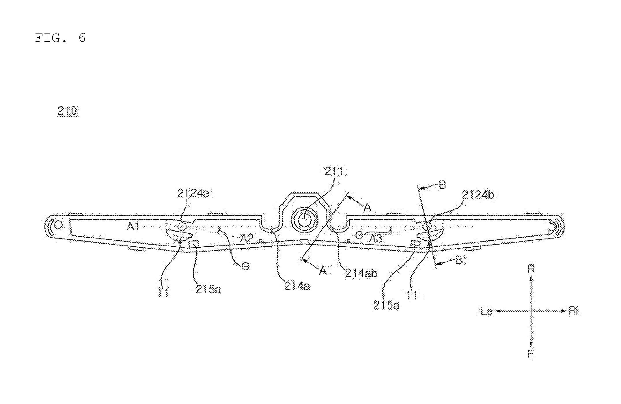
[0037] FIG. 6 is a bottom view of a steam nozzle body of FIG. 4.
[0038] FIG. 7 is a cross-sectional view, taken along line A-A' in FIG. 6.
[0039] FIG. 8 is a cross-sectional view, taken along line B-B' in FIG. 6.
[0040] FIG. 9 is an exploded perspective view of a steam nozzle in a dishwasher according to another embodiment of the present disclosure.
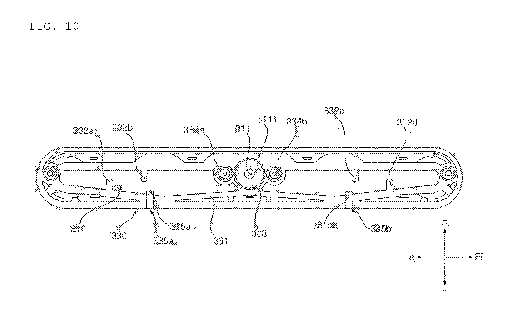
[0041] FIG. 10 is a bottom view of a steam nozzle of a dishwasher according to another embodiment of the present disclosure.
[0042] FIG. 11 is a perspective view of a steam nozzle body in a dishwasher according to another embodiment of the present disclosure.
DETAILED DESCRIPTION
[0043] The advantages and features of the present disclosure and methods for achieving these will be clarified in detail through embodiments described hereinafter in conjunction with the accompanying drawings. However, embodiments of the present disclosure may, however, be implemented in many different forms and should not be construed as being limited to the embodiments set forth herein. Rather, these embodiments are provided so that this disclosure will be thorough and complete, and will fully convey the scope of the disclosure to those skilled in the art and are defined by the claim coverage of the present disclosure.
[0044] Hereinafter, a dishwasher according to embodiments of the present disclosure will be described with reference to the accompanying drawings.
[0045] Hereinafter, front (F)/rear (R)/left (Le)/right (Ri)/up (U)/down (D) may be defined as illustrated in the drawings. However, these are merely illustrative and may also be defined to be different therefrom.
[0046] FIG. 1 is a schematic structural view of a dishwasher according to an embodiment of the present disclosure.
[0047] FIG. 2 is a view illustrating a configuration of a dishwasher according to an embodiment of the present disclosure.
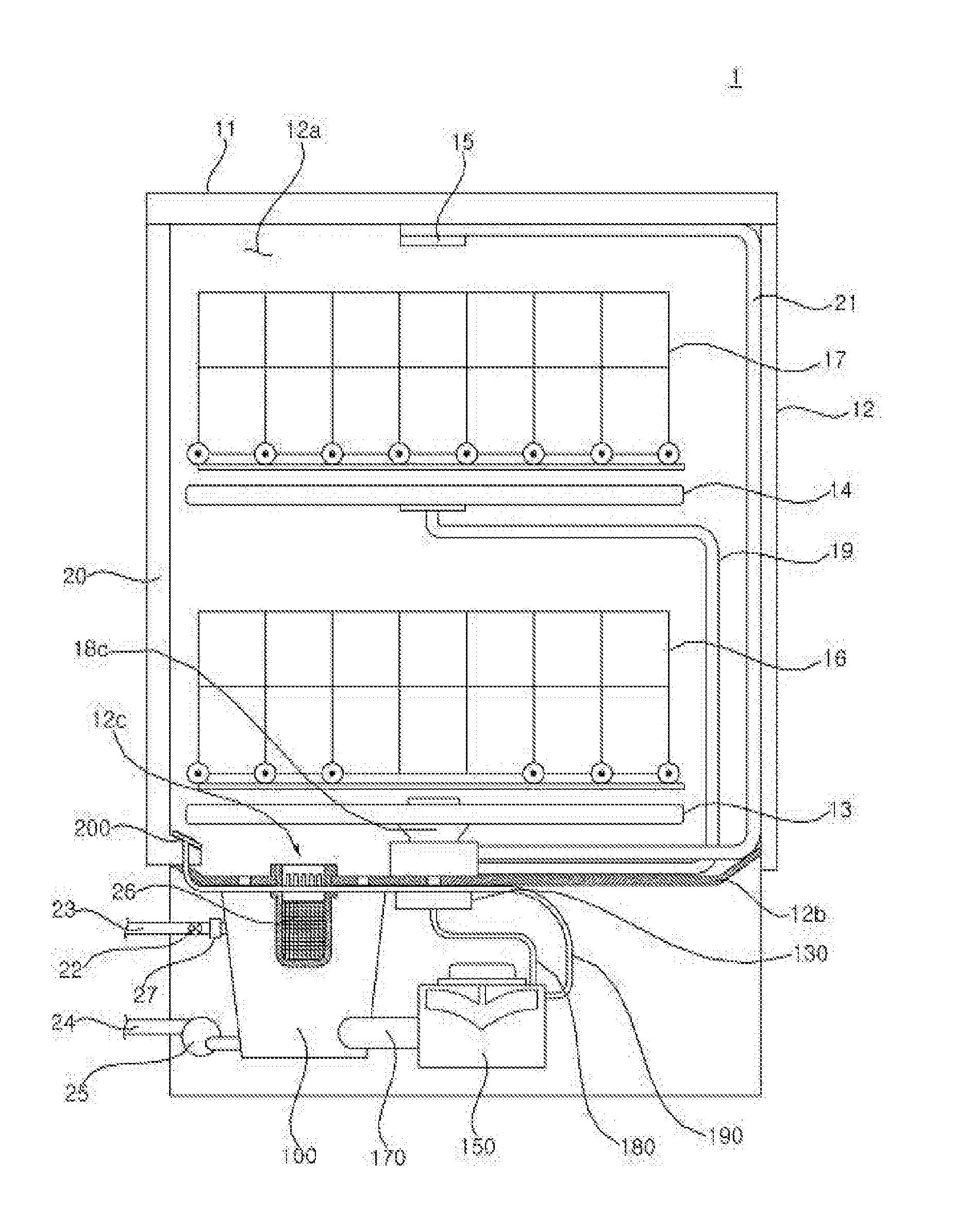
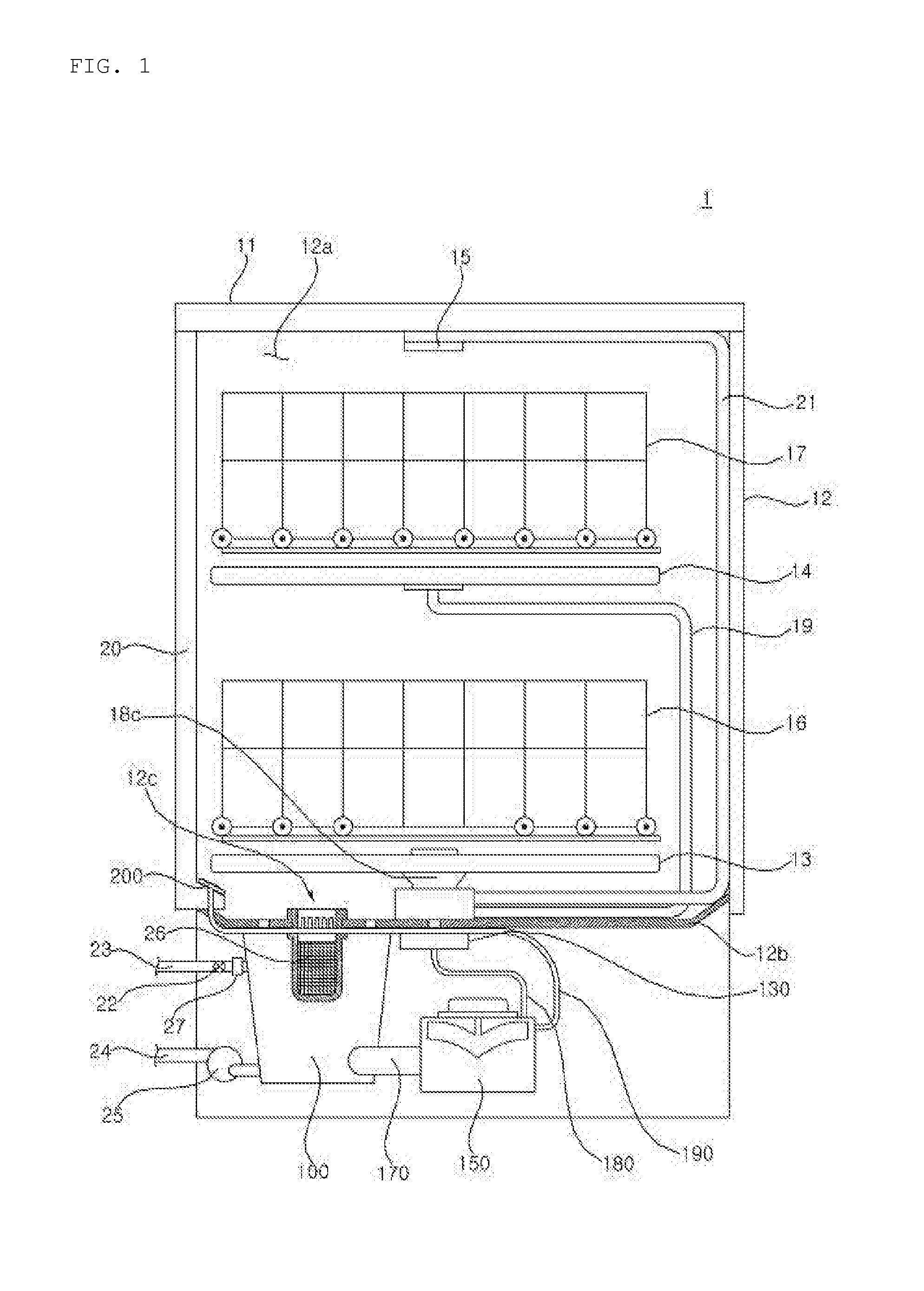
[0048] The dishwasher 1 according to the embodiment of the present disclosure includes a case 11 forming an outer appearance, a tub 12 provided inside the case 11 to form a washing chamber 12a in which an object to be cleaned (or cleaning target) is accommodated, a door 20 provided on a front surface of the tub 12 to open and close the washing chamber 12a, a sump 100 disposed below the tub 12 to store washing water, a plurality of spray arms 13, 14, and 15 spraying washing water into the tub 12, a washing pump 150 supplying washing water stored in the sump 100 to the plurality of spray arms 13, 14 and 15 and generating steam, a steam nozzle 200 provided at the door and spraying steam generated by the washing pump 150 to the washing chamber 12a, a steam hose 190 connecting the washing pump 150 and the steam nozzle 200, and a changeover valve 130 disposed at the sump 100 and distributing washing water to the plurality of spray arms 13, 14, and 15.
[0049] Inside the case 11, the tub 12 in which the dishes to be washed are accommodated may be disposed. The case 11 may accommodate the tub 12 and all of the components of the dishwasher 1.
[0050] The tub 12 has a hexahedral shape in which a front side is open to form a washing chamber 12a therein. A communication hole 12c through which the washing water flows into the sump 100 is formed on the bottom 12b of the tub 12. The washing chamber 12a includes a plurality of racks 16, 17 for receiving the cleaning target. The plurality of racks 16 and 17 includes a lower rack 16 disposed at a lower portion of the washing chamber 12a and an upper rack 17 disposed at an upper portion thereof. The lower rack 16 and the upper rack 17 may be disposed to be spaced apart from each other vertically and slidably drawn out forwards from the tub 12.
[0051] The plurality of spray arms 13, 14, and 15 are arranged in a vertical direction. The plurality of spray arms 13, 14, and 15 includes a low spray arm 13 disposed at a lowermost end and spraying washing water upwards toward the lower rack 16, an upper spray arm 14 disposed above the low spray arm 13 and spraying washing water upwards toward the upper rack 17, and a top spray arm 15 disposed at an upper end of the washing chamber 12a, which is above the upper spray arm 14, and spraying washing water downwards.
[0052] The plurality of spray arms 13, 14, and 15 are supplied with washing water from the washing pump 150 through a plurality of spray arm connecting flow paths 18, 19, and 21. The plurality of spray arm connecting flow paths 18, 19, and 21 include a low spray arm connecting flow path 18 connected to the low spray arm 13, an upper spray arm connecting flow path 19 connected to the upper spray arm 14, and a top spray arm connecting flow path 21 connected to the top spray arm 15.
[0053] The sump 100 is disposed below the bottom 12b of the tub 12 to collect washing water. The sump 100 is connected to a water supply flow path 23 through which washing water supplied from an external water source flows. The water supply flow path 23 includes a water supply valve 22 for controlling washing water supplied from an external water source. When the water supply valve 22 is opened, the washing water supplied from the external water source flows into the sump 100 through the water supply flow path 23. The water supply flow path 23 includes a flow meter 27 for measuring a flow rate of the washing water flowing into the sump 100 through the water supply flow path 23.
[0054] The sump 100 is connected to a drainage flow path 24 for guiding the stored washing water to the outside of the dishwasher 1. The drainage flow path 24 includes a drain pump 25 for draining the washing water in the sump 100 through the drainage flow path 24. When the drain pump 25 is driven, the washing water stored in the sump 100 flows to the outside of the case 11 through the drainage flow path 24.
[0055] The filter 26 is installed in the communication hole 12c to filter out soil from the washing water moving from the tub 12 to the sump 100.
[0056] The washing pump 150 supplies the washing water stored in the sump 100 to at least one of the plurality of spray arms 13, 14, and 15. The washing pump 150 is connected to the changeover valve 130 and the washing water supply flow path 180. When the washing pump 150 is driven, the washing water stored in the sump 100 flows into the washing pump 150 through a water collecting flow path (or water catchment flow path) 170 and then is sent to the changeover valve 130 through the washing water supply flow path 180.
[0057] The washing pump 150 may heat the washing water transferred to the washing water supply flow path 180. The washing pump 150 heats the washing water stored therein to generate steam. The washing pump 150 is connected to the steam hose 190. The steam generated by the washing pump 150 is supplied to the steam nozzle 200 through the steam hose 190.
[0058] The washing pump 150 is installed on one side of the sump 100. As the washing pump 150, any one of the known pumps may be used, and thus, detailed description thereof will be omitted here.
[0059] A heater 140 is coupled to a lower side of the washing pump 150 to heat the washing water in the washing pump 150. When the washing pump 150 operates, the heater 140 heats the washing water flowing in the washing pump 150 to generate hot water. When the washing pump 150 is stopped, the heater 140 heats the washing water stored in the washing pump 150 to generate steam.
[0060] The hot water generated by the heater 140 is sprayed into the tub 12 through at least one of the plurality of spray arms 13, 14, and 15. The steam generated by the heater 140 flows along the steam hose 190 and is discharged into the tub 12 through the steam nozzle 200.
[0061] The steam nozzle 200 is provided at a lower end of the door 20 to spray steam into the washing chamber 12a. The steam sprayed from the steam nozzle 200 acts on the cleaning target accommodated in the lower rack 16 and/or the upper rack 17. Details of the steam nozzle 200 will be described later with reference to FIG. 3 and the following figures.
[0062] The changeover valve 130 selectively connects the sump 100 to at least one of the plurality of spray arms 13, 14, and 15. The changeover valve 130 selectively supplies the washing water pressure-fed by the washing pump 150 to at least one of the low spray arm 13, the upper spray arm 14, and the top spray arm 15. The changeover valve 130 selectively connects the washing water supply flow path 180 to at least one of the plurality of spray arm connecting flow paths 18, 19 and 21.
[0063] A check valve 175 is disposed between the sump 100 and the washing pump 150 and opened in a direction from the sump 100.toward the washing pump 150. The check valve 175 is opened to allow the washing water to flow from the sump 100 to the washing pump 150 and closed so that steam may not flow from the washing pump 150 to the sump 100. The check valve 175 is opened as a lower portion rotates with respect to an upper portion thereof. The check valve 175 is disposed inside the water collecting flow path 170 or connected between the water collecting flow path 170 and the washing pump 150 to open and close the water collecting flow path 170.
[0064] The check valve 175 is closed when the heater 140 generates steam. The check valve 175 is opened when the washing pump 150 operates to allow the washing water to flow, and is closed when the washing pump 150 stops and the washing water does not flow. The check valve 175 is opened by a flow pressure of the washing water of the washing pump 150. According to an embodiment, the check valve 175 may be a solenoid valve that is opened or closed by an electronic signal.
[0065] The check valve 175 is formed to allow the washing water to flow from the washing pump 150 to the sump 100 even in a closed state when the drain pump 25 operates.
[0066] FIG. 3 is an exploded perspective view of a steam nozzle of a dishwasher according to an embodiment of the present disclosure.
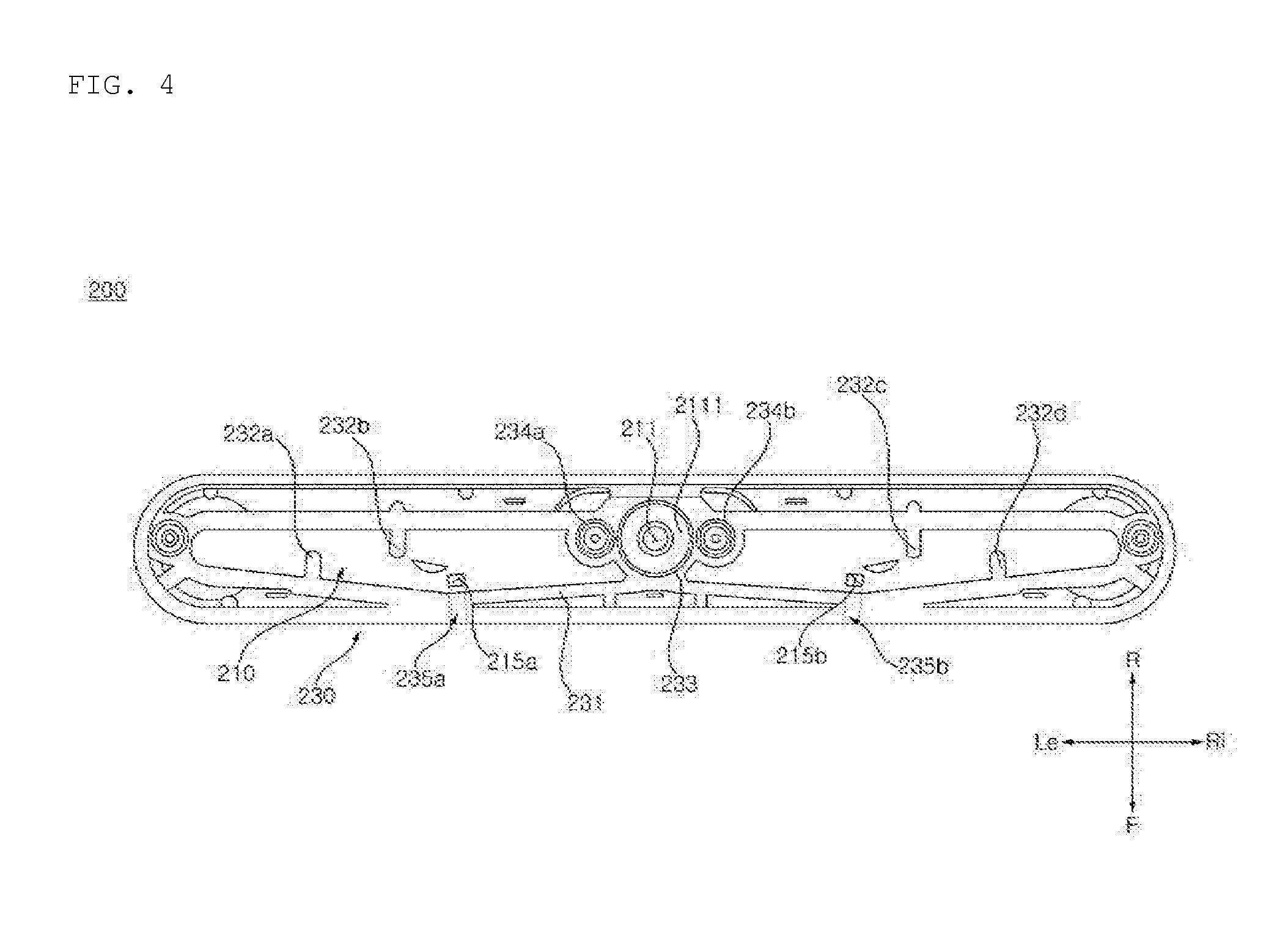
[0067] FIG. 4 is a bottom view of a steam nozzle of a dishwasher according to an embodiment of the present disclosure.
[0068] Referring to FIG. 3, the steam nozzle 200 includes a steam nozzle body 210 extending to the left and right with respect to a central portion where a steam inlet 211 is formed and having a steam accommodating portion 210a, an upper case 220 coupled to the steam nozzle body 210 to form the steam accommodating portion 210a, a lower case 230 coupled to the upper case 220 to form an internal space accommodating the steam nozzle body 210, and a steam nozzle cover 240 coupled to the upper case 220 and having steam spray orifices 2411a, 2411b, 2421a, and 2421b.
[0069] The steam nozzle body 210 may include the steam accommodating portion 210a in which steam and/or water is accommodated. The steam accommodating portion 210a may be formed by coupling the steam nozzle body 210 and the upper case 220.
[0070] In order to spray steam accommodated in the steam accommodating portion 210a to the washing chamber 12a formed in the tub 12, the steam nozzle body 210 may include a pair of first steam sprayers 212a and 212b horizontally. The pair of first steam sprayers 212a and 212b may be provided symmetrically in the steam nozzle body 210 horizontally. The pair of first steam sprayers 212a and 212b may be disposed at positions spaced apart from the steam inlet 211 by a certain distance.
[0071] The pair of first steam sprayers 212a and 212b may include tunnel flow paths 2121a and 2121b penetrating through lower ends of the first steam sprayers 212a and 212b, respectively. One end of each of the tunnel flow paths 2121a and 2121b is opened toward a central portion of the steam nozzle body 210 in which the steam inlet 211 is formed and the other end thereof is opened toward an end portion of the steam nozzle body 210 in which the second steam sprayers 213a and 213b are disposed so that steam passing through the tunnel flow paths 2121a and 2121b may flow into the second steam sprayers 213a and 213b.
[0072] The steam nozzle body 210 includes a pair of second steam sprayers 213a and 213b provided horizontally at positions farther from the steam inlet 211 than the pair of first steam sprayers 212a and 212b. The pair of second steam sprayers 213a and 213b may be disposed at positions symmetrical to each other horizontally at the steam nozzle body 210. The pair of second steam sprayers 213a and 213b may be disposed at a certain distance from the steam inlet 211, respectively. The pair of second steam sprayers 213a and 213b may be provided at both left and right ends of the steam nozzle body 210.
[0073] The steam nozzle body 210 may have coupling recesses 214a and 214b which are dented inward from a rear side of the steam nozzle body 210. In the steam nozzle body 210, widths of flow paths in the steam accommodating portion 210a at positions where the coupling holes 214a and 214b are formed may be narrowed to have a neck shape.
[0074] The coupling recesses 214a and 214b may have a semicircular shape when viewed from above. Details of the steam nozzle body 210 will be described later with reference to FIG. 6 and the following figures.
[0075] The upper case 220 may have a bar type in which a length in a left-right direction is longer than a width in a front-rear direction. A lower end of the upper case 220 may have a shape corresponding to a shape of the steam nozzle body 210 and guide a coupling position of the steam nozzle body 210.
[0076] The upper case 220 may be coupled with the steam nozzle body 210 to form the steam accommodating portion 210a. The upper case 220 may include a pair of first upper case holes 222a and 222b into which a pair of first steam sprayers are inserted, respectively. The upper case 220 may include a pair of second upper case holes 223a and 223b into which a pair of second steam sprayers 213a and 213b are inserted, respectively.
[0077] In the upper case 220, a pair of first upper case holes 222a and 222b, into which first steam spray orifices 2124a and 2124b of the pair of first steam sprayers 212a and 212b are inserted, respectively, may be provided at positions corresponding to the first steam spray orifices 2124a and 2124b.
[0078] In the upper case 220, a pair of second upper case holes 223a and 223b, into which second steam spray orifices 2134a and 2134b of the pair of second steam sprayers 213a and 213b are inserted, respectively, may be provided at positions corresponding to the second steam spray orifices 2134a and 2134b.
[0079] Accordingly, the pair of first steam sprayers 212a and 212b may penetrate through the first upper case holes 222a and 222b of the upper case 220 and spray steam into the washing chamber 12a formed in the tub 12. Also, the pair of second steam sprayers 213a and 213b may penetrate through the second upper case holes 223a and 223b of the upper case 220 and spray steam into the washing chamber 12a formed in the tub 12.
[0080] In the upper case 220, a coupling portion to be coupled with the steam nozzle body 210 may have a E shape, so that the steam nozzle body 210 may be insertedly coupled. The coupling portion of upper case 220 may be formed of an elastic material such as rubber to enhance airtightness when the coupling portion is coupled with the steam nozzle body 210.
[0081] The upper case 220 may include a plurality of coupling rings provided at a plurality of positions and coupled with protrusions formed at the steam nozzle body 210 to maintain coupling between the upper case 220 and the steam nozzle body 210. The upper case 220 may have coupling rings corresponding to the number of positions corresponding to coupling protrusions formed on the steam nozzle body 210.
[0082] The upper case 220 includes a seating portion 221 corresponding to a shape of the steam nozzle cover 240 so that the steam nozzle cover 240 may be partially inserted and coupled. The upper case 220 may have a plurality of coupling recesses into which the coupling rings of the steam nozzle cover 240 are inserted.
[0083] The lower case 230 may have a seating portion 231 corresponding to the shape of the steam nozzle body 210 so that the steam nozzle body 210 may be seated thereon. The lower case 230 may be coupled to the upper case 220 to form an internal space in which the steam nozzle body 210 is accommodated.
[0084] The lower case 230 may have the seating portion 231 in a shape in which the steam nozzle body 210 is projected on a lower plane of the steam nozzle body 210 so that the steam nozzle body 210 is vertically coupled.
[0085] The seating portion 231 may be opened downward so that the lower case 230 communicates with the inside of the washing chamber 12a. Accordingly, the water in the lower case 230 may be introduced into the washing chamber 12a.
[0086] In the lower case 230, stoppers 232a, 232b, 232c, and 232d for guiding a seating height of the steam nozzle body 210 protrude from the edge of the seating portion 231 to the inner side of the seating portion 231 by a predetermined length to guide a coupling position when the steam nozzle body 210 is coupled. Although not shown, the stoppers 232a, 232b, 232c, and 232d may have a shape traversing a lower end of the lower case 230.
[0087] The lower case 230 may include a steam inlet through hole 233 through which the steam inlet 211 of the steam nozzle body 210 penetrates. The lower case 230 may have the steam inlet through hole 233 having a size corresponding to the steam inlet 211 of the steam nozzle body 210. The steam inlet 211 may penetrate through the steam inlet through hole 233 and may be connected to the steam hose 190 so that steam may be introduced therethrough.
[0088] The lower case 230 may have lower case coupling portions 234a and 234b having a shape corresponding to the coupling recesses 214a and 214b of the steam nozzle body 210.
[0089] The lower case coupling portions 234a and 234b may have a size and shape to fit into the coupling recesses 214a and 214b so as to couple with the coupling recesses 214a and 214b of the steam nozzle body 210.
[0090] The lower case coupling portions 234a and 234b may have a central hole and the coupling portion provided at the upper case 220 may be inserted and coupled thereto.
[0091] The steam nozzle cover 240 may be bar-like shape in which a length in a left-right direction is longer than a width in a front-rear direction. The steam nozzle cover 240 may have a plurality of downwardly protruding coupling protrusions and may be inserted and coupled with coupling holes formed on an upper side of the upper case 220.
[0092] The steam nozzle cover 240 may have a horizontally symmetrical shape.
[0093] The steam nozzle cover 240 may include a pair of first steam cover spray orifices 241a and 241b positioned to correspond to positions of a pair of first steam spray orifices 2122a and 2122b. The steam nozzle cover 240 may include a pair of second steam cover spray orifices 242a and 242b positioned to correspond to positions of a pair of second steam spray orifices 2132a and 2132b.
[0094] The pair of first steam cover spray orifices 241a and 241b have a disc shape as a whole and spray holes 2411a and 2411b formed at the center thereof. Steam may be sprayed from the first steam spray orifices 2122a and 2122b into the washing chamber 12a through the spray holes 2411a and 2411b.
[0095] The pair of second steam cover spray orifices 242a and 242b may have a disc shape as a whole and spray holes 2421a and 2421b formed at the center thereof. Steam may be sprayed from the second steam spray orifices 2132a and 2132b into the washing chamber 12a through the spray holes 2421a and 2421b.
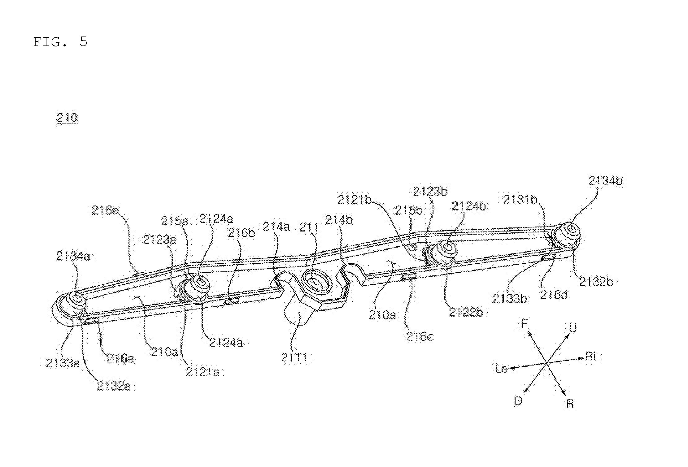
[0096] FIG. 5 is a perspective view of a steam nozzle body in a dishwasher according to an embodiment of the present disclosure.
[0097] FIG. 6 is a bottom view of the steam nozzle body of FIG. 4, FIG. 7 is a cross-sectional view, taken along line A-A' of FIG. 6, and FIG. 8 is a cross-sectional view, taken along line B-B' of FIG. 6.
[0098] Referring to FIGS. 4 and 6, the steam nozzle body 210 may have a bar-like shape in which a length in the left-right direction is longer than a width in the front-rear direction. The steam nozzle body 210 may have a length in the left-right direction, a width in the front-rear direction, and a height in the up-and-down direction.
[0099] The steam nozzle body 210 may have the steam accommodating portion 210a therein to temporarily accommodate steam or water. The steam accommodating portion 210a may accommodate steam or water introduced into the steam nozzle body 210 through the steam inlet 211.
[0100] Front/rear and lower sides of the steam accommodating portion 210a may be partitioned by the steam nozzle body 210 and an upper side thereof may be partitioned by the upper case 220. That is, the steam accommodating portion 210a may be defined as an internal space formed as the steam nozzle body 210 and the upper case 220 are coupled.
[0101] Since the steam accommodating portion 210a serves as a flow path through which steam flows, it may also be referred to as a steam flow path.
[0102] The steam nozzle body 210 has the steam inlet 211 formed at a central portion thereof, and steam may be introduced from the washing pump 150. The steam nozzle body 210 may include the steam inlet 211 and a portion in which a width in a front-rear direction is larger than other portions of the steam nozzle body 210 maybe referred to as a `central portion`.
[0103] The steam nozzle body 210 may be shaped to extend horizontally from the center. The steam nozzle body 210 is provided to have a horizontally symmetrical shape with respect to the central portion so that the steam introduced into the steam inlet 211 may flow uniformly to the left and right. That is, the steam nozzle body 210 may be provided to be horizontally symmetrical with respect to a virtual plane traversing the center of the steam inlet 211 to extend forward/backward and up and down. Through this, the steam may be uniformly sprayed to the inside of the tub 12 through the steam sprayers.
[0104] The steam nozzle body 210 may include a steam inlet pipe 2111 extending downward by a predetermined length. The steam inlet pipe 2111 may have a hollow cylindrical shape and has the steam inlet 211 formed at the center thereof. The steam inlet pipe 2111 may be connected to the steam hose 190 so that the steam may flow into the steam nozzle body 210.
[0105] The steam inlet pipe 2111 may penetrate through the steam inlet through hole 233 of the lower case 230 and may be coupled to the steam hose.
[0106] The steam nozzle body 210 may include a pair of first steam sprayers 212a and 212b for spraying the steam from the steam accommodating portion 210a into the tub 12 on the right and left sides of the steam nozzle body 210. The left first steam spray hole 2124a and the right first steam sprayer 212b may be provided to be horizontally symmetrical with respect to a plane traversing the centers of the left first steam spray hole 2124a and the right first steam sprayer 212b.
[0107] The left first steam spray hole 2124a may be disposed to be spaced apart from the steam inlet 211 leftward by a first distance. The left first steam spray hole 2124a may be connected to a rear side wall of the steam nozzle body 210.
[0108] The left first steam spray hole 2124a may include a first steam spray orifice 2122a for spraying steam into the washing chamber 12a. An upper end of the left first steam spray hole 2124a may be connected to the first steam spray orifice 2122a and a lower end thereof may include a first steam spray orifice lower end 2123a connected to a lower side surface of the steam nozzle body 210.
[0109] The first steam spray orifice 2122a may be a hollow cylindrical spray tube extending vertically, and a first steam spray hole 2124a through which steam is sprayed may be formed at the center thereof.
[0110] Referring to FIG. 8, one end of the first steam spray orifice 2122a communicates with the tunnel flow path 2121a of the first steam sprayer 212a and the other end thereof is opened into the tub 12 so that a portion of steam introduced into the tunnel flow path 2121a may be sprayed into the tub 12 through the first steam spray orifice 2122a.
[0111] The first steam spray orifice 2122a may penetrate through a first upper case hole 222a of the upper case 220 and communicate with the washing chamber 12a.
[0112] The first steam spray orifice 2122a may be inserted and coupled to the first upper case hole 222a.
[0113] As illustrated in FIG. 8, in the first steam spray orifice 2122a, a circular first steam spray hole 2124a through which steam is sprayed may have a predetermined diameter.
[0114] Although not shown, the first steam spray hole 2124a may have a shape other than the circular shape and may be formed to have a gradually decreasing diameter. Accordingly, it is possible to control a region in which the steam sprayed from the first steam spray orifice 2122a is sprayed to the washing chamber 12a. For example, the diameter of the first steam spray hole 2124a decreases toward the side communicating with the washing chamber 12a from the side connected to the tunnel flow path 2121a so that the steam may reach a further inside of the washing chamber 12a.
[0115] Referring to FIG. 8, in the first steam sprayer 212a, a sectional area of the tunnel flow path 2121a may be larger than a-sectional area of the flow path of the first steam spray orifice 2122a. That is, the sectional area of the tunnel flow path 2121a may be larger than the sectional area of the first steam spray hole 2124a.
[0116] A portion of the steam introduced into the tunnel flow path 2121a may be sprayed into the washing chamber 12a through the first steam spray orifice 2122a and the rest may be introduced into the second steam spray orifice 213a through the tunnel flow path 2121a, and thus, steam spray at the second steam sprayer 213a may be improved.
[0117] The first steam spray orifice lower end 2123a may have a cylindrical shape so that the tunnel flow path 2121a may be formed. The tunnel flow path 2121a may penetrate through the first steam spray orifice lower end 2123a in a left-right direction. Here, the tunnel flow path 2121a may extend in the left-right direction in a strict sense or may extend at a certain angle with respect to the left-right direction.
[0118] A cross-section of the tunnel flow path 2121a may have a quadrangular shape. In the tunnel flow path 2121a, a lower side surface of the steam nozzle body 210 forms a lower side surface of the tunnel flow path 2121a so that resistance when the steam of the steam accommodating portion 210a flows into the tunnel flow path 2121a may be reduced.
[0119] Although not shown, the tunnel flow path 2121a may have various sectional areas such as a polygonal shape or an elliptical shape, in addition to the quadrangular shape.
[0120] The corner of an entrance of the tunnel flow path 2121a is rounded to reduce flow path resistance applied to the steam flowing into the tunnel flow path 2121a.
[0121] Referring to FIG. 6, the tunnel flow path 2121a may be formed such that a virtual line Al connecting the centers of the pair of first steam sprayers 212a and 212b and directions A2 and A3 in which the tunnel flow paths 2121a and 2121b extend are at a predetermined angle (.theta.). For example, the predetermined angle (.theta.) may be an angle less than 30.degree..
[0122] Accordingly, since the inlet of the tunnel flow path 2121a is formed to correspond to a flow direction of the steam in the steam accommodating portion 210a, a flow path resistance applied when the steam flows into the tunnel flow path 2121a may be reduced and the amount of steam flowing into the tunnel flow path 2121a may increase.
[0123] Referring to FIGS. 5 and 6, in the present embodiment, the steam introduced into the steam inlet 211 is introduced to a flow path between the coupling holes 214a and 214b and the front wall of the steam nozzle body 210. Inner ends of the tunnel flow paths 2121a and 2121b are formed to face the flow path near the coupling holes 214a and 214b through which the steam passes and may be formed to correspond to the flow direction of the steam.
[0124] In addition, when the tunnel flow paths 2121a and 2121b are at the certain angle (.theta.) as illustrated in FIG. 6, the steam nozzle 200 may be easily manufactured. For example, the steam nozzle body 210 may be manufactured using a slide-type mold method, and in this case, the steam nozzle body 210 may be easily manufactured when the tunnel flow paths 2121a and 2121b are at the certain angle (.theta.) horizontally as illustrated in FIG. 6. A sectional area of an end portion of the tunnel flow path 2121a adjacent to the steam inlet 211 may be greater than a sectional area of an end portion of the tunnel flow path 2121a adjacent to the second steam sprayer 213a. Accordingly, workability of the steam nozzle body 210 may be improved.
[0125] The description of the left first steam sprayer 212a may be applied to the right first steam sprayer 212b. The right first steam sprayer 212b may be shaped to be symmetrical with the left first steam sprayer 212a.
[0126] The left second steam sprayer 213a may be disposed to be spaced apart from the steam inlet 211 to the left by a second distance. The second distance may be longer than the first distance.
[0127] The left second steam sprayer 213a may be disposed at a left end of the steam nozzle body 210.
[0128] The left second steam sprayer 213a may include a second steam spray orifice 2132a for spraying steam into the washing chamber 12a. The left second steam sprayer 213a may include the second steam spray orifice 2132a spraying steam into the washing chamber 12a. The left second steam sprayer 213a may include a second steam sprayer lower end 2133a whose upper end is connected to the second steam spray orifice 2132a and lower end is connected to a lower side surface of the steam nozzle body 210.
[0129] The left second steam sprayer 213a may include a second steam sprayer inlet 2131a through which steam flows from the steam accommodating portion 210a to the second steam sprayer 213a.
[0130] The second steam spray orifice 2132a, which is a hollow cylindrical spray pipe extending vertically, may have a second steam spray hole 2134a formed at a center thereof and allowing steam to be sprayed therethrough.
[0131] One end of the second steam spray orifice 2132a communicates with the second steam sprayer inlet 2131a of the second steam sprayer 213a and the other end thereof is opened to the inside of the tub 12 so that steam introduced to the second steam sprayer inlet 2131a may be sprayed into the tub 12 through the second steam spray orifice 2132a.
[0132] The second steam spray orifice 2132a may penetrate through the second upper case hole 223a of the upper case 220 and communicate with the washing chamber 12a. The second steam spray orifice 2132a may be inserted and coupled to the second upper case hole 223a.
[0133] In the second steam spray orifice 2132a, the circular second steam spray hole 2134a through which steam is sprayed may have a certain diameter.
[0134] Although not shown, the second steam spray hole 2134a may have a shape other than the circular shape and may be formed such that a diameter thereof is gradually reduced. Accordingly, it is possible to control a region in which the steam sprayed from the second steam spray orifice 2132a is sprayed into the washing chamber 12a. For example, the diameter of the second steam spray hole 2134a decreases toward the side communicating with the washing chamber 12a from the side connected to the tunnel flow path 2121a so that the steam may reach a further inner side of the washing chamber 12a.
[0135] Referring to FIGS. 4 and 8, in the second steam sprayer 213a, a sectional area of the second steam sprayer inlet 2131a may be greater than a sectional area of a flow path of the second steam spray hole 2134a. That is, the sectional area of the second steam sprayer inlet 2131a may be greater than the sectional area of the second steam spray hole 2134a.
[0136] Accordingly, when a flow rate is constant, a flow velocity is in inverse proportional to the sectional area, and thus, when the steam introduced into the second steam sprayer inlet 2131a is sprayed through the second steam spray hole 2134a, the flow rate of steam may be increased. Therefore, the steam spray at the second steam sprayer 213a may be improved.
[0137] The second steam sprayer lower end 2133a may have a cylindrical shape and opened toward the center of the steam nozzle body 210 to form the second steam sprayer inlet 2131a.
[0138] A cross-section of the second steam sprayer inlet 2131a may have a quadrangular shape. As a lower side surface of the steam nozzle body 210 forms a lower side surface of the second steam sprayer inlet 2131a, whereby resistance applied when the steam of the steam accommodating portion 210a is introduced to the second steam sprayer inlet 2131a may be reduced.
[0139] Although not shown, the second steam sprayer inlet 2131a may have various sectional areas such as a polygonal shape or an elliptical shape in addition to the quadrangular shape.
[0140] The corner of an entrance of the second steam sprayer inlet 2131a is rounded to reduce resistance applied to the steam introduced into the second steam sprayer inlet 2131a.
[0141] The right second steam sprayer 213b may be provided symmetrically with the left second steam sprayer 213a. As for the right second steam sprayer 213b, the description of the left second steam sprayer 213a may be applied.
[0142] The steam nozzle body 210 may have a pair of drain holes 215a and 215b formed on the left and right and allowing water in the steam accommodating portion 210a to be discharged therethrough. The drain holes 215a and 215b may be holes formed on a lower surface and/or a front surface of the steam nozzle body 210.
[0143] Referring to FIGS. 6 and 7, the left drain hole 215a may be provided between the steam inlet 211 and the left first steam spray hole 2124a.
[0144] The left drain hole 215a may be formed at a flow path between the first steam sprayer 212a and a front wall of the steam nozzle body 210. That is, the left drain hole 215a may be formed near the first steam discharging end 212a, which is a portion where the width of the steam accommodating portion 210a in the front-rear direction is reduced.
[0145] The right drain hole 215b may be provided symmetrically with the left drain hole 215a. Regarding the right drain hole 215b, the description of the left drain hole 215a may be applied.
[0146] When the steam is introduced from the washing pump 150 through the steam inlet 211, washing water, as well as the steam, may also be introduced together to the steam nozzle 200. The water introduced to the steam nozzle 200 may be discharged into the tub 12 through the drain holes 215a and 215b formed as described above by gravity. The steam having a density lower than that of water may be sprayed from the first steam sprayers 212a and 212b and the second steam sprayers 213a and 213b of the steam nozzle 200.
[0147] Referring to FIG. 4, the lower case 230 may include drain recesses 235a and 235b having shapes corresponding to the drain holes 215a and 215b of the steam nozzle body 210. The drain recesses 235a and 235b may have a width corresponding to positions corresponding to the drain holes 215a and 215b.
[0148] Alternatively, drain holes may be formed at the lower case 230 to correspond to the drain holes 215a and 215b.
[0149] Accordingly, water may be discharged from the steam accommodating portion 210a into the tub 12.
[0150] The steam nozzle body 210 may include a plurality of coupling protrusions 216a to 216f protruding outward from a front wall or a rear wall of the steam nozzle body 210. Each of the plurality of coupling protrusions 216a to 216f may be coupled with a coupling portion provided in the upper case 220 or with a coupling portion provided at the lower case 230. Accordingly, the steam nozzle body 210 may be coupled with the upper case 220 or the lower case 230.
[0151] Referring to FIGS. 6 and 7, the steam nozzle body 210 may have a shape in which a width a flow path is narrowed from the first steam sprayer to the second steam sprayer. That is, the steam nozzle body 210 may have a shape in which the width of the steam accommodating portion 210a in the front-rear direction is narrowed from the first steam sprayer to the second steam sprayer.
[0152] The steam nozzle 200 configured as described above is configured such that the steam introduced into the steam inlet 211 is effectively transferred to the first steam sprayers 212a and 212b and the second steam sprayers 213a and 213b, whereby steam may be uniformly sprayed from both ends of the nozzle 200.
[0153] In particular, the tunnel flow paths 2121a and 2121b provided at the first steam sprayers 212a and 212b may improve flow of the steam introduced into the second steam sprayers 213a and 213b, resultantly improving steam spray at the second steam sprayers 213a and 213b.
[0154] In the case of the first steam sprayers 212a and 212b, a distance from the steam inlet 211 is closer to that of the second steam sprayers 213a and 213b so that the steam pressure-fed with a high pressure by the washing pump 150 may be easily spread through the first and second steam sprayers 212a and 212b. In contrast, in the case of the second steam sprayers 213a and 213b, a distance from the steam inlet 211 is farther than the first steam sprayers 212a and 212n, the first steam sprayers 212a and 212b are positioned between the steam inlet 211 and the second steam sprayers 213a and 213b, and a steam flow path is provided such that an introduction to the first steam sprayers 212a and 212b is easy, so that a steam spray amount from the second steam sprayers 213a and 213b is not uniform.
[0155] Thus, by forming the tunnel flow paths 2121a and 2121b at the first steam sprayers 212a and 212b, the steam may be uniformly sprayed from the first steam sprayers 212a and 212b and the second steam sprayers 213a and 213b.
[0156] FIG. 9 is an exploded perspective view of a steam nozzle in a dishwasher according to another embodiment of the present disclosure.
[0157] FIG. 10 is a bottom view of a steam nozzle of a dishwasher according to another embodiment of the present disclosure.
[0158] Hereinafter, a steam nozzle 300 of a dishwasher according to another embodiment of the present disclosure will be described with reference to FIG. 9 and the following figures, and here, only parts different from those of the steam nozzle of the dishwasher according to the embodiment of the present disclosure described above will be described.
[0159] In the upper case 320, a pair of first upper case holes 322a and 322b, into which a first steam spray orifice 3122a of a pair of first steam spray orifices 312a and 312b is inserted, may be provided at a position corresponding to the first steam spray orifice 3122a. In the upper case 320, a pair of second upper case holes 323a and 323b, into which a second steam spray orifice 3132a of a pair of second steam spray orifices 313a and 313b is inserted, may be provided at a position corresponding to the second steam spray orifice 3132a.
[0160] The upper case 320 may have a coupling portion 323 for coupling with the steam nozzle body 310. The coupling portion 323 may have a shape corresponding to the shape of the steam nozzle body 310.
[0161] A cross-section of the coupling portion 323 may have a E shape so that the steam nozzle body 310 may be partially inserted into the coupling portion 323 so as to be coupled. The upper case 320 may have an elastic member such as rubber in the coupling portion 323 to enhance airtightness when coupled with the steam nozzle body 310.
[0162] The upper case 320 may include a plurality of coupling rings 324 which are caught by protrusions formed at the steam nozzle body 310 so as to maintain coupling between the upper case 320 and the steam nozzle body 310. The upper case 320 may have the number of coupling rings 324 corresponding to positions corresponding to the coupling protrusions formed on the steam nozzle body 310.
[0163] The upper case 320 may have a plurality of coupling recesses into which the coupling rings of the steam nozzle cover 340 are inserted and coupled.
[0164] The upper case 320 may include coupling bosses 325a, 325b, 325c, and 325d, which are inserted and coupled to lower case coupling portions 334a, 334b, 334c, and 334d . The coupling bosses 325a and 325b may be coupled to the lower case coupling portions 334a and 334b through coupling holes 314a and 314b of the steam nozzle body 310. Accordingly, the upper case 320, the steam nozzle body 310, and the lower case 330 may be coupled.
[0165] The description of the low case 230 according to the embodiment of the present disclosure may be applied to the low case 330 as is. However, a seating portion of the lower case 330 may be partially changed in shape corresponding to a shape of the steam nozzle body 310.
[0166] The description of the steam nozzle cover 240 according to an embodiment may be applied as is to the steam nozzle cover 340.
[0167] FIG. 11 is a perspective view of a steam nozzle body in a dishwasher according to another embodiment of the present disclosure.
[0168] The steam nozzle body 310 may have a bar-like shape in which a length in a left-right direction is longer than a width in a front-rear direction, as in the steam nozzle body 210 according to an embodiment overall.
[0169] The steam nozzle body 310 may have a steam accommodating portion 310a on an inner circumference thereof to temporarily accommodate steam or water. That is, the steam accommodating portion 310a may serve as a flow path for discharging steam or water, which has been introduced through the steam inlet 311, through a steam spray orifice.
[0170] The steam nozzle body 310 has the steam inlet 311 at the center thereof, and steam may be introduced from the washing pump 150 therethrough.
[0171] The steam nozzle body 310 may include a steam inlet 311, coupling holes 314a and 314b, and guide ribs 317a to 317f at a central portion thereof.
[0172] The steam nozzle body 310 may have a shape symmetrical horizontally with respect to the central portion. Accordingly, the steam introduced into the steam inlet 311 may be uniformly introduced to the left and right of the steam nozzle body 310 so that the steam may be uniformly sprayed into the tub 12 through a steam sprayer.
[0173] The steam nozzle body 310 may include a steam inlet pipe 3111 extending downward by a predetermined length. The steam inlet pipe 3111 may have a hollow cylindrical shape and have a steam inlet 311 formed at the center thereof. The steam inlet pipe 3111 is connected to the steam hose 190 so that steam may flow into the steam nozzle body 310.
[0174] The steam inlet pipe 3111 may be coupled to the steam hose through a steam inlet through hole 333 of the lower case 330.
[0175] The steam nozzle body 310 includes a pair of first steam sprayers 312a and 312b for spraying the steam in the steam accommodating portion 310a into the tub 12 on the right and left sides of the steam nozzle body 310. The left first steam sprayer 312a and the right first steam sprayer 312b may be provided to be horizontally symmetrical with respect to a plane traversing the centers of the left first steam sprayer 312a and the right first steam sprayer 312b in up-down and front-rear directions.
[0176] The left first steam spray hole 3124a may be disposed to be spaced apart from the steam inlet leftward by a first distance. The left first steam spray hole 3124a may be provided to be separated from a front side wall and a rear side wall of the steam nozzle body 310.
[0177] The left first steam spray hole 3124a may include a first steam spray hole 3122a spraying steam into the washing chamber 12a. The left first steam spray hole 3124a may include a first steam sprayer lower end 3123a having an upper end connected to the first steam spray orifice 3122a and a lower end connected to a lower side surface of the steam nozzle body 310.
[0178] The first steam spray orifice 3122a is a hollow cylindrical spray pipe extending vertically, and a first steam spray hole 3124a through which steam is sprayed may be formed at the center thereof.
[0179] The steam nozzle body 310 may include a flow path encircling the first steam sprayer. The steam nozzle body 310 may include a flow path formed by a lower end 3123a of the first steam sprayer and a front side wall of the steam nozzle body 310. The steam nozzle body 310 may include a flow path formed by a first steam sprayer lower end 3123a and a rear side wall of the steam nozzle body 310.
[0180] The steam nozzle body 310 may protrude backward to correspond to the shape of the first steam sprayer 312a at a position where the first steam sprayer 312a is disposed, to form a flow path bypassing the first steam sprayer 312a.
[0181] One end of the first steam spray orifice 3122a may communicate with a tunnel flow path 3121a of the first steam sprayer 312a and the other end thereof may be opened to the inside of the tub 12 so that a portion of steam introduced into the tunnel flow path 3121a may be sprayed into the tub 12 through the first steam spray orifice 3122a.
[0182] The first steam spray orifice 3122a may communicate with the washing chamber 12a through the first upper case hole 322a of the upper case 320. The first steam spray orifice 3122a may be inserted and coupled to the first upper case hole 322a.
[0183] A sectional area of the tunnel flow path 3121a may be larger than a sectional area of the flow path of the first steam inlet 3122a. The sectional area of the tunnel flow path 3121a may be larger than a sectional area of the first steam spray hole 3124a.
[0184] A portion of the steam introduced into the tunnel flow path 3121a may be sprayed into the washing chamber 12a through the first steam spray orifice 3122a and the rest may be introduced into the second steam sprayer 313a through the tunnel flow path 3121a, thus enhancing steam spray at the second steam sprayer 313a.
[0185] The first steam sprayer lower end 3123a may have a cylindrical shape, and the tunnel flow path 3121a may be formed. The tunnel flow path 3121a may penetrate through the first steam sprayer lower end 3123a in the left-right direction. Here, the tunnel flow path 3121a may extend in the right-left direction in a strict sense or may extend at a predetermined angle with respect to the left-right direction.
[0186] For example, an angle formed by a virtual straight line connecting the center of the left end and the center of the right end with the left-right direction may form a certain angle (.theta.).
[0187] A cross-section of the tunnel flow path 3121a may have a quadrangular shape. In the tunnel flow path 3121a, a lower side surface of the steam nozzle body 310 forms a lower side surface of the tunnel flow path 3121a so that resistance applied when the steam of the steam accommodating portion 310a flows into the tunnel flow path 3121a may be reduced.
[0188] Although not shown, the tunnel flow path 3121a may have various sectional areas such as a polygonal shape or an elliptical shape, in addition to the quadrangular shape.
[0189] The corner of an entrance of the tunnel flow path 3121a is rounded to reduce flow path resistance applied to the steam flowing into the tunnel flow path 3121a.
[0190] A sectional area of an inner end of the tunnel flow path 3121a closer to the steam inlet 311 may be larger than a sectional area of an outer end of the tunnel flow path 3121a closer to the second steam sprayer 313a. Here, since a portion of the steam flowing into the tunnel flow path 3121a is discharged through the steam spray orifice, the amount of steam discharged from the outer end of the tunnel flow path 3121a decreases. Here, by reducing the sectional area of the outer end of the tunnel flow path 3121a, pressure drop of the steam discharged from the outer end of the tunnel flow path 3121a may be reduced and flow of steam may be improved.
[0191] The left second steam sprayer 313a may be disposed to be farther from the steam inlet 311 than the left first steam spray hole 3124a. The left second steam sprayer 313a may be disposed at a left end of the steam nozzle body 310.
[0192] The left second steam sprayer 313a may include a second steam spray orifice 3132a for spraying steam into the washing chamber 12a. The left second steam sprayer 313a may include a second steam sprayer lower end 3133a having an upper end connected to the second steam spray orifice 3132a and a lower end connected to a lower surface of the steam nozzle body 310.
[0193] The left second steam sprayer 313a may include a second steam sprayer inlet 3131a through which steam flows from the steam accommodating portion 310a to the second steam sprayer 313a.
[0194] The second steam spray orifice 3132a may be a hollow cylindrical spray pipe extending vertically. A second steam spray hole 3134a through which steam is sprayed may be formed at the center of the second steam spray hole 3132a.
[0195] The second steam spray orifice 3132a may have one end communicating with the second steam sprayer inlet 3131a of the second steam sprayer 313a and the other end opened to the inside of the tub 12, so that the steam introduced through the second stem sprayer inlet 3131a may be sprayed to the inside of the tub 12 through the second steam spray orifice 3132a.
[0196] The second steam spray orifice 3132a may communicate with the washing chamber 12a through the second upper case hole 323a of the upper case 320. The second steam spray orifice 3132a may be inserted and coupled to the second upper case hole 323a.
[0197] The second steam spray orifice 3132a may be formed at the center of the second steam spray hole 3134a so that the steam may be sprayed through the second steam spray hole 3134a.
[0198] Although not shown, the second steam spray hole 3124a may have a shape other than the circular shape and may be formed to have a gradually decreasing diameter. Accordingly, it is possible to control a region in which the steam sprayed from the second steam spray orifice 3132a is sprayed to the washing chamber 12a. For example, the diameter of the second steam spray hole 3134a decreases toward the side communicating with the washing chamber 12a from the side connected to the tunnel flow path 3121a so that the steam may reach a further inside of the washing chamber 12a.
[0199] Referring to FIG. 11, in the second steam sprayer 313a, a sectional area of the second steam sprayer inlet 3131a may be greater than a sectional area of a flow path of the second steam spray hole 3134a. That is, the sectional area of the second steam sprayer inlet 3131a may be greater than the sectional area of the second steam spray hole 3134a.
[0200] Accordingly, when the steam flowing into the second steam sprayer inlet end 3131a may be sprayed in a further accelerated manner through the second steam spray hole 3134a. Thus, a distance by which the steam sprayed from the second steam sprayer 313a reaches the washing chamber 12a may be increased.
[0201] The second steam sprayer lower end 3133a may have a cylindrical shape and opened toward the center of the steam nozzle body 310 to form the second steam sprayer inlet 3131a.
[0202] The second steam sprayer inlet end 3131a may be formed by a front side wall, a rear side wall, and a lower side surface of the steam nozzle body 310 and the second steam sprayer lower end 3133a. As the lower side surface of the steam nozzle body 310 forms the lower side surface of the second steam sprayer inlet 3131a, resistance applied when the steam from the steam accommodating portion 310a flows into the second steam sprayer inlet 3131a may be reduced.
[0203] Although not shown, the second steam sprayer inlet 3131a may have various sectional areas such as a polygonal shape or an elliptical shape, in addition to the quadrangular shape.
[0204] The corner of an entrance of the second steam sprayer inlet 3131a is rounded to reduce resistance applied to the steam introduced into the second steam sprayer inlet 3131a.
[0205] The steam nozzle body 310 may have a pair of drain holes 315a and 315b formed on the left and right and allowing water in the steam accommodating portion 210a to be discharged therethrough. The drain holes 215a and 215b may be holes formed on a lower surface and/or a front surface of the steam nozzle body 310.
[0206] Referring to FIGS. 6 and 7, the left drain hole 315a may be provided between the steam inlet 311 and the left first steam spray hole 3124a.
[0207] The left drain hole 315a may be formed at a flow path between the first steam sprayer 312a and a front wall of the steam nozzle body 310. That is, the left drain hole 315a may be formed near the first steam discharging end 312a, which is a portion where the width of the steam accommodating portion 310a in the front-rear direction is reduced.
[0208] The left drain hole 315a may be formed at a rear end of the flow path between the first steam sprayer 312a and the front wall of the steam nozzle body 310.
[0209] The right drain hole 315b may be provided symmetrically with the left drain hole 315a. Regarding the right drain hole 315b, the description on the left drain hole 315a may be applied.
[0210] When the steam is introduced from the washing pump 150 through the steam inlet 311, washing water, as well as the steam, may also be introduced together to the steam nozzle 300.
[0211] The water introduced to the steam nozzle 300 may be discharged to the outside of the steam nozzle 300 through the drain holes 315a and 315b by gravity. Meanwhile, the steam having a density lower than that of water may flow along the steam accommodating portion 310a and may be sprayed from the first steam sprayers 312a and 312b and the second steam sprayers 313a and 313b.
[0212] Referring to FIGS. 9 and 10, the lower case 330 may include drain recesses 335a and 335b having shapes corresponding to the drain holes 315a and 315b of the steam nozzle body 310. The drain recesses 335a and 335b may have a width corresponding to positions corresponding to the drain holes 315a and 315b.
[0213] Referring to FIG. 9, the upper case 320 may include drain recesses 326a and 326b having shapes corresponding to the drain holes 315a and 315b of the steam nozzle body 310. The drain recesses 326a and 326b may have a width corresponding to positions corresponding to the drain holes 315a and 315b.
[0214] Although not shown, the lower case 330 may have drain holes formed to correspond to the drain holes 315a and 315b. Although not shown, the upper case 320 may have drain holes formed to correspond to the drain holes 315a and 315b.
[0215] Accordingly, water may be discharged from the steam accommodating portion 310a into the tub 12.
[0216] The steam nozzle body 310 may include a plurality of coupling protrusions 316 protruding outward from the front wall or the rear wall of the steam nozzle body 310. Each of the plurality of coupling protrusions 316 may be coupled with the coupling portion provided on the upper case 320 or with the coupling portion provided on the lower case 330. Accordingly, the steam nozzle body 310 may be coupled with the upper case 320 or the lower case 330.
[0217] Referring to FIG. 11, the steam nozzle body 310 may have a shape in which a width of the flow path is narrowed from the first steam sprayer 312a to the second steam sprayer 313a. That is, the steam nozzle body 310 may have a shape in which the width of the steam accommodating portion 310a in the front-rear direction is narrowed from the first steam sprayer to the second steam sprayer.
[0218] Referring to FIG. 11, the steam nozzle body 310 may have one or more guide ribs 317a to 317f guiding the steam introduced to the steam inlet 311 to the pair of first steam sprayers 312a and 312b.
[0219] For example, the steam nozzle body 310 may include one or more radial guide ribs 317a to 317f based on the steam inlet 311 as a center. Thus, the steam introduced into the steam inlet 311 may be guided to the first steam sprayer 312a.
[0220] The guide ribs 317a to 317f may be plate-shaped ribs adjacent to the steam inlet 311 and extending from the center of the steam inlet 311 in a radial direction by a predetermined length. The guide ribs 317a to 317f may be provided in a shape to be symmetrical horizontally.
[0221] The guide ribs 317a to 317f may include guide ribs 317b and 317e connected to the coupling holes 314a and 314b. The guide ribs 317a to 317f may include guide ribs 317a and 317d provided between the coupling holes 314a and 314b and the front wall of the steam nozzle body 310. The guide ribs 317a to 317f may include guide ribs 317c and 317f provided between the coupling holes 314a and 314b and the rear wall of the steam nozzle body 310.
[0222] The guide ribs 317a to 317f may be provided to have a height corresponding to a height of the side wall of the steam nozzle body 310 so as to be in contact with the upper case 320.
[0223] The steam nozzle body 310 may have a pair of coupling holes 314a and 314b formed on both sides of the steam inlet 311 at the central portion thereof so that coupling bosses 325a and 325b of the upper case 320 may penetrate therethrough so as to be coupled. The coupling holes 314a and 314b may have a diameter corresponding to a size of the coupling bosses 325a and 325b of the upper case 320, so that the coupling bosses 325a and 325b may be inserted into the coupling holes 314a and 314b.
[0224] The coupling holes 314a and 314b may have a hollow cylindrical shape protruding from a lower side surface of the steam nozzle body 310 by a predetermined length. The coupling holes 314a and 314b may have a height extending from the lower side surface of the steam nozzle body 310 to a lower side surface of the upper case 320.
[0225] The coupling bosses 325a and 325b of the upper case 320 may penetrate through the coupling holes 314a and 314b and may be coupled with the lower case coupling portions 334a and 334b. Accordingly, the upper case 320, the steam nozzle body 310, and the lower case 330 may be coupled with each other.
[0226] The steam nozzle body 310 may include a flow path encircling the coupling holes 314a and 314b. The steam nozzle body 310 may include a flow path between the coupling holes 314a and 314b and the front wall of the steam nozzle body 310 and a flow path between the coupling holes 314a and 314b and the rear wall of the steam nozzle body 310. The steam or water flowing into the steam inlet 311 may flow toward the first steam sprayer 312a along the flow paths formed before and after the coupling holes 314a and 314b. Accordingly, flow of the steam moving from the steam inlet 311 to the first steam sprayer 312a and the second steam sprayer 313a may be improved and steam may be effectively sprayed from the steam sprayer.
[0227] In the steam nozzle 300 configured as described above, flow path resistance applied to the steam introduced to the steam inlet 311 and then introduced to the first steam sprayers 312a and 312b may be reduced further than that of the steam nozzle 200.
[0228] That is, the steam or water flowing into the steam inlet 311 through the flow path formed to encircle the coupling holes 314a and 314b may be effectively transferred to the positions where the first steam sprayers 312a and 312b are disposed.
[0229] Also, in the steam nozzle 300, the steam may be effectively introduced to the second steam sprayers 313a and 313b through a bypass flow path provided to encircle the tunnel flow paths 3121a and 3121b and the first steam sprayers 312a and 312b formed at the first steam sprayers 312a and 312b.
[0230] Therefore, the steam may be more uniformly sprayed from the first steam sprayers 312a and 312b and the second steam sprayers 313a and 313b to the washing chamber 12a, enhancing reliability of the steam nozzle 300.
[0231] Specific embodiments have been described but the present disclosure is not limited to the specific embodiments and various modifications may be made without departing from the scope of the present disclosure claimed in the claims, and such modifications should not be individually understood from technical concepts or prospects of the present disclosure.
[0232] While the present disclosure has been particularly shown and described with reference to embodiments thereof, a person skilled in the art will understand that the disclosure is not limited to the disclosed embodiments but may be variously modified within the scope of the present disclosure. Therefore, the scope of the present disclosure should not be limited to the above-described embodiments but should be determined by all changes or modifications derived from the scope of the appended claims and equivalents of the following claims.
* * * * *
D00000
D00001
D00002
D00003
D00004
D00005
D00006
D00007
D00008
D00009
D00010
D00011
XML
uspto.report is an independent third-party trademark research tool that is not affiliated, endorsed, or sponsored by the United States Patent and Trademark Office (USPTO) or any other governmental organization. The information provided by uspto.report is based on publicly available data at the time of writing and is intended for informational purposes only.
While we strive to provide accurate and up-to-date information, we do not guarantee the accuracy, completeness, reliability, or suitability of the information displayed on this site. The use of this site is at your own risk. Any reliance you place on such information is therefore strictly at your own risk.
All official trademark data, including owner information, should be verified by visiting the official USPTO website at www.uspto.gov. This site is not intended to replace professional legal advice and should not be used as a substitute for consulting with a legal professional who is knowledgeable about trademark law.