Electrical Parameters Of Isotopes
MAZURKIEWICZ; PAUL HOWARD ; et al.
U.S. patent application number 16/332817 was filed with the patent office on 2019-08-08 for electrical parameters of isotopes. The applicant listed for this patent is HEWLETT-PACKARD DEVELOPMENT COMPANY, L.P.. Invention is credited to NING GE, HELEN A. HOLDER, PAUL HOWARD MAZURKIEWICZ.
| Application Number | 20190243311 16/332817 |
| Document ID | / |
| Family ID | 62023894 |
| Filed Date | 2019-08-08 |


| United States Patent Application | 20190243311 |
| Kind Code | A1 |
| MAZURKIEWICZ; PAUL HOWARD ; et al. | August 8, 2019 |
ELECTRICAL PARAMETERS OF ISOTOPES
Abstract
An example device includes an isotope portion including a material having at least one isotope, a reaction control portion to cause a chemical reaction including the at least one isotope, and an electrical parameter portion to measure a change in an electrical parameter to determine a change in an amount of the material having the at least one isotope, the electrical parameter to change based on the chemical reaction.
| Inventors: | MAZURKIEWICZ; PAUL HOWARD; (FORT COLLINS, CO) ; GE; NING; (PALO ALTO, CA) ; HOLDER; HELEN A.; (PALO ALTO, CA) | ||||||||||
| Applicant: |
|
||||||||||
|---|---|---|---|---|---|---|---|---|---|---|---|
| Family ID: | 62023894 | ||||||||||
| Appl. No.: | 16/332817 | ||||||||||
| Filed: | October 31, 2016 | ||||||||||
| PCT Filed: | October 31, 2016 | ||||||||||
| PCT NO: | PCT/US2016/059746 | ||||||||||
| 371 Date: | March 13, 2019 |
| Current U.S. Class: | 1/1 |
| Current CPC Class: | G04F 13/00 20130101; G04F 1/02 20130101; G01N 27/045 20130101 |
| International Class: | G04F 1/02 20060101 G04F001/02; G01N 27/04 20060101 G01N027/04 |
Claims
1. A device, comprising: an isotope portion including a material having at least one isotope; a reaction control portion to cause a chemical reaction including the at least one isotope; and an electrical parameter portion to measure a change in an electrical parameter to determine a change in an amount of the material having the at least one isotope, the electrical parameter to change based on the chemical reaction.
2. The device of claim 1, the chemical reaction is an oxidation of the material having the at least one isotope.
3. The device of claim 2, wherein the reaction control portion is to selectively cause the oxidation or reverse the oxidation.
4. The device of claim 1, wherein the electrical parameter is a resistance value associated with the material having the at least one isotope.
5. The device of claim 4, wherein the electrical parameter portion is to measure a current and/or time to change the resistance value by a predetermined amount.
6. The device of claim 1, wherein the at least one isotope includes two isotopes, and wherein the electrical parameter is associated with a ratio of the two isotopes.
7. The device of claim 1, further comprising a memory controller, wherein the memory controller is to access the electrical parameter portion to perform a read operation based on a determined change in the electrical parameter.
8. A method, comprising: measuring an electrical parameter associated with a decaying isotope, the electrical parameter being used to determine a present level of the decaying isotope; comparing the determined present level of the decaying isotope to a reference level of the decaying isotope corresponding to a reference time; and calculating an elapsed time since the reference time based on the determined present level, the reference level and a half-life associated with the decaying isotope.
9. The method of claim 8, wherein the reference time is indicative of an initialization of a device associated with the decaying isotope.
10. The method of claim 9, wherein the elapsed time is used to determine a warranty status of the device associated with the decaying isotope.
11. The method of claim 8, wherein the electrical parameter is a resistance value associated with the decaying isotope.
12. A non-transitory computer-readable storage medium encoded with instructions executable by a processor of a computing system, the computer-readable storage medium comprising instructions to: cause a chemical reaction of a material including at least one isotope; measure an electrical parameter to determine an amount of the material including the at least one isotope, the electrical parameter being based on the chemical reaction; and calculate an isotope level and/or ratio of the at least one isotope.
13. The non-transitory computer-readable storage medium of claim 12, wherein the chemical reaction is an oxidation of the material including the at least one isotope.
14. The non-transitory computer-readable storage medium of claim 12, wherein the instructions to cause a chemical reaction includes instructions to selectively cause the oxidation or reverse the oxidation.
15. The non-transitory computer-readable storage medium of claim 12, wherein the electrical parameter is a resistance value associated with the material including the at least one isotope.
Description
BACKGROUND
[0001] Many elements have isotopes which occur in nature. An element is defined by the number of protons in its nucleus. For example, carbon has 6 protons in its nucleus, nitrogen has 7 protons in its nucleus, and zinc has 30 protons in its nucleus. Some elements have various isotopes with varying number of neutrons in the nucleus. For example, zinc has five stable isotopes that occur in nature with 34, 36, 37, 38 or 40 neutrons.
BRIEF DESCRIPTION OF THE DRAWINGS
[0002] For a more complete understanding of various examples, reference is now made to the following description taken in connection with the accompanying drawings in which:
[0003] FIG. 1 is a schematic illustration of an example device;
[0004] FIG. 2 is a schematic illustration of an example system;
[0005] FIG. 3 is a schematic illustration of another example system;
[0006] FIG. 4 is a flow chart illustrating an example process; and
[0007] FIG. 5 illustrates a block diagram of an example system with a computer-readable storage medium including instructions executable by a processor.
DETAILED DESCRIPTION
[0008] Various examples provide for devices that may be formed using isotopes of elements. In various examples, a memory device may be formed wherein each memory element, or bit, may be formed of at least one isotope. An electrical parameter associated with the isotope may be measured to determine a state of the isotope. For example, electrical resistance of a material containing the isotope may be indicative of the level of the material containing the isotope or a ratio of two materials containing different isotopes. The level or ratio may be changed by a reaction, such as a chemical reaction, thus changing the determined state. The chemical reaction may be an oxidation of the isotope and may be reversible.
[0009] As noted above, various elements may have stable isotopes which occur in nature. The rate of a chemical reaction involving the element may change depending on the isotope of the element used in the reaction. For example, the reactions below illustrate the use of different isotopes of carbon in reactions of methyl bromide and cyanide:
##STR00001##
[0010] The use of different isotopes changes the rate of the reaction, an effect known as the kinetic isotope effect (KIE). In the example above, the rate of the reaction is reduced with the use of carbon 13 when compared to the rate of the reaction using carbon 12. In the example above, KIE may be represented as:
KIE=k.sub.12/k.sub.13=1.082.+-.0.008
[0011] In various examples, various aspects of one or more isotopes may be used to detect or determine an electrical parameter. For example, a rate of reaction may correspond to a change in electrical resistance of the material containing the isotope. In this regard, the level of a material containing an isotope or the ratio of two materials containing different isotopes may be determined based on a measured electrical parameter, such as resistance. For example, a chemical reaction may include oxidation of an isotope. Increased oxidation may result in reduced electrical resistance. Thus, when two materials containing different isotopes are oxidized for the same length of time, due to a faster oxidation of the material with one isotope compared to the material with the other isotope, the electrical resistance of the two materials may be different.
[0012] Thus, isotopic material may be detected in an efficient and cost-effective manner without the use of expensive and bulky equipment, such as mass spectrometers. Further, security may be enhanced with knowledge of material and isotopes used to encode information available and known only to a limited set of entities or users, such as a manufacturer, for example. Additionally, testing or detection of the isotopic material may be performed without any destructive operation that may require, for example, removal of the isotopic material.
[0013] Referring now to the figures, FIG. 1 illustrates an example device with at least one isotope. In the example of FIG. 1, the example device 100 includes an isotope portion 110, a reaction control portion 120 and an electrical parameter portion 130. In various examples, the example device 100 may be implemented on a printed circuit board (PCB).
[0014] The isotope portion 110 may include a material which has at least one isotope. For example, the isotope portion 110 may include a material with a stable isotope of elements such as zinc, molybdenum or nickel, for example. In various examples, in addition to the isotope(s), the material may include other components which may be needed for a reaction involving the isotope(s), for example.
[0015] The reaction control portion 120 may be provided to cause a chemical reaction related to the isotope(s) in the material. For example, the reaction control portion 120 may cause an electrical current to pass through the material in the isotope portion 110, thus causing an oxidation of the material with the isotope(s). In this regard, the reaction control portion 120 may cause oxidation to occur by flowing current in one direction. Similarly, the reaction control portion 120 may cause reversal of the oxidation to occur by flowing the current in the opposite direction. Thus, the reaction control portion 120 may selectively cause the oxidation or reverse the oxidation.
[0016] The electrical parameter portion 130 of the example device 100 of FIG. 1 is provided to measure an electrical parameter associated with the isotope portion 110 or the material having the isotope(s) in the isotope portion 110. In various examples, the measured electrical parameter may be a resistance value associated with the material having the isotope(s). In other examples, the electrical parameter portion 130 may measure a current and/or time to change the resistance value by a predetermined amount, for example.
[0017] In one example, the isotope portion 110 includes a material with a single isotope. As the reaction control portion 120 causes or reverses a chemical reaction such as, for example, oxidation of the material with the single isotope, the level of the material with the isotope may increase or decrease, depending on the direction of the chemical reaction. In turn, this may increase or reduce the resistance value of the material. Thus, the electrical parameter portion 130 may measure a change in resistance, and the change in resistance may be associated with the level of the material with the isotope.
[0018] In other examples, the isotope portion 110 includes a material with at least two isotopes. As the reaction control portion 120 causes or reverses a chemical reaction such as, for example, oxidation of the material, the ratio of two materials with different isotopes may increase or decrease in accordance with KIE described above, depending on the direction of the chemical reaction. In turn, this may increase or reduce the resistance value of the material. Again, the electrical parameter portion 130 may measure a change in resistance, and the change in resistance may be associated with the ratio of materials with the different isotopes.
[0019] Referring now to FIG. 2, an example system a various isotope devices is illustrated. In the example of FIG. 2, the example system 200 may be a memory system which may be implemented in any of a variety of electronic devices. The example system 200 of FIG. 2 provides an example storage system built with isotope devices similar to the example device 100 described above with reference to FIG. 1.
[0020] In the example of FIG. 2, the example system 200 includes a memory device 210 and a memory controller 290 to access the memory device 210. The memory device 210 is provided with an array of devices 220a-n, each of the devices 220a-n being similar to the example device 100 described above with reference to FIG. 1.
[0021] In the illustrated example of FIG. 2, each of the devices 220a-n is provided with an isotope portion 230, a reaction control portion 240 and an electrical parameter portion 250. Each of the isotope portion 230, a reaction control portion 240 and an electrical parameter portion 250 is similar to the isotope portion 110, the reaction control portion 120 and the electrical parameter portion 130 of the example device 100 described above with reference to FIG. 1.
[0022] In one example, each isotope portion 230a-n of the devices 220a-n of the example memory device 210 is provided with an identical material with at least one isotope. For example, the devices 220a-n may contain the same element but with different amounts of an isotope. In other examples, the isotope portion 230a-n of each device 220a-n has a distinct isotope or distinct combination of isotopes. In various examples, each device 220a-n may encode information using a selected level of an isotope in the material. For example, a higher amount of the isotope may be indicative of a "1", while a lower amount of the isotope may be indicative of a "0".
[0023] In various examples, the memory controller 290 may be provided to read from the memory device 210. In one example, the memory controller 290 may read from the memory device 210 by measuring an electrical parameter (e.g., resistance) associated with an isotope portion 230 of a device 220 using the corresponding electrical parameter portion 250.
[0024] The example system 100 of FIG. 1 may be used as a memory device for storage and retrieval of data, for example. In this regard, the memory controller 290 of the example system 200 of FIG. 2 may be used to read from each of the memory devices 220a-n. In other examples, the example system 100 may be provided to store security information. For example, the stored information may be retrieved (and interpreted) only with knowledge of the isotopes used in each device 220a-n.
[0025] Referring now to FIG. 3, a schematic illustration of another example system is illustrated. The example system 300 of FIG. 3 includes a decaying isotope portion 310, an electrical parameter measurement portion 320, a controller 330 and a storage portion 340. The decaying isotope portion 310 may be similar to the isotope portion 110 of the example system 100 of FIG. 1. In this regard, the decaying isotope portion 310 of FIG. 3 includes a material with at least one isotope. In the example of FIG. 3, the isotope in the material in the decaying isotope portion 310 is a decaying isotope with a known half-life.
[0026] The electrical parameter portion 320 of the example system 300 of FIG. 3 is similar to the electrical parameter portion 120 of FIG. 2. In this regard, the electrical parameter portion 320 can measure an electrical parameter (e.g., resistance) associated with the material containing the decaying isotope. As the isotope of the decaying isotope portion 310 decays, the electrical parameter portion 320 can detect a changing electrical parameter.
[0027] In one example, the controller 330 of the example system 300 may cause the electrical parameter measurement portion 320 to measure an electrical parameter associated with the decaying isotope of the decaying isotope portion 310. The measured value and the time at which the measurement is made may be used as reference values that may be stored in the storage portion 340. Subsequently, the controller 330 may cause the electrical parameter measurement portion 320 to measure the electrical parameter associated with the decaying isotope of the decaying isotope portion 310. The measured value may be used in conjunction with the reference measurement and time stored in the storage portion 340, along with the known half-life of the decaying isotope, to determine an elapsed time since the reference time. Thus, the example system 300 may be used for time-based applications, such as warranty verification of a device, for example. The elapsed time may be compared to a length of time the warranty is to determine whether the elapsed time exceeds the warranty's time length and thus is no longer under warranty. The elapsed time may be computed to other indications of the age of the system to ensure such other indications have not been changed.
[0028] Referring now to FIG. 4, a flow chart illustrates an example method 400. The example method 400 of FIG. 4 may be implemented in a variety of manners, such as in the controller 330 of the example system 300 of FIG. 3.
[0029] The example method 400 includes measuring an electrical parameter associated with a decaying isotope (block 410). As described above, the controller 330 may cause the electrical parameter measurement portion 320 to measure the electrical parameter associated with the decaying isotope of the decaying isotope portion 310. The electrical parameter may be used to determine a present level of the decaying isotope.
[0030] The determined level of the decaying isotope is compared to a reference level of the decaying isotope corresponding to a reference time (block 420). As described above with reference to FIG. 3, a reference level and reference time may be measured and stored in the storage portion 340. In one example, the reference level and time may be measured and stored at an initial boot-up or initialization of an electronic device. Thus, warranty verification may be measured from the initial boot-up.
[0031] In the example method 400, an elapsed time since the reference time may be calculated based on the determined present level, the reference level and a half-life associated with the decaying isotope (block 430). As noted above, the elapsed time may be used to determine a warranty status of an electronic device containing the decaying isotope.
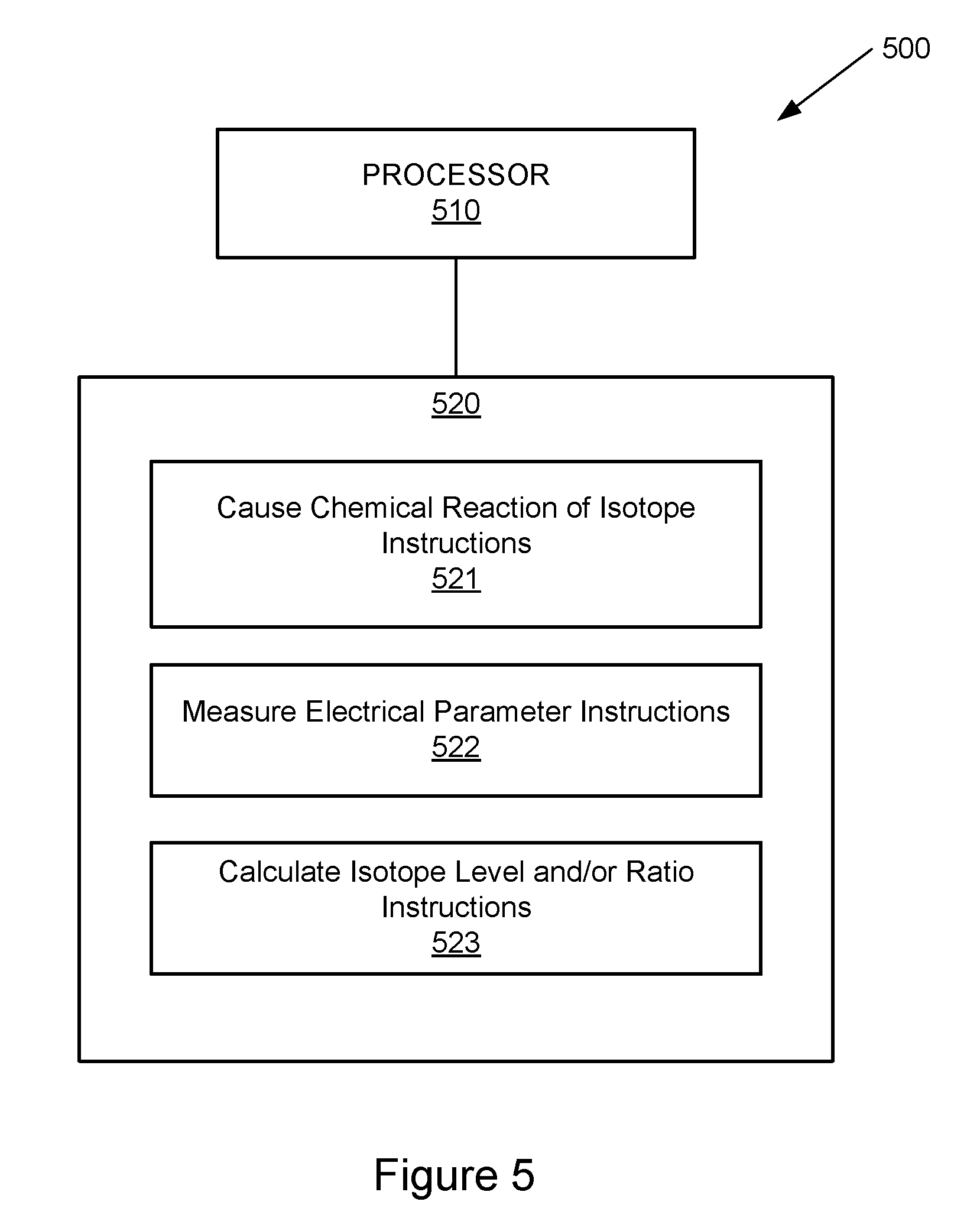
[0032] Referring now to FIG. 5, a block diagram of an example system is illustrated with a non-transitory computer-readable storage medium including instructions executable by a processor. The system 500 includes a processor 510 and a non-transitory computer-readable storage medium 520. The computer-readable storage medium 520 includes example instructions 521-523 executable by the processor 510 to perform various functionalities described herein. In various examples, the non-transitory computer-readable storage medium 520 may be any of a variety of storage devices including, but not limited to, a random access memory (RAM) a dynamic RAM (DRAM), static RAM (SRAM), flash memory, read-only memory (ROM), programmable ROM (PROM), electrically erasable PROM (EEPROM), or the like. In various examples, the processor 510 may be a general purpose processor, special purpose logic, or the like.
[0033] The example instructions include causing chemical reaction of isotope instructions 521. As described above with reference to FIG. 1, the reaction control portion 120 may cause a chemical reaction (e.g., oxidation) related to a material containing at least one isotope.
[0034] The example instructions further include measuring electrical parameter instructions 522. As described above with reference to FIG. 1, the electrical parameter portion 130 of the example device 100 may measure an electrical parameter (e.g., resistance) associated with the isotope portion 110 or the material having at least one isotope.
[0035] The example instructions further include calculating an isotopic material level and/or ratio instructions. As described above with reference to FIG. 1, in some examples, the isotope portion 110 includes a material with a single isotope. As the reaction control portion 120 causes or reverses a chemical reaction such as, for example, oxidation of the material with the single isotope, the level of isotope in the material may increase or decrease, depending on the direction of the chemical reaction. In turn, this may increase or reduce the resistance value of the material. Thus, the electrical parameter portion 130 may measure a change in resistance, and the change in resistance may be associated with a change in the level of the material containing the isotope.
[0036] In other examples of the example system 100 of FIG. 1, the isotope portion 110 includes materials with at least two different isotopes. As the reaction control portion 120 causes or reverses a chemical reaction of each material such as, for example, oxidation of the materials, the ratio of two materials containing different isotopes may increase or decrease in accordance with KIE described above, depending on the direction of the chemical reaction. In turn, this may increase or reduce the resistance value of the material. Again, the electrical parameter portion 130 may measure a change in resistance, and the change in resistance may be associated with a change in the isotope ratio.
[0037] The foregoing description of various examples has been presented for purposes of illustration and description. The foregoing description is not intended to be exhaustive or limiting to the examples disclosed, and modifications and variations are possible in light of the above teachings or may be acquired from practice of various examples. The examples discussed herein were chosen and described in order to explain the principles and the nature of various examples of the present disclosure and its practical application to enable one skilled in the art to utilize the present disclosure in various examples and with various modifications as are suited to the particular use contemplated. The features of the examples described herein may be combined in all possible combinations of methods, apparatus, modules, systems, and computer program products.
[0038] It is also noted herein that while the above describes examples, these descriptions should not be viewed in a limiting sense. Rather, there are several variations and modifications which may be made without departing from the scope as defined in the appended claims.
* * * * *
D00000
D00001
D00002
D00003
D00004
XML
uspto.report is an independent third-party trademark research tool that is not affiliated, endorsed, or sponsored by the United States Patent and Trademark Office (USPTO) or any other governmental organization. The information provided by uspto.report is based on publicly available data at the time of writing and is intended for informational purposes only.
While we strive to provide accurate and up-to-date information, we do not guarantee the accuracy, completeness, reliability, or suitability of the information displayed on this site. The use of this site is at your own risk. Any reliance you place on such information is therefore strictly at your own risk.
All official trademark data, including owner information, should be verified by visiting the official USPTO website at www.uspto.gov. This site is not intended to replace professional legal advice and should not be used as a substitute for consulting with a legal professional who is knowledgeable about trademark law.