Collection Of Suspended Cells Using A Transferable Membrane
Shao; Hung-Jen
U.S. patent application number 16/124092 was filed with the patent office on 2019-08-08 for collection of suspended cells using a transferable membrane. The applicant listed for this patent is CellMax, Ltd.. Invention is credited to Hung-Jen Shao.
| Application Number | 20190242796 16/124092 |
| Document ID | / |
| Family ID | 58387673 |
| Filed Date | 2019-08-08 |


View All Diagrams
| United States Patent Application | 20190242796 |
| Kind Code | A1 |
| Shao; Hung-Jen | August 8, 2019 |
COLLECTION OF SUSPENDED CELLS USING A TRANSFERABLE MEMBRANE
Abstract
Devices, methods, and kits directed towards collecting and preparing cells using a separable sample collection layer may be configured to collect or treat cells from a liquid sample with mechanisms for easy transfer of the cells prior to analysis or imaging. The separable sample collection layer may comprise a porous membrane that cells may be collected on, and one or more support layers comprising tape with one or more adhesive coatings and release liner. The devices, methods and kits may be configured with support layers comprising cutouts that form vertically or horizontally oriented microchannels for efficiently removing undesirable liquid. Following collection and/or treatment, cells collected onto the porous membrane may be adhered to another surface for further processing or analysis.
| Inventors: | Shao; Hung-Jen; (Taipei, TW) | ||||||||||
| Applicant: |
|
||||||||||
|---|---|---|---|---|---|---|---|---|---|---|---|
| Family ID: | 58387673 | ||||||||||
| Appl. No.: | 16/124092 | ||||||||||
| Filed: | September 6, 2018 |
Related U.S. Patent Documents
| Application Number | Filing Date | Patent Number | ||
|---|---|---|---|---|
| 15072287 | Mar 16, 2016 | 10107726 | ||
| 16124092 | ||||
| Current U.S. Class: | 1/1 |
| Current CPC Class: | C12M 33/14 20130101; B01D 63/081 20130101; G01N 1/312 20130101; B01L 3/502761 20130101; B01L 2300/0887 20130101; B01L 2300/0816 20130101; C12M 47/02 20130101; B01L 3/502753 20130101; B01L 2300/048 20130101; B01D 63/088 20130101; G01N 1/30 20130101; B01L 2300/126 20130101; B01L 2300/0681 20130101 |
| International Class: | G01N 1/31 20060101 G01N001/31; C12M 1/00 20060101 C12M001/00; B01D 63/08 20060101 B01D063/08; G01N 1/30 20060101 G01N001/30; B01L 3/00 20060101 B01L003/00; C12M 1/26 20060101 C12M001/26 |
Claims
1.-18. (canceled)
19. A method of collecting and preparing cells comprising: (a) applying a biological sample comprising cells to a separable sample collection layer comprising a support layer and a porous membrane disposed against a solid support layer, wherein the cells are applied onto the porous membrane of the separable sample collection layer; (b) perfusing one or more liquid solutions through the porous membrane of the separable sample collection layer; (c) removing the separable sample collection layer from a supporting surface; and (d) transferring the separable sample collection layer to another surface.
20. The method of claim 19, wherein the another surface is a glass slide.
21. The method of claim 19, wherein the support layer comprises double coated tape.
22. The method of claim 19, wherein the removing the separable sample collection layer comprises separating the separable sample collection layer from the supporting surface
23. The method of claim 19, wherein the method further comprises adhering the sample collection layer to another surface.
24. The method of claim 19, wherein the transferring comprises transferring the sample collection layer such that a sample collected by the separable sample layer is between the porous membrane and the another surface
25. The method of claim 19, wherein prior to perfusing, the one or more liquid solutions comprises a cells, a foam, a lipid, or both.
26. The method of claim 19, wherein prior to perfusing, the one or more liquid solutions comprise circulating tumor cells (CTCs).
27. The method of claim 19, wherein the perfused liquid comprises an antibody, a buffer, a cell stain, a cell staining reagent, a reagent for fixing cells, or a surfactant.
28. The method of claim 19, wherein the method further comprises processing or analyzing a sample collected on the separable sample collection layer after transferring the separable sample collection layer to another surface.
31. The method of claim 19, wherein the method further comprises directing a liquid using one or more microchannels or cutouts, wherein the liquid comprises at least one of the perfused liquid solutions or a liquid fraction of the sample.
32. The method of claim 31, wherein the directing occurs horizontally within layers.
33. The method of claim 31, wherein the directing occurs vertically between layers.
34. The method of claim 31, wherein the directing is assisted using gravity.
35. The method of claim 31, wherein the directing is assisted using pressure or a vacuum.
36. The method of claim 19, further comprising prior to c), removing a liquid fraction of the sample.
37. The method of claim 19, wherein in c) the separable sample collection layer comprise one or more cells of the cells that are applied onto the porous membrane of the separable sample collection layer.
38. The method of claim 19, wherein the support layer comprises an adhesive surface and a release liner.
39. The method of claim 21, wherein in a), the double coated tape is adhered to at least one of the porous membrane, a release liner, or the solid support layer.
40. The method of claim 38, wherein in a), the adhesive surface is adhered to the release liner
41. The method of claim 40, wherein the removing comprises separating the adhesive surface from the release liner.
42. The method of claim 40, wherein the method further comprises adhering the adhesive surface to the another surface.
43. The method of claim 19, wherein the supporting surface comprises release paper.
44. The method of claim 43, wherein the separable sample collection layer comprises an adhesive adhered to the release paper, and the removing comprises separating the adhesive from the release paper.
45. The method of claim 19, wherein removing comprises peeling the separable sample collection layer from the supporting surface using mechanical force.
46. The method of claim 45, wherein the removing is performed such that cells in the biological sample remain viable.
47. The method of claim 19, wherein the method further comprises fixing one or more cells of the biological sample with paraformaldehyde.
48. The method of claim 27, wherein the perfused liquid interacts with cells of the biological sample such that the cells are fixed, stained, washed, bound to antibodies, or a combination thereof.
49. The method of claim 28, wherein the processing or analyzing comprises imaging
Description
BACKGROUND OF THE INVENTION
[0001] Separating, preparing, and treating biological cells suspended in a liquid sample solution onto a surface or substrate can be a non-trivial and critical step in a variety of applications including sample diagnostic procedures and cell imaging. A key challenge involves collecting biological cells suspended in solution onto a surface such that the cells may be easily treated and then quickly transferred to another surface for imaging or analysis. The health of cells suspended in a sample may also be important, therefore it may be advantage to limit cell disruption during sample transfer and collection. Mechanical forces applied to the cells must be gentle so as not to disrupt the cell structure or negatively impact cell health yet strong enough to manipulate the cells effectively. To maintain the health of cells and facilitate efficient preparation of liquid samples, devices and methods may be constructed that enable cells to be collected and treated onto a device and then removed from the device for transfer or adherence to another substrate for analysis.
SUMMARY OF THE INVENTION
[0002] The disclosed device may comprise a device for collecting cells of interest. The device may comprise a solid support coupled to a first support layer; and a separable sample collection layer comprising a porous membrane coupled to a second support layer. In some instances the porous membrane may be positioned between the first support layer and the second support layer. In further embodiments, the first support layer and the second support layer may maintain the porous membrane in a static position. Additional embodiments may comprise a device with a solid support, a first support layer, and a second support layer in fluid communication through at least one microchannel.
[0003] Support layers may comprise one or more components. For example, the support layer may comprise any combination of a release liner and adhesive tape, for example double coated tape. The release liner may comprise a backing or backing with adhesive and a release liner. The release liner may be comprised of paper, plastic, or other solid backing, and it may be coated with a low surface forces coating. In some embodiments the support layer may comprise a polyethylene terephthalate (PET) film coated with acrylic adhesive, and a release liner.
[0004] The solid support of the device may comprise a transparent solid material, for example acrylic plastic or glass, and it may be constructed to allow for drilling of microchannels. In some instances the microchannel may be circular with a diameter of approximately 10 mm.
[0005] Microchannels may be used to connect the solid support, the first support layer, and the second support layer with cutouts that form a channel, in some instances the channel may be occluded by a porous membrane. Porous membrane may have pore sizes up to 10 microns in diameter. The average pore size of the porous membrane may be 2-5 microns in diameter. In further embodiments, the average pore size of the porous membrane may be less than 2 microns in diameter. The porous membrane may comprise polycarbonate. The porous membrane may also be circular with a 25 mm diameter. In some embodiments, the porous membrane may be in fluid communication with the solid support and one or more support layers.
[0006] The device may comprise one or more microchannels in fluid communication with the solid support and one or more of the support layers. In some embodiments the device may comprise a horizontal microchannel cut into the first support layer, the horizontal microchannel may establish fluid communication between two microchannels positioned vertically to the horizontal microchannel. In some embodiments, a first vertical microchannel may be disposed through the solid support and in fluid communication with a horizontal microchannel disposed within the first support layer. Where vertical orientation is defined as the direction that covers the width or thinner segment of the device, and horizontal orientation is defined as the direction that covers the length, or longest segment of the device. Further embodiments may comprise a second vertical microchannel disposed through the second support layer and in fluid communication with the horizontal microchannel of the first support layer. In even further embodiments, the first and the second vertical microchannels may be oriented parallel to each other such that fluid communication occurs through the horizontal microchannel of the first support layer.
[0007] In further embodiments, the device may be disposed against an absorbent pad. In some embodiments, the device may be disposed against an absorbent pad, and the absorbent pad may be in fluid communication with one or more microchannels in the device. In some instances, the absorbent pad may be on a first side of the solid support structure, where the porous membrane is on the second side of the solid support structure. In other embodiments, the separable sample collection layer may be disposed against an absorbent pad.
[0008] A method for manufacturing a device for collecting cells may comprise steps for layering a porous membrane between one or more support layers onto a solid support structure; cutting one or more microchannels into the one or more of the layers to enable fluid communication through the device; and arranging the porous membrane and one or more support layers such that the porous membrane can be separated from a solid support structure and transferred to a separate surface for additional processing. In some instances the support structure and the one or more support layers may be in fluid communication through the porous membrane. The support layer may comprise double coated tape with release liner such that tape comprises a carrier with adhesive on both sides and a separable release liner. In further instance the first and the second separable layers may be arranged such that the porous membrane can be selectively removed and adhered to one or more new surfaces for additional processing or analysis. The support layer may comprise a polyethylene terephthalate (PET) film coated with acrylic adhesive and a release liner. The support layer may have a porous membrane has pores up to 10 microns in diameter, adhered to it. A porous membrane may be configured to collect cells larger than a particular size, using pores of 2-5 microns in diameter. Alternately the porous membrane may have a fixed pore size. The porous membrane may be comprised of polycarbonate, and it may be circular with a 25 mm diameter.
[0009] A method of collecting and preparing cells may comprise applying biological sample to a separable sample collection layer. The sample collection layer may comprise a support layer and a porous membrane. In some instances the sample collection layer may be disposed against a solid support layer, and cells may be applied onto the porous membrane of the separable sample collection layer. A method for collecting and preparing cells may comprise perfusing one or more liquid solutions through the porous membrane of a separable sample collection layer. Further steps of the method may comprise removing the separable sample collection layer from a supporting surface; and transferring the separable sample collection layer to another surface for further processing or analysis. In some instance the sample collection layer may be transferred to a glass slide for imaging. In further embodiments the support layer may be a piece of double coated tape with release liner. Removing the sample collection layer may comprise separating the sample collection layer from the supporting surface. Transferring the sample collection layer may comprise adhering the sample collection layer to another surface. The sample collection layer may be oriented with the sample collected on the filter facing down, between the porous membrane and another surface.
[0010] Sample may comprise one or more of the following: cells, foam, liquid, or lipid. In some embodiments the perfused liquid solution may comprise cells, including CTCs. Liquid may comprise antibodies, buffer, cell stain, cell staining reagent, reagents for fixing cells including paraformaldehyde, or surfactants, any of which may be applied to the sample using the device. Sample may accumulate onto a separable sample collection layer, and the separable sample collection layer may be transferred to a slide for imaging.
[0011] In some instances a kit may be created for collecting and preparing cells. The kit may comprise one or more units of double coated tape with release liner; one or more pieces of pre-cut porous membrane; and one or more solid support structures. The kit may be configured so that users may receive the kit and assemble a device for collecting and treating a liquid sample comprising cells. In some embodiments a kit may comprise an instruction manual describing steps for device assembly and cell preparation. The porous membrane provided in the kit, may be pre-cut into the shape of a truncated circle. The kit may further comprise double coated tape with release liner pre-cut into at least two different sizes. Components of the kit may be configured for assembly and application in a broad range of cell filtering, treatment and imaging applications.
INCORPORATION BY REFERENCE
[0012] All publications, patents, and patent applications mentioned in this specification are herein incorporated by reference to the same extent as if each individual publication, patent, or patent application was specifically and individually indicated to be incorporated by reference.
BRIEF DESCRIPTION OF THE DRAWINGS
[0013] FIG. 1 shows an expanded view of the sample collection device.
[0014] FIG. 2A-2D illustrate the components connected to form a removable layers and fixed component with a microchannel for transferring sample into and directly out of the device.
[0015] FIGS. 3A-3B illustrate flow of sample directly through the device, and FIG. 3C illustrates separation of the separable sample collection layer and porous membrane from the fixed component in a device configured for transferring sample directly out of the device.
[0016] FIGS. 4A-4B illustrate that the solid support can vary in thickness.
[0017] FIGS. 5A-5D illustrate components connected to form a separable sample collection layer and a fixed component with cutouts that form microchannels for moving sample through the device.
[0018] FIG. 6 illustrates an expanded view of a non-limiting embodiment of a sample collection device with cutouts that form microchannels for moving sample through the device, without an absorbent pad and without sample moving directly out of the device.
[0019] FIG. 7 illustrates an expanded view of another non-limiting embodiment of a sample collection device with cutouts that form microchannels for moving sample through the device with some component of the sample moving directly out of the device.
[0020] FIG. 8 illustrates an expanded view of another non-limiting embodiment of a sample collection device with cutouts that form multiple horizontal microchannels for moving sample through the device.
[0021] FIGS. 9A-9D illustrate exemplary dimensions of sample collection device with cutouts that form microchannels for moving sample through the device.
[0022] FIG. 10A-10D show connected components that form a separable sample collection layer and a fixed component, in a sample collection device with cutouts that form microchannels for moving sample through the device.
[0023] FIG. 11 shows microchannels in the top and bottom of the device.
[0024] FIG. 12 shows different steps or configurations for using the device to prepare a sample.
[0025] FIG. 13 shows steps for using the device to prepare components for preparing sample for immunofluorescence imaging.
[0026] FIG. 14 shows steps for using the device to defoam and prepare sample for immunofluorescence.
[0027] The novel features of the invention are set forth with particularity in the appended claims. A better understanding of the features and advantages of the present invention will be obtained by reference to the following detailed description that sets forth illustrative embodiments, in which the principles of the invention are utilized, and the accompanying drawings of which:
DETAILED DESCRIPTION OF THE INVENTION
[0028] The present application discloses devices, systems, and methods for collecting one or more suspended components of a liquid sample (e.g. biological cells) onto a porous membrane. The disclosed devices, systems and methods may be configured for cleaning, treating and/or easily transferring selected components of a liquid sample, for example a liquid sample comprising biological cells. Devices or systems may comprise a fixed component comprising a solid support to which a first support layer is affixed. A separable sample collection layer comprising a porous membrane affixed to a second support layer, may be removably affixed to the first support layer. Liquid sample comprised suspended cells may be applied to the porous membrane through cutouts in the first support layer and second support layer, allowing the cells to collect on the porous membrane and separate from the liquid fraction which may move through the device. The sample may be treated with liquid washes, or subjected to additional treatment steps or protocols. Once collection and/or treatment is complete, the separable sample collection layer may be peeled away from the fixed component of the device and adhered to one or more other surfaces for further treatment, fixing, or analysis.
[0029] In some embodiments the first support layer may comprise a layer with one or more microchannels or cutouts configured to direct the liquid fraction of the sample. In further embodiments the orientation of the microchannels and flow through the microchannels may be directed vertically through one or more layers of the device, horizontally within one layer of the device, or in further embodiments the device may comprise elements of vertical and horizontal flow. In some embodiments flow of the liquid fraction of the sample may be unassisted or directed by gravity, for example in a device that relies on vertical flow, or in a device that has a horizontal microchannel connected by one or more vertical microchannels, and in other embodiments flow of the liquid fraction of the sample may be assisted by pressure or vacuum. In some instances flow of the liquid fraction of a sample may be broken into one or more separated flows of the liquid fraction. Separated flows may move in opposing directions and/or rely on different mechanisms for removing the liquid, for example gravity, pressure, and suction. In some instanced the device may utilize one or more vertically oriented microchannels or wells designed to sustain fluid contact within one or more microchannels within a device, the channels may be configured to integrate with one or more other devices that may use pressure or suction to remove the liquid fraction of the sample and/or prepare or treat the sample by flowing washing buffers, reagents, or other liquid treatments through the device. Following separation or treatment of a sample, the device may be configured to facilitate removal of the sample through separation of the separable sample collection layer from the fixed component of the device. The separable sample collection layer containing the sample may be adhered to one or more new surfaces for subsequent treatment or analysis.
[0030] The separable sample collection layer may comprise a support layer for removably affixing the membrane to the first support layer. In some embodiments the first support layer may be a release liner, and the separable sample collection layer may be removably affixed to the first support layer using tape. The separable sample collection layer may be configured such that it comprises an adhesive surface that is exposed when the separable sample collection layer is selectively peeled off of a fixed component of the device and adhered to another surface. In some instances the separable sample collection layer may be adhered to another surface using the adhesive exposed by separation of the sample collection layer from the first support layer. In other instances the separable sample collection layer may be adhered to another surface through an adhesive that was not exposed by removal from the first support layer.
[0031] The second support layer of the separable sample collection layer may comprise a piece of double coated tape, wherein one adhesive coated side of the double coated tape is adhered to the porous membrane and disposed facing the anti-stick or low surface forces coating of release liner comprising the first support layer, and the other side of the double coated tape is disposed facing an anti-stick or low surface forces coating of release liner that is part of the second support. In some instances the alternate surface may be the face or side of the support layer that the porous membrane is not directly adhered onto.
[0032] In some embodiments the separable sample collection layer may comprise a porous membrane coupled to a second support layer comprising double coated tape and release liner. One side of the double coated tape may be adhered to a piece of release liner, and the other side of the double coated tape may be used to affix a piece of porous membrane onto a fixed component of the device. The fixed component of the device may comprise a first support layer, and a solid support. The first support layer may comprise a piece of release liner directly adhered to the solid support, such that the porous membrane is disposed between adhesive from the second support layer and the release coating side of the release liner.
[0033] Vertical or horizontal microchannels may be formed by one or more cutouts or microchannels cut into one or more supports. Vertical microchannels may be formed by cutouts through one or more layers above and/or below each ajoining layer, and horizontal microchannels may be formed by cutouts in a single horizontal layer, creating a microchannel between the layers that has the depth of the thickness of the support and no cutout in the corresponding region in the above or below adjoining layer. Horizontal microchannels may be formed by cutouts in a layer that is sandwiched between other layers, for example the first support layer, such that fluid can flow vertically into the device and horizontally between the layers of the device. In some instances one or more additional vertical microchannels may be disposed from the horizontal microchannel, such that sample could flow vertically into the device, then through one or more horizontal microchannels and then out of the device through one or more vertically oriented microchannels.
[0034] In some instances cutouts of similar or equivalent size and shape may be cut into in one or more of the supports to form a vertical microchannel that may be disposed partially or entirely through the device. For example, a vertical microchannel may be formed by cutouts in the first and second support, the cutouts may be occluded by the porous membrane which may be disposed between the cutouts of the supports. The porous membrane may be exposed between a first support and a second support, and function like a sieve that collects solid components of a sample (e.g. cells) as liquid sample flows through the vertical microchannel formed by cutouts in the support layers. In some embodiments the region formed by cutouts in the supports may be referred to as the sample application zone. The sample application zone may comprise a microchannel formed by cutouts in the first and second supports may be occluded by the porous membrane, in these instances the membrane may be sandwiched between the first and second supports, forming a channel with depth equivalent to the additive thickness of the first support, the second support, and the porous membrane.
[0035] In some configurations, one or more microchannels may be formed by cutouts created within a single support layer disposed between one or more additional vertically oriented microchannels. In further configurations still, the device may be configured with support components comprising release liner and adhesive, such that the separable sample collection layer may be separated from the fixed component using adhesive that has been separated from release liner. In further configurations still, the separable sample collection layer may be configured such that the adhesive exposed by removal of the separable sample collection layer may be used to adhere the separable sample collection layer to another surface. In other instances the second support layer may comprise a release liner coupled to an adhesive layer, on the side of the second support layer disposed facing away from the fixed component. In some instances the release liner component of the second support layer may be removed to expose an adhesive surface that may be used to adhere the sample to a new surface, this adhesive surface may be used instead of or in concert with other adhesive surfaces on the second support layer, for example the adhesive surface exposed by separation of the separable sample collection layer from the first support layer of the fixed component. In embodiments where the second support layer comprises two adhesive surfaces, one or both of the adhesive surfaces may be used to attach the sample to a new surface. In some instances both adhesive surfaces may be used to assemble the sample collection layer between two new surfaces, for example between a glass slide and a coverslip.
[0036] In some instances the separable sample collection layer may be separated from the fixed component, such that it can be adhered to another surface. The separable sample collection layer may be comprised of multiple components, including a second support layer and a porous membrane. The second support may comprise release liner and double coated tape. Release liner may comprise a strip of backing material, for example paper, that is coated on one or both sides with a low surface forces material coating. The coating may be shiny and smooth, and configured such that adhesive can be easily peeked away from the surface. Support layers may be comprised of tape. Tape may comprise a strip of polymer backing material coated on one or both sides with adhesive. The second support may comprise a piece of double coated tape with one side of the double coated tape adhered to the low surface forces coating of the release liner and the other side adhered to some or all of the surface of a porous membrane, which may be smaller than the release liner and thus leave some of tape adhesive surface exposed beyond the perimeter of the porous membrane. In some embodiments the porous membrane may be disposed between the release coating of the first support and the adhesive coating of the second support. In further embodiments, the first support may have a larger size than the second support, and the porous membrane may have a smaller size than both the first support and the second support. In some embodiments the porous membrane may be adhered to the adhesive of the second support, such that part of the adhesive is covered by the membrane, and remaining adhesive surface may be adhered to a low surface forces coating of the first support. In such a configuration the fixed component may comprise release liner with the release coating disposed facing the porous membrane and the adhesive of the second support layer, such that the porous membrane is sandwiched between the second support layer and the fixed component. In some instances the supports and the membrane may be configured such that the separable sample collection layer may be easily removed (e.g. gripping the sample collection layer using tweezers or forceps and then peeling off the membrane) from the fixed component during separable sample collection layer to another surface with the sample component collected on the porous membrane exposed to the air or exposed to the new surface. In some instances, the new surface may be a glass coverslip, in which case the adhesive surface that was peeled away from the fixed component may be transferred and adhered to another surface. In other methods where the sample is adhered to another substrate with the sample components collected on the porous membrane oriented face up and exposed, release liner attached to the side opposite to the side the porous membrane is adhered may be removed from the separable sample collection layer to expose the adhesive surface to affix the release layer to the new surface.
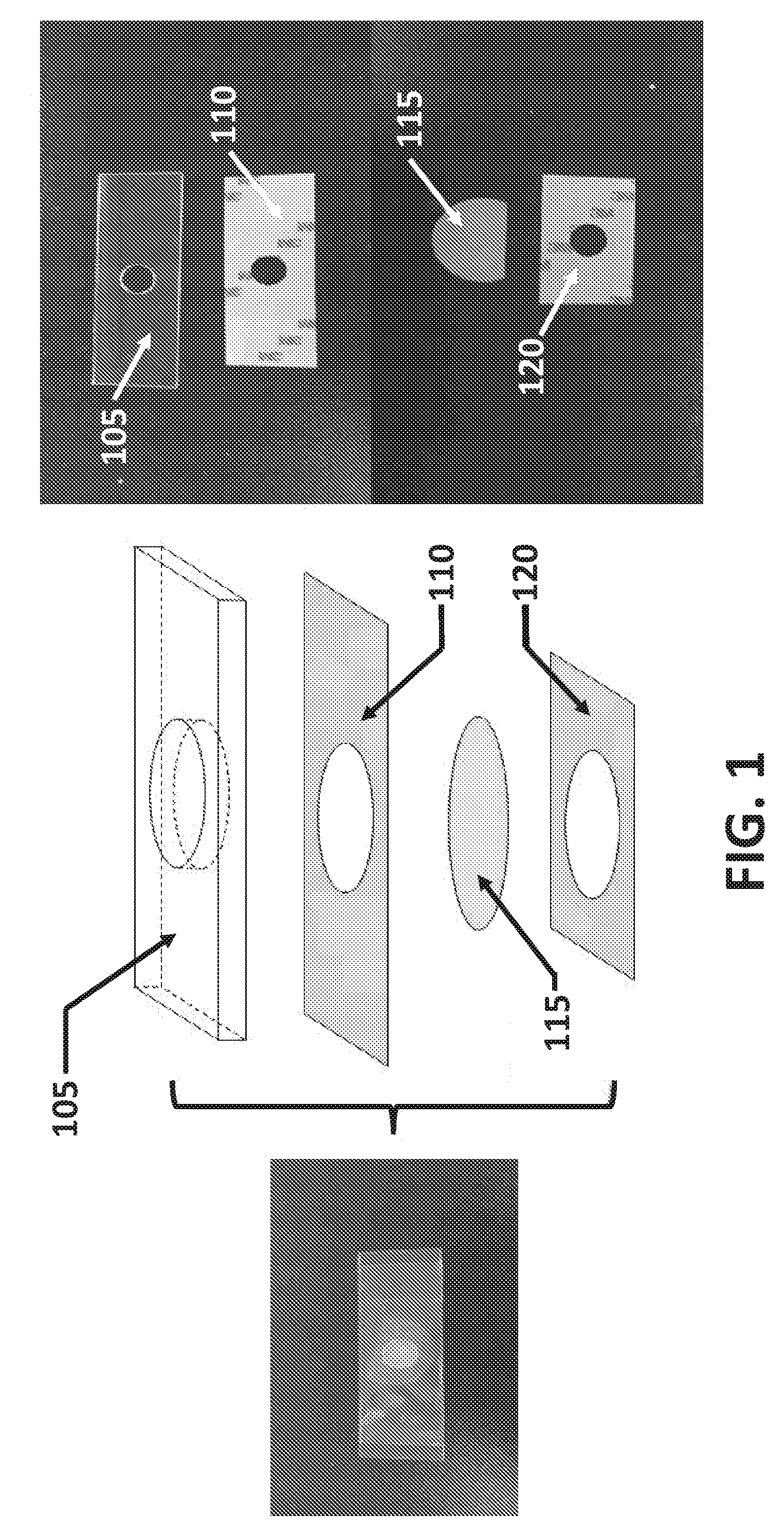
[0037] FIG. 1 illustrates a non-limiting embodiment of the assembled device. The device may be constructed from multiple layers. In some embodiments, the device may comprise a number of supports including a solid support (105), a first support layer (110), and a second support layer (120). A porous membrane (115), for collecting desirable components of the sample may be disposed between the first support layer and the second support layer. In some instances the porous membrane (115) may be disposed between the first support layer and the second support layer such that the porous membrane may be easily separated from the solid support and transferred to another surface.
[0038] The device may comprise one or more solid supports (105) with defined shape and compositions. In some instances the defined shape may be a 3 dimensional shape, for example a rectangular prism, a cylindrical, or a square prism. Further embodiments may comprise one or more cutouts. For example, as shown in FIG. 1, the solid support (105) may form a rectangular prism with a circular cutout. The one or more cutouts may also have a defined 3 dimensional shape; for example, in some instances a 3 dimensional shape may include cylindrical, conical, and pyramidal. The cutout may be positioned anywhere within the solid support, for example as shown in FIG. 1, the circular cutout is spaced equally in the center of the solid support with equal spacing between the short sides of the solid support (105).
[0039] A solid support may be constructed from any materials. Materials may consist of a single material, or may comprise a mixture of more than one material. The materials used to form the solid support may be transparent or opaque. In some embodiments the solid substrate may be constructed from one or more types of plastics including thermoplastics, polymers, and glass. Example materials may include acrylic or poly(methyl methacrylate) (PMMA), acetonitrile butadiene styrene (ABS), nylon, polylactic acid (PLA), polybenzimidazole, polycarbonate, polyether sulfone, polyetherether ketone, polyetherimide, polyethylene, polyphenylene oxide, polyphenylene sulfide, polypropylene, polystyrene, polyvinyl chloride, and teflon. The solid substrate may be constructed using a variety of methods including injection molding, carving, machining, casting, extrusion, or any other commonly accepted approaches for producing a solid material.
[0040] The device may comprise a fixed component comprised of a solid support and a first support layer, and a separable sample collection layer comprising a second support layer and a porous membrane. A first support layer or second support layer may comprise any combination of: backing, release agent and adhesive. Backing may comprise any solid surface onto which an adhesive or release agent is applied. Adhesives may comprise any material, surface, or layer comprising a high surface energy coating that promotes adherence between two surfaces. Release agents, release liner, and/or release coating may refer to any low surface energy coating that promotes release or separation between two surfaces. In some embodiments the support may comprise one or more layers of commercially available adhesive, release liner including industrial release liner, release agent, releasable or non-stick films, protective film, polyester film, casting paper, or plastic film. Backing in the support may comprise paper, polymer, plastic film, cloth, metal foil, or other similar materials. Paper backing may include super calandered kraft paper (SCK), Glassine which may include a layer of polyvinyl alcohol (PVOH), clay coated kraft paper (CCK), machine finished kraft paper (MFK), and machine glazed paper (MG). Plastic films or plastic substrate may include polyethylene terephthalate (PET) including biaxially-oriented PET, polypropylene including biaxially-oriented polypropylene, polypropylene plastic resins, and polyolefins including high-density and low-density polyolefins. The surface may comprise backing with of one or more high surface energy coating for example an adhesive or mastic, and one or more low surface energy coatings or release coating. Adhesives may comprise natural adhesives, semi-synthetic adhesives, and synthetic adhesives. Natural adhesives may comprise any single of starch, dextrin, gelatin, asphalt, bitumin, natural rubber, resins, shellac. Semi-synthetic adhesive may be cellulosic polymers, including cellulose nitrate, cellulose acetate butyrate, methyl cellulose, and ethyl cellulose. Synthetic adhesives may comprise vinyls, acrylics, reactive acrylic bases, synthetic rubbers, aldehyde condensation resins, epoxide resins, amine base resins, polyester resin, polyolefin polymers, soluble silicates, phosphate cements, and hydraulic cements. Additional examples of adhesives include polyvinyl acetate, polyvinyl alcohol, polyvinyl polymers from the poly acrylic acid, epoxies, polyurethanes, polyimides. Adhesive may be pressure sensitive, wherein the support layer will stick to a surface with the application of pressure without the need for a solvent or heat. The support layer may be further configured with one or more cutouts of a variety of shapes and patterns (i.e. circular, square, rectangular, star-shaped, swirls, concentric circles). The support layer may comprise 3M 8018PT Double Coated Acrylic Adhesive PET Tape.
[0041] A device may be comprised of a first support layer configured to be permanently affixed to the solid support, and a second support layer configured to be removably affixed to the first support layer and the fixed component of the device formed by the first support layer and the solid support. To facilitate separation between the support layers, the first support layer and/or second support layer may comprise one or more components including an adhesive surface for affixing the support to the solid support or to the porous membrane, and one or more pieces of release liner for easy removal or separation of one or more layers, supports, or components of the device. In some embodiments the second support layer may have surface area less than or equal to the surface area of the first support layer. In other embodiments, the second support layer may have surface area greater than or equal to the first support layer.
[0042] The porous membrane may be sandwiched between one or more of the supports, such that cutouts in the supports form a microchannel with a sample application zone, where the sample can be applied directly to the porous membrane. Sample may be dripped onto the sample application zone through the cutout, sample components larger than the porous membrane pore size are caught by the porous membrane, and liquid and/or other components smaller than the sample pass through a porous membrane. The porous membrane may be held between one or more supports with one or more layers of adhesive, backing, and/or release coatings.
[0043] The porous membrane may comprise one or more porous materials with characterized material properties, composition, and pore size. The porous membrane may be strong, wherein strength is defined as the amount of force to break the porous membrane wherein strength is measured as burst from longitudinal force and/or tensile strength from lateral forces. The porous membrane may be chemically or biologically clean, such that the porous membranes are cast and handle in clean rooms under ambient conditions. The porous membranes may have high porosity such that the gas or liquid can readily flow through the porous membrane, with the porous membrane providing high surface area for adsorption. Materials may include microporous plastic, polymer, or paper filters. Material may include supported or unsupported surfaces with polymers including cellulose, mixed cellulose esters, cellulose acetate, polycarbonate, polytetrafluoroethylene (PTFE) including hydrophobic PTFE and hydrophilic PTFE, and nylon. The porous membrane may comprise Millipore porous membrane number TTTP02500. Porous membranes may be produced from a variety of processes including casting, stretching and etching. The porous membrane may have fixed or variable pore size. The pore size of the materials porous membrane may be configured to retain particles greater than or equal to 150 microns, 100 microns, 50 microns, 30 microns, 20 microns, 10 microns, 5 microns, 4 microns, 3 microns, 2 microns or 1 micron. The porous membrane may have be uniformly thin, with a width of less than or equal to, 1,000 microns, 800 microns, 600 microns, 500 microns, 400 microns, 300 microns, 200 microns, 150 microns, 50 microns, 30 microns, 20 microns, or 10 microns. The porous membrane may be coated in agents that reduce sticking for example polymers, proteins or other agents or combinations of agents or components. The porous membrane may be thermostable, such that the porous membranes can be sterilized using heat or autoclaving, under temperatures up to 140.degree. C., 160.degree. C., 180.degree. C., 220.degree. C., 240.degree. C., 260.degree. C., 280.degree. C., 300.degree. C., or 320.degree. C. with minimal shrinking or effect to the shape.
[0044] As shown in FIG. 2, a device for example the device depicted in FIG. 1, may be separated into two separable layers; a fixed component (225) and a separable sample collection layer (230) that may be separated from the fixed component along with sample components collected on the porous membrane. The fixed component may comprise one or more layers, which may include a fixed component (225) comprising a solid support (205) and a first support layer (210). In some embodiments the fixed component (225), as depicted in FIGS. 2A and 2B, may comprise a solid support (205) comprising PMMA adhered to one side of a first support layer (210) comprising 3M 8018PT Double Coated Acrylic Adhesive PET Tape. The first support layer (210) may comprise a solid backing material with an adhesive surface on one side for adhering the first support layer to the solid support (205), and a release coating or release liner on the other side configured such that a separable sample collection layer (230) may attach to the device and be configured such that it may easily be removed. The separable sample collection layer (230) may also be comprised of one or more components. For example, in some embodiments as depicted in FIG. 2C and FIG. 2D, the separable sample collection layer (230) may be formed from porous membrane (215) and a second support layer (220). In some embodiments the separable sample collection layer (230), as depicted in FIGS. 2C and 2D, may comprise a porous membrane (215) comprised of millipore TTP02500, adhered to one side of a removable (220) support comprising 3M 8018PT Double Coated Acrylic Adhesive PET Tape. The second support layer (220) may comprise a solid backing material with an adhesive surface that adheres to release coating or release liner of the first support layer (210), and the other side of the backing material. In some instances, the side of the release support (220) backing that faces away from the device may comprise an additional adhesive layer, release coating, release liner or any combination thereof. In some embodiments the separable sample collection layer (230) may be affixed to the top of the fixed component (225).
[0045] In some instances it may be desirable to separate one or more larger or solid sample components from a liquid or partially liquid sample. In some instances, the device may be used to collect cells that have been collected into a liquid solution that comprises the desired cells and other elements or components that are undesirable for example bubbles, foam, solvent, solutions, or smaller solid components including particulate matter or antibodies that are not useful. In some instances the desirable component may comprise cells that have been selectively removed from a sample, for example a whole blood sample, in an earlier procedure. In such examples it may be desirable to selectively separate cells from a solution containing foam, bubbles, solvent, solutions or other components that may be undesirable in subsequent procedures. It may be desirable to use a device that can collect the cells and facilitate cleaning of collected components, as well as transfer of the desirable components to further steps. In some instances it may be desirable to use a device to remove foam, bubbles, solvent, solutions and/or other smaller components, without significantly disrupting the cells during transfer to subsequent steps.
[0046] A device for cleaning, treating, separating, and/or transferring large desirable sample components, for example as described in FIGS. 3A-3B, the device may be configured to collect components from an initial sample flow (Flow 1), from which the desirable components are removed, this collection may result in a second sample flow (Flow 2) which may be removed from the device using suction or other means. The second sample flow, Flow 2, may be transferred directly out of the device, immediately following collection of the desirable components from the initial Flow 1 sample. Flow 2 may also be directed through the device using one or more horizontally or vertically oriented microchannels. In some instances Flow 2 may be separated into one or more separate flows (Flow A, Flow B) and directed through alternate microchannels (A, B) formed by cutouts (A hole, B hole) within one or more layers of the device. Suction may be applied to one or more of the microchannels to facilitate movement of one or more of the flows through the device.
[0047] In the embodiments depicted in FIGS. 3A-3B, the separable sample collection layer may be affixed to the fixed component with the fixed component closest to Flow 1 of the sample. In some embodiments, the fixed component may comprise a solid support (305) positioned closest to, and facing the receiving of sample Flow 1. In some configurations, for example those depicted in FIGS. 3A-3B, Flow 1 of the sample may pass through the sample application zone formed by cutouts in the one or more support components (340) such that one or more larger components (365) of sample Flow 1, which exceed the pore size of the porous membrane (315), may be caught onto the porous membrane (315) and/and may not exit out of the porous membrane with sample Flow 2.
[0048] Methods for using the device may comprise multiple steps. For example, use of the embodiment depicted in FIGS. 3A-3C, may involve resting the separable sample collection layer against a surface. The surface may be an absorbent pad (335), it may or may not comprise a hard surface with an absorbent pad on top. The solid support (305) may be positioned closest to and facing sample Flow 1, with the porous membrane (315) exposed by cutouts in the one or more layers of the device that form the sample application zone (340). The exposed porous membrane with in the sample application zone may be positioned in the steam of Flow 1. Sample Flow 1 may be dripped or flowed through a cutout in the solid support (305) onto the porous membrane (315) such that larger components of the sample are caught in the porous membrane and separated from smaller sample components and/or fluid that form Flow 2, which comprises the fraction of sample that flows through the porous membrane. In some embodiments, the sample application zone cutout (340) may be oriented above an absorbent pad (335). To remove the porous membrane with the collected sample, the device may be inverted exposing the separable sample collection layer and disposing the fixed component against a table or hard surface, as shown in FIG. 3C. The separable sample collection layer (330) may be peeled away from the fixed component (325) with minimal disruption to any components of Flow 1 that have been deposited onto the porous membrane (315) disposed within the sample application zone (340); in some embodiments as shown, pressure may be applied to the solid support (305) to hold the fixed component (325) down during separation of the separable sample collection layer (330).
[0049] FIGS. 4A-4B illustrates that the thickness of one or more components of the sample may be varied for application specific purposes. In some embodiments, for example, the solid support (405) may have a range of dimensions and thicknesses, with thickness optimized for a specific application, sample type, or sample volume. In some embodiments the solid support (405) may be made thicker to increase the volume of sample that can be held within the device. In some instances increasing the volume of sample held in the device may improve sample flow through negative pressure. In other non-limiting embodiments the thickness may be optimized to separate a specific cell type. In yet further embodiments the thickness may be optimized to improve the uniform deposit of sample components on the porous membrane. Additional embodiments may vary the thickness of the solid support (405) for other purposes, for example to accommodate a larger sample volume. A deep solid support (405) such as that depicted in FIG. 4A could, for example accommodate a larger volume of sample, and/or use the weight of the larger sample to facilitate gravimetric flow through the porous membrane (405). Width of the solid support (405) may be greater than or equal to 150 mm, 100 mm, 50 mm, 25 mm, 10 mm, 9 mm, 6 mm, 3 mm, or 2 mm. In some instances a solid support (405) may be used with an absorbent pad (435), such that the absorbent pad may absorb or wick the sample liquid through the porous membrane thus driving the sample through the sample application zone (440). In further embodiments the absorbent pad may be designed to absorb a sample volume equivalent to or in excess of the volume of a sample that may be accommodated by a corresponding solid support of defined thickness.
[0050] The composition of the absorbent pad may be optimized to collect large amounts of sample Flow 2. In some embodiments the absorbent pad may be comprised of paper, sponge, or other absorbent materials. The absorbent pad may be comprised of one or more common absorbent materials including cotton, wool, nylon, down, spandex, silk, polyester, nylon, vinyl, jute, rubber, pvc, tyrex, bamboo, soy, boan, plastic, denim, lyocell, burlap, or other materials.
[0051] In some embodiments, the device may comprise microchannels for both vertical and horizontal flow. Vertical flow may form through one or more microchannels comprised of cutouts disposed between one or more layers in overlapping regions, and horizontal flow may occur through cutouts within a single layer that is sandwiched between other layers. Several examples of embodiments with combined horizontal and vertical flow are depicted in FIGS. 5A-5D, 6-8, 9A-9D, 10A-10D, and 11. In embodiments with combined horizontal and vertical flow, the sample may first flow into the sample application zone of the second support layer, and through the porous membrane. The liquid fraction of the sample may flow through the membrane then a well formed between the separable sample collection layer and the solid support, in a cutout formed in the second support layer.
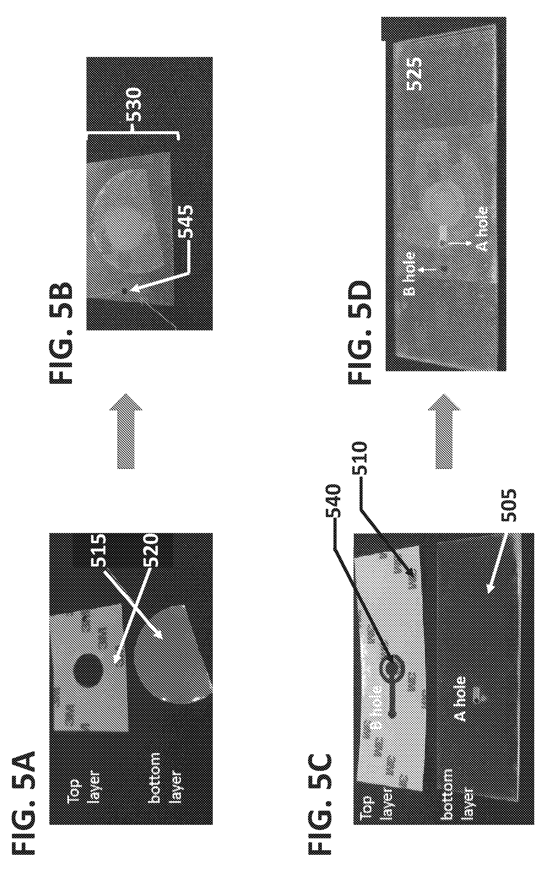
[0052] As shown in FIGS. 5A-5D, a device may comprise a separable sample collection layer (530) and a fixed component (525), with the device configured for use with the separable sample collection layer (530) oriented closest to the sample Flow 1. In this configuration the separable sample collection layer (530) may be separated from the fixed component (525) without inverting the device. As disclosed previously the separable sample collection layer (530) and the fixed component (525) may each be comprised of one or more components. The separable sample collection layer may be configured to rest on top of the fixed component (525), with the separable sample collection layer (530) closest to and facing towards sample flow 1, and the fixed component (525) disposed below the removable layer, furthest from sample Flow 1. The fixed component may be oriented towards the top of the fixed component, oriented facing up, towards the sample source. FIGS. 5A and 5B illustrate a separable sample collection layer (530) formed by a porous membrane (515) and second support layer (520). The second support layer comprises a cutout that forms microchannel B (545). FIGS. 5C and 5D illustrate the fixed component (525) of a device, comprising a first support layer (510) and a solid support (505). In some embodiments the first support layer may comprise a first support layer (510) with cutouts (540) that support the porous membrane. In some embodiments, the cutouts may be configured to form a shape for example a narrow arch shape in the first support layer. In further embodiments the narrow arch shape may be configured to prevent sagging of the porous substrate by introducing complementary channels, thereby creating a narrow arch shape or other connected shape in the support layer that may function as a support of the layers above.
[0053] FIG. 6 illustrates an exploded view of the components present in one or more embodiments of the device. In some embodiments, the device may be comprised of multiple layers. For example, the upper layer may comprise a second support layer (620). The device may be configured such that the second support layer is oriented towards the sample Flow 1. The second support layer may comprise one or more cutouts. For example, the embodiment depicted in FIG. 6, the second support layer may comprise two circular cutouts; one that forms the sample application zone (640) and a second that forms a microchannel (645) for Flow B. In some embodiments, a porous membrane (615) with fixed pore size may be positioned below the second support layer. Further embodiments may be configured such that the second support layer may be directly adhered to the porous membrane through an adhesive layer. In other embodiments, the second support layer may comprise one or more pieces of backing, the backing with the backing disposed between the second support layer and the porous membrane. Backing may comprise release liner. In further embodiments the second support layer and the porous membrane may be configured with any combination of release coatings and/or adhesives, the release coating and/or adhesives may be disposed backing material and/or disposed directly from the porous membrane. In further embodiments the second support layer (620) may be configured such that a separable sample collection layer may be configured comprising the second support layer (620) and the porous membrane (615) such that the separable sample collection layer may first be separated from a fixed component in a first step, and the porous membrane may be separated from the second support layer (620) in a subsequent step.
[0054] In some embodiments, a fixed component may be comprised of a first support layer (610) and a solid support (605). The first support layer may comprise one or more cutouts. The cutouts may comprise one or more defined shapes configured to form one or more microchannels or zones within the device. In some embodiments the first support layer may comprise a sample application zone (640) with diameter and shape resembling that of the cutout in the second support layer (620). In alternate embodiments the sample application zone in the first support layer may have a different size and shape than that of the sample application zone in the second support layer. Similarly, the first support layer may share a similarly shaped cutout (645) that forms a microchannel for Flow B, with similar dimensions to the cutout in the releasable support (620). In alternate embodiments, however, the microchannel (645) for Flow B formed by cutouts in second support layer (620) and first support layer (610), with shapes or sizes that differ between the second support layer (620) and first support layer (610). In further embodiments, as depicted in FIG. 6, the device may comprise a horizontally positioned microchannel (655) within the first support layer (610). The horizontally positioned microchannel may for example connect horizontal and vertical microchannels for sample flow. For example, a horizontal microchannel may connect the vertical microchannel forming the sample application zone (640) and the microchannel (645) configured to accommodate Flow B.
[0055] The first support layer (610) and solid support (605) may form a fixed component, from which a separable sample collection layer may be separated from. In some embodiments, the fixed component may be positioned farthest from sample Flow 1. The solid support (605) may comprise one or more microchannels (650). In some embodiments the solid support may be manufactured without the one or more microchannels, such that one or more microchannels may be added after the solid support (605) is formed. In these instances, the one or more microchannels may be introduced without cutouts or holes in one or more of the device layers or supports. Possible mechanisms for introducing cutouts or holes to the solid support (605) include drilling, boring, coring, and laser cutting among other methods that may be commonly used. In other embodiments, the solid support made with the one or more holes for example the solid support may be cast, or molded with the one or more holes or microchannels in place.
[0056] The device (600), as shown in FIG. 6 may be used to flow sample into and through the device. In some embodiments, sample Flow 1 may comprise one or more components (665) that exceed the pore size of the porous membrane (615). A liquid sample containing suspended cells (665) or other components may be passed through (Flow 1) in an opening or void (640) within the second support layer (620). Particles, cells, or other components suspended in the sample with sizes larger than the pores in the porous membrane may be captured on the face of the porous membrane disposed against the second support layer (620). The fluid as well as sample components smaller than the pore size of the porous membrane (Flow 2), the horizontal flow through the device as depicted by the hollow horizontal arrow in FIG. 6, may pass through the porous membrane and into a horizontally positioned microchannel (655). Some of the Flow 2 may be driven by gravity and flow horizontally through the horizontal microchannel (655) of the first support layer (610) and into a vertically positioned microchannel (650) in the solid support (605). The microchannel (650), as depicted in FIG. 6, may be shallower (a) than the thickness of the solid support (s); thus Flow A, a portion of Flow 2 that moves through the horizontal microchannel (655), with be captured into a microchannel (650) in the solid support (605). In other embodiments, the microchannel in the solid support (650) may be as deep or deeper than the solid support with (a) having a thickness greater than or equal to (s). In some instances the microchannel (650) may be filled with Flow A, causing Flow 2 to retain fluid contact through the horizontal microchannel (655) cut into the first support layer (610) through to the Flow B microchannel (645). The Flow B component of Flow 2, which propagates through the second support layer (620) when suction or capillary action is applied, may be removed via suction, absorption, flow through the device, or other means, to drive the Flow 2 sample through the device.
[0057] FIG. 7 depicts an exploded view of another embodiment of the device. The embodiment depicted in FIG. 7 comprises a porous membrane (715) held between the second support layer (720) and the first support layer (710). Sample Flow 1 may contain cells (765) or other components. In some instances, Flow 1 may be passed through an opening or void (740) within the second support layer (720) in both the embodiments depicted in FIG. 7. Particles, cells, or other components suspended in the sample with sizes larger than the pores in the porous membrane may be captured on the side of the porous membrane connected to the second support layer (720). The fluid as well as sample components (Flow 2) smaller than the pore size of the porous membrane may pass through the porous membrane and into a horizontally positioned microchannel (755). In some embodiments, water may bead up through the porous membrane and keep the sample components that are captured on the porous membrane, for example cells, moist and viable. Flow 2 may be diverted into the horizontally positioned microchannel (755) within the first support layer (710), from where it is diverted into subsequent flows though vertically oriented microchannels. In some embodiments, Flow 2 may be split into a Flow A, which may direct the sample down through a microchannel (750) cut through the solid support (705) and into an absorbent pad (735), and Flow B which may direct the sample upwards though vertically oriented microchannel (745) towards the top of the device (700).
[0058] FIG. 8 depicts an exploded view of yet another embodiment. From top to bottom, with the top of device oriented towards receiving sample Flow 1, the device (800), is comprised of a second support layer (820), a porous membrane (815), a first support layer (810), a solid support (805) and an absorbent pad (835).
[0059] One or more of the layers may comprise microchannels, or cutouts. Cutouts within one or more adjacent layers may be disposed between enclosing layers to form microchannels that different fractions or flows may move through. In some embodiments, for example, the second support layer (820) may comprise multiple microchannels or cutouts. Cutouts may include a smaller microchannel (845) and a larger microchannel (840). In some instances the larger microchannel may be used as the sample application zone and in other embodiments the small microchannel may be used as the sample application zone.
[0060] In other embodiments, the microchannels for Flow A (850) may be in the solid support (805) and the microchannel for Flow B (845) may be disposed in the first support layer (810), second support layer (820) or both the first support layer (810) and the second support layer (820). In further embodiments, suction may be applied to Flow A microchannel (850), the Flow B microchannel (845) or both the Flow A (850) and the Flow B microchannel (845).
[0061] Vertically oriented microchannels may divert the liquid fraction Flow 2 towards the top of the device (845, Flow B) for collection or recycling, or towards the bottom of the device (850, Flow A) for absorption onto an absorbent pad. In some embodiments the horizontally cut microchannel (855) may be in fluid contact with one or more vertically oriented microchannels into which filtered sample, or Flow 2, (i.e. sample flowed through the porous membrane (815)) may move into and through. As depicted in FIG. 6, the Flow 2 components may be diverted through horizontal microchannels (860) in the first support layer (810), which form in the first support layer cutout in the space between the separable sample separation layer (820) and the solid support (805). Horizontal microchannels (860) may be configured to prevent sagging of the porous substrate by introducing complementary channels, thereby creating a narrow arch shape (870) or other connected shape that acts as a support of the layers above. FIG. 8 further depicts an exploded view of another embodiment of the lollypop shape. The narrow arch shape (870) or other cutout may be formed by making cutouts in the support layer, which are established by extending the first support layer (810) into the horizontal microchannel (860) with microchannels along a portion of its side. In some instances shapes such as the narrow arch shape (870) may provide extra structural support for porous membrane (815) directly above it. Extra support may function to reduce the likelihood of the porous membrane (815) to sag into the larger microchannel (840). Flow 2 may then move out of the top of the device; in this case the flow (B flow) may occur through a microchannel (845) constructed from cutouts in multiple layers, with fluid contact between the first support layer (810) and the second support layer (820). In some embodiments, water may bead up through the porous membrane onto at least a portion of the collected cells or sample components that did not pass through the porous membrane (815) and keep the sample components that are captured on the porous membrane, for example cells, moist and viable. In some embodiments Flow 2 may also be diverted (A flow) towards the bottom of the device; this may for example occur through a microchannel (850) disposed partially or entirely through the solid support (805). In some embodiments the microchannel (850) may be disposed entirely through the solid support and collected onto an absorbent pad (835) on the side of the solid support layer opposite the first support layer; in other embodiments the microchannel (850) may be disposed only partially through the solid support layer without fluid connection with the absorbent pad.
[0062] In some embodiments, one or more layers of the device may be configured to be separable. In some instances, for example, layers of the device may be reversibly adhered to one another. For example, a first support layer (810) and a second support layer (820) may each comprise a release liner. In some embodiments any one of the aforementioned device components may comprise an adhesive surface. The adhesive surface may be disposed against another component of the device comprised of a release liner. Release layer may comprise a solid material or backing, coated with a low surface energy material or release coating. In some instances, one or more of the support layers may comprise a release liner. For example the first support layer (810), second support layer (820) may each comprise a release liner. In further embodiments, a porous membrane (815) may be disposed between a first support layer (810) and a second support layer (820). A porous membrane (815) may be reversibly affixed using an adhesive coating disposed against the release liner. In some instances the adhesive coating may be one side of the porous membrane, while still allowing a central region of the porous layer exposed without the adhesive coating and/or the release liner, for example on the second support layer side of the porous membrane dispose against a first support layer comprising at least a partial covering release liner, with the release coating of the release liner oriented towards the porous membrane and adhered to the second support layer. In some embodiments at least a portion of the second support layer may comprise a second adhesive surface with an adhesive surface disposed against the release coating side of a release liner. In further configurations a porous membrane (815) may be disposed between two support components, for example a second support layer (820) and a first support layer (810). In further embodiments, the porous membrane may have a diameter that exceeds the sample application zone (840), such that the surface of the porous membrane (815) that exceeds the sample application zone may be coated with an adhesive and sandwiched between one or more support layers. Adhesive on the porous membrane may be used to hold the porous membrane against release liner in one or more of the support components, which may include a first support layer (810) and a second support layer (820). In further embodiments, a porous membrane (815) may be sandwiched between two supports, for example a second support layer (820) and a first support layer (810), and one support layer, for example the first support layer (810), may have adhesive holding it to a solid support (805). In some embodiments the first support layer (810) may be irreversibly bound to the solid support (805). In further embodiments, one or more of the individual components or combined component layers may comprise tabs or other extended regions that facilitate separation of the layers. In some embodiments the tabs may be composed of a material that differs from other materials within the sample device. Further embodiments may comprise one or more components that provide color based indicators, for example transparent colored films or plastics or other backings that may be coated to facilitate easy identification and separation of the layers. One or more components or layers of the device may further comprise lettering, shapes, or other makings or indications that guide a user in the location, identification, and/or separation of one or more components or layers within the device.
[0063] Examples of dimensions for components of the device are illustrated in FIGS. 9A, 9B, 9C and 9D. FIG. 9A represents the second support layer (920), with microchannel (945) cutout and the sample application zone (940). The diameter of (B), D.sub.B, may be greater than or equal to 10 mm, 9 mm, 8 mm, 7 mm, 6 mm, 5 mm, 4 mm, 3 mm, 2 mm, 1 mm, 0.5 mm, 0.25 mm or 0.1 mm in diameter. The diameter of D.sub.release may be greater than or equal to 30 mm, 25 mm, 20 mm, 15 mm, 10 mm, 5 mm, or 3 mm in diameter. A first support layer (910) with relevant dimensions, is illustrated in FIG. 9B. The dimensions of the sample application zone (940), include D.sub.base which may or may not be equivalent to D.sub.release. D.sub.base may be greater than or equal to 30 mm, 25 mm, 20 mm, 15 mm, 10 mm, 5 mm, or 3 mm in diameter. Sub-microchannels and cutouts in the D.sub.base region include microchannels with the widths defined as the outer diameter (Dout) and the inner diameter (Din). Dout and Din may be of equal length or different lengths. Dout and/or Din may be less than or equal to 5 mm, 4 mm, 3 mm, 2 mm, 1 mm or 0.5 mm. It may be optimal to keep Din as small as possible to increase the area for water to form, while still providing the structural support to prevent the porous substrate from sagging. A horizontal microchannel (955) may connect the sample application zone with the vertical microchannels B and A. The horizontal microchannel may have a width D.sub.F. D.sub.F may have a width of less than or equal to 10 mm, 6 mm, 4 mm, 2 mm, 1 mm or 0.5 mm. The length of this horizontal microchannel (955) may be defined as L.sub.F. L.sub.F may have a length of greater than or equal to 20 mm, 15 mm, 10 mm, 5 mm, 3 mm, or 1 mm. FIG. 9C illustrates a solid support (905) with microchannel (A). Microchannel A may have a diameter D.sub.A. D.sub.A may have a width of greater than or equal to 10 mm, 9 mm, 8 mm, 7 mm, 6 mm, 5 mm, 4 mm, 3 mm, 2 mm, 1 mm, 0.5 mm, 0.25 mm or 0.1 mm . The length between the sample application zone's (940) closest edge to microchannel A and microchannel A may be defined as L.sub.A. L.sub.A may have a diameter of greater than or equal to 15 mm, 10 mm, 5 mm, 3 mm, 2 mm, or 1 mm. FIG. 8D illustrates a porous membrane (915), with diameter D.sub.membrane. D.sub.membrane may be greater than or equal to 75 mm, 60 mm, 55 mm, 40 mm, 25 mm, 20 mm, 15 mm or 10 mm in diameter and may be greater than the diameter of D.sub.base and/or D.sub.release.
[0064] In some embodiments, the device may be configured to use pressure to drive sample through the device. Pressure of less than 100 mm-H.sub.2O, 50 mm-H.sub.2O, 40 mm-H.sub.2O, 30 mm-H.sub.2O, 20 mm-H.sub.2O, 10 mm-H.sub.2O, or 5 mm-H.sub.2O may be applied to a microchannel (B) to drive Flow 2 through the device. Pressure values may be configured or adapted to effectively remove solution with minimal disruption to the cell, particles or other matter collected on the porous membrane. In these embodiments, sample would be applied to the top of the device (Flow 1), particle or sample components greater than the size of the pores may be trapped in the porous membrane and liquid solution (Flow 2) as well as any sample components smaller than the pores, may travel through the porous membrane into the horizontal microchannel (955). Some of Flow 2 may flow into microchannel A, where the fluid may be trapped to retain fluid contact between the microchannels of the device, and facilitate motion of fluid through the device during application of suction. Top and bottom views of microchannels A and B are shown in FIGS. 9, 10, and 11. Microchannel (B) may be accessible from the top of the device where suction may be applied, and microchannel (A) may or may not be visible from the bottom of the device. In some embodiments the microchannel (A) may be disposed completely through the bottom of the device.
[0065] FIG. 10 illustrates a non-limiting embodiment of the device created from components depicted in FIGS. 8-9. FIG. 10A shows the separable sample collection layer(1030) comprising the porous membrane and one or more second support layers, separated from the fixed component (1025) comprising one or more first support layer and/or solid supports. In some instances the separable sample collection layer (1030) may be the top layer and the fixed component (1025) may be the bottom layer, as shown in FIG. 10B. In further embodiments the separable sample collection layer (1030) may be the bottom layer and the fixed component (1025) may be the top layer. In some instances the bottom component of the device may comprise a fixed component (1025) or a separable sample collection layer (1030). Correspondingly, embodiments with a bottom layer comprising a fixed component (1025) may have a top layer comprising a removable layer, and embodiments with a bottom layer of the device comprising a separable sample collection layer (1030) may have a top layer comprising a fixed component (1025).
[0066] As illustrated in FIG. 10C, in some instances the separable sample collection layer (1030) may comprise a microchannel (B) for Flow 2 to move through the device. In further embodiments Flow 2 may be shunted or diverted into multiple sub-flows for example Flow A and Flow B. Flow B may be diverted through the top layer through a microchannel (B). In some instances the separable sample collection layer (1030) may be the top layer. In further instances, the removable top layer may comprise a microchannel (B) for diverting Flow B through the device. In alternate incidences the top layer may be the fixed component (1025). In further embodiments the top layer may be a fixed component (1025) and comprise a microchannel (B) through which sample is diverted or separated into a Flow B. In further embodiments the bottom layer of the device may comprise a microchannel (A).
[0067] FIG. 10D illustrates that a sample may move through both the bottom and the top of the device using microchannels in the top or the bottom of the device. For example the microchannel shown in the top of the device (B hole) may be in fluid connection with sample that has traveled through the sample application zone and one or more horizontally oriented microchannels into a vertically oriented microchannel (B hole) that exposes sample to the top of the device. The device may comprise further embodiments, wherein a microchannel (A hole) is disposed through the bottom of the device, such that sample can move into and directly down to and through the bottom of the device. In one or more of the disclosed embodiments microchannels in the device including any combination of A hole, B hole or any prior mentioned microchannels. In some instances, for example in the illustrated embodiment, Flow 2 or components of Flow 2 (i.e. Flow A and/or Flow B) may be directed, diverted or shunted through the device. In further embodiments, the device may be configured such that one or more chambers in one or more components of the device or configured to retain fluid contact and facilitate sample movement through the device.
[0068] In some instances microchannels in the device may comprise one or more fixtures, adaptors, luers, luer locks, manifolds, stop cocks, tubing, barbs or mechanisms for controlling sample flow or retaining fluid connection or contact with the sample. Further embodiments may comprise perfusion controls systems, configured to interface with one or more microchannels in the device and create flow of fluid through gravity, pressure or other means. Perfusions systems may rely on gravity, pressure or other means including syringes or vacuum suction to drive sample through one or more microchannels in the device. In some instances or embodiments the device or attachments to the device may be configured to connect to one or more apparatuses and/or control units for modulating and/or applying pressure or suction to a microchannel.
[0069] FIG. 11 provides an example of an embodiment configured for moving sample that the device. In some instances Flow 1 may comprise components for example cells, that may be desirable and in need of separation from other components of the device. Flow 1 may be applied to a sample application zone, as shown. Large components of the sample, for example cells, may be captured at the porous membrane of the device, and remaining components of the sample may flow into and through the device through one or more microchannels. Horizontal microchannels may be disposed within the device. Sample components may move into a horizontal microchannel, and from there move out of vertically oriented microchannels, for example (B, 1145) or (A, 1150). In some instances, uncollected sample may flow through the device and towards the top of the device (B, 1145). In other instances, or further embodiments, uncollected sample may flow through the device and towards the bottom of the device (A, 1150).
[0070] FIG. 12 illustrates phases or steps for using one or more embodiments in a specific application. In Phase 1, sample Flow 1 may be applied to the device on the sample application zone (1240). Liquid sample or uncollected components of the sample may travel through the porous membrane and into a horizontally oriented microchannel (1255) designed to collect the sample and shuttle it through to a microchannel that exposes the sample to the top of the device (B). The microchannel may be configured with a fixture that facilitates the application of pressure for example perfusion tubing, plastic valves, or luer components (1255). Sample collected on the porous membrane (1215) may be cleaned or treated using solvents, solutions, and/or other components. In some embodiments, the sample may be treated with agents, which may include buffers (i.e. washing buffers), foam reducing agents or defoam reagents including FoamAway or solutions containing simethicone emulsion, fixatives, staining reagents, solutions comprising antibodies including primary antibodies (i.e. CK20 rabbit anti-human, CD45 rat anti-human), secondary antibodies (i.e. Goat anti-rabbit Alexa 568, Goat anti-Rat Alexa 488), or any other antibodies including mono-clonal or poly-clonal, antibody staining reagents and/or other components. Liquid components that are not collected on or in the porous membrane may flow through the device and may be removed through one or more of the microchannels in the device. Methods or external apparatuses may be used to apply forces that drive sample through the device. In some embodiments, forces may comprise vacuum suction and/or pressure including air pressure or fluid pressure to drive sample through the device (Flow B). In some instances, as shown, the device may be configured with means to apply vacuum suction to remove sample and drive it through the device (1275).
[0071] Component of a device may be used in a second phase or Phase 2. For example, in Phase 2 the separable sample collection layer comprising the porous membrane and the sample may be separated from the fixed component of the liquid and transferred to a new surface. In some instances, the separable sample collection layer may be transferred to a glass slide for imaging. In other embodiments, the porous membrane may be transferred without a support layer to a glass slide (1270) for imaging. Transfer of the removable layer is facilitated by the release paper, which enables removal of the porous layer with minimal jarring to the sample thereupon. The release paper allows for minimal but sufficient adhering of the porous layer (815) to the one or more support layers (810, 820). Removal of the sample porous layer (815) from the one or more support layers (810, 820) (e.g. gripping the sample collection or porous membrane layer using tweezers or forceps and then peeling off the membrane on layer at a time) with minimal jarring increases the likelihood that CTC cells will remain viable after the transfer step, and for additional subsequent treatment steps. Phase 2 may involve subsequent treatment steps, for example drying the sample; using reagents, fixatives, or other components that do not to be removed from the sample. Further embodiments may enter into a third phase or Phase 3. Phase 3 may involve additional treatment steps, including fixing the sample or preserving the sample. Phase 3 methods of trapping the sample may be designed to reduce or eliminate contamination and/or exposure of the sample. In some embodiments, for example, Phase 3 may involve applying an additional glass slide or a glass coverslip for eliminating sample exposure. In other instances, the porous membrane (1215) maybe separated from the separable sample collection layer (1230) and the substrate or glass slide (1270) and transferred to another surface.
[0072] In some embodiments a device, as disclosed in the present application, may be used to perform immunohistochemistry. In these instances, liquid sample comprising suspended cells may be applied to a porous membrane (1305), Cell fixing reagent (1310), for example PFA, may be added and filtered through the porous membrane through horizontally, vertically, or a combination of horizontally and vertically oriented channels. The cells collected on the porous membrane may be washed with a buffer (1315), for example with a PBS buffer, prior to adding surfactant (1320) followed by another washing step with buffer (1325). Excess liquid reagents or solution, which may include buffer or surfactant, may move through the channels allowing the cells to be separated from the solution yet remain viable. A blocking agent (1330), for example BSA (bovine serum albumin) may be added, followed by PBS buffer (1335). Primary antibody may be applied (1340), and an additional washing step (1345) may occur prior to the addition of a secondary antibody (1350) and another washing step with buffer (1355). The removable layer may be separated from the fixed layer (1360) using the release paper, and the sample may be transferred to a new slide (1365). In some embodiments the sample may be transferred with the cells exposed up away from the glass surface, and in other embodiments the cells may be oriented face down with the cells directly against the glass surface. Mounting agents (1370) may be applied to the cells using the porous membrane before the sample is covered with a coverslip (1375) and imaged (1380).
[0073] In further alternate embodiments, a device as disclosed may be used to treat cells with a defoam reagent before subsequent steps, for example imaging. In some embodiments, liquid sample comprising foam and cells may be applied to a porous membrane (1405). Defoam reagent may be added to the membrane (1410) followed by washing buffer (1415), allowing the cells to remain on the porous membrane while the buffer or defoam moves through channels in the device, away from the cells. Cell fixing reagent may be applied (1420), followed by wash with a buffer (1425), followed by the addition of surfactant (1430), and an additional wash with buffer (1435). Blocking agent may be added (1440), followed by a buffer wash (1445), and the addition of primary antibody (1450) before a subsequent washing step (1455) and addition of secondary antibody (1460). Washing buffer may be added again (1465), before the separable layer is removed from the fixed layer (1470). Finally the separable layer may be transferred to a slide before (1475) the addition of mounted agent (1480).
[0074] While preferred embodiments of the present invention have been shown and described herein, it will be obvious to those skilled in the art that such embodiments are provided by way of example only. Numerous variations, changes, and substitutions will now occur to those skilled in the art without departing from the invention. It should be understood that various alternatives to the embodiments of the invention described herein may be employed in practicing the invention. It is intended that the following claims define the scope of the invention and that methods and structures within the scope of these claims and their equivalents be covered thereby.
* * * * *
D00001
D00002
D00003
D00004
D00005
D00006
D00007
D00008
D00009
D00010
D00011
D00012
D00013
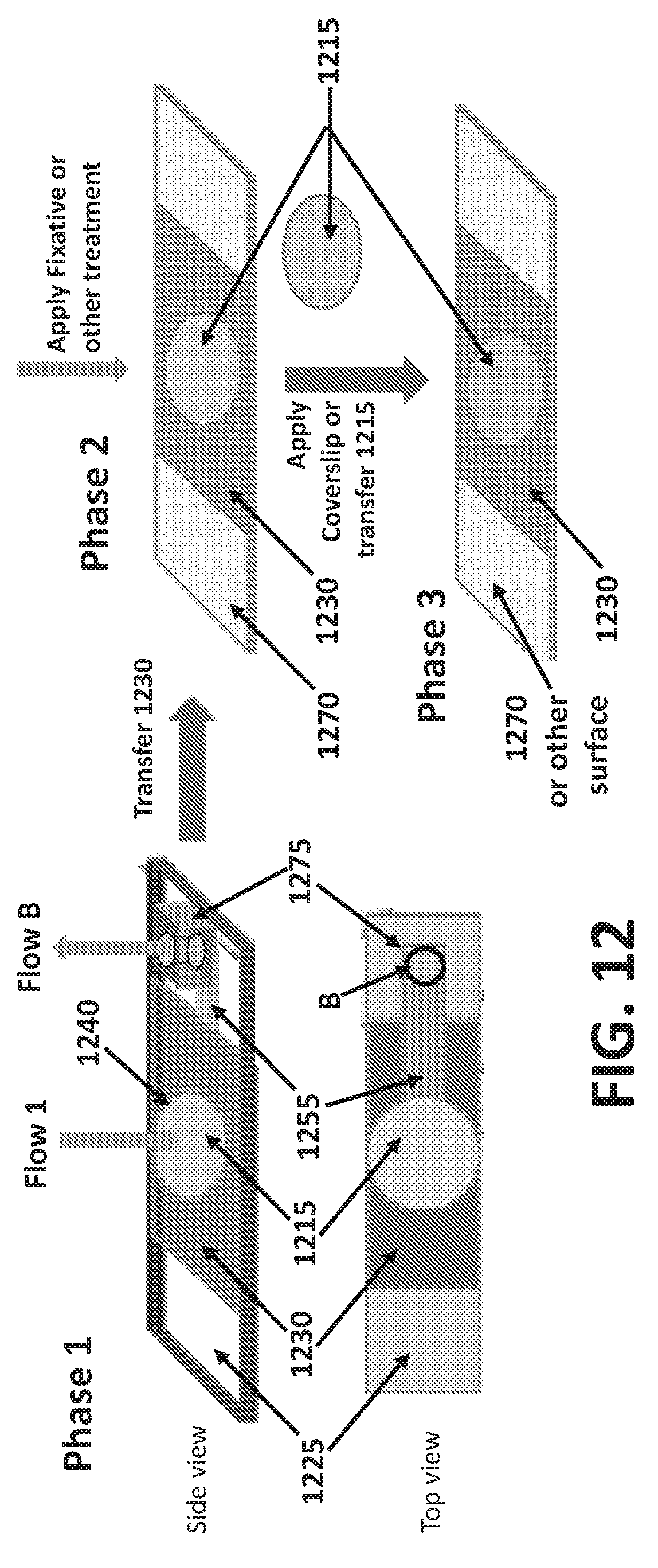
D00014

D00015
XML
uspto.report is an independent third-party trademark research tool that is not affiliated, endorsed, or sponsored by the United States Patent and Trademark Office (USPTO) or any other governmental organization. The information provided by uspto.report is based on publicly available data at the time of writing and is intended for informational purposes only.
While we strive to provide accurate and up-to-date information, we do not guarantee the accuracy, completeness, reliability, or suitability of the information displayed on this site. The use of this site is at your own risk. Any reliance you place on such information is therefore strictly at your own risk.
All official trademark data, including owner information, should be verified by visiting the official USPTO website at www.uspto.gov. This site is not intended to replace professional legal advice and should not be used as a substitute for consulting with a legal professional who is knowledgeable about trademark law.