Gas Feed Unit For An Exhaust-gas Analysis Unit For The Measurement Of Exhaust Gases Of Internal Combustion Engines
DICKOW; ACHIM
U.S. patent application number 16/341922 was filed with the patent office on 2019-08-08 for gas feed unit for an exhaust-gas analysis unit for the measurement of exhaust gases of internal combustion engines. This patent application is currently assigned to AVL EMISSION TEST SYSTEMS GMBH. The applicant listed for this patent is AVL EMISSION TEST SYSTEMS GMBH. Invention is credited to ACHIM DICKOW.
| Application Number | 20190242786 16/341922 |
| Document ID | / |
| Family ID | 60083931 |
| Filed Date | 2019-08-08 |
| United States Patent Application | 20190242786 |
| Kind Code | A1 |
| DICKOW; ACHIM | August 8, 2019 |
GAS FEED UNIT FOR AN EXHAUST-GAS ANALYSIS UNIT FOR THE MEASUREMENT OF EXHAUST GASES OF INTERNAL COMBUSTION ENGINES
Abstract
A gas feed unit for an exhaust gas analysis unit includes a measurement unit for analysing a sample gas, a connection line arranged so that a calibration gas line, a purge gas line, and a sample gas line opens thereinto and which fluidically connects to the measurement unit, a shut-off valve arranged in each of the calibration gas line, the purge gas line, and the sample gas line, a pump which delivers the sample gas from an exhaust gas source, an outflow line with an outflow nozzle and a shut-off valve, and an outflow nozzle arranged at an end of the connection line opposite to the measurement unit. The outflow line branches off from the connection line. The sample gas line is arranged to open into the connection line between the measurement unit, the calibration gas line, and the purge gas line.
| Inventors: | DICKOW; ACHIM; (VELBERT, DE) | ||||||||||
| Applicant: |
|
||||||||||
|---|---|---|---|---|---|---|---|---|---|---|---|
| Assignee: | AVL EMISSION TEST SYSTEMS
GMBH NEUSS DE |
||||||||||
| Family ID: | 60083931 | ||||||||||
| Appl. No.: | 16/341922 | ||||||||||
| Filed: | September 27, 2017 | ||||||||||
| PCT Filed: | September 27, 2017 | ||||||||||
| PCT NO: | PCT/EP2017/074500 | ||||||||||
| 371 Date: | April 15, 2019 |
| Current U.S. Class: | 1/1 |
| Current CPC Class: | F01N 11/005 20130101; G01M 15/102 20130101; G01N 1/2252 20130101; G01M 15/10 20130101 |
| International Class: | G01M 15/10 20060101 G01M015/10; F01N 11/00 20060101 F01N011/00 |
Foreign Application Data
| Date | Code | Application Number |
|---|---|---|
| Oct 17, 2016 | DE | 10 2016 119 713.0 |
Claims
1-12. (canceled)
13. A gas feed unit for an exhaust gas analysis unit for a measurement of exhaust gases of an internal combustion engine, the gas feed unit comprising: a measurement unit for the analysis of a sample gas; at least one calibration gas line; a purge gas line; a sample gas line; a common connection line arranged to have each of the at least one calibration gas line, the purge gas line, and the sample gas line open thereinto and to provide a fluidic connection to the measurement unit; a shut-off valve arranged in each of the at least one calibration gas line, the purge gas line, and the sample gas line, each of the shut-off valves being configured so that a flow of the sample gas, a flow of a calibration gas, and a flow of a purge gas is shut off or released; a pump configured to deliver a flow of the sample gas from an exhaust gas source; an outflow line comprising an outflow nozzle and a shut-off valve arranged therein, the outflow line being arranged to branch off from the common connection line; and an outflow nozzle arranged at an end of the common connection line opposite to the measurement unit, wherein, the sample gas line is arranged to open into the common connection line between the measurement unit, the at least one calibration gas line, and the purge gas line.
14. The gas feed unit as recited in claim 13, wherein, the sample gas line comprises an opening into the common connection line, and the outflow line is arranged to branch off from the common connection line between the opening and the measurement unit.
15. The gas feed unit as recited in claim 14, wherein, the shut-off valve arranged in the outflow line is open when one shut-off valve of the at least one calibration gas line is open, and the shut-off valve arranged in the outflow line is closed when the shut-off valve of the sample gas line is open.
16. The gas feed unit as recited in claim 14, wherein the purge gas line is arranged to open into the common connection line between the at least one calibration gas line and the opening of the sample gas line.
17. The gas feed unit as recited in claim 14, further comprising: a pressure control valve arranged in the common connection line downstream of the at least one calibration gas line and the purge gas line.
18. The gas feed unit as recited in claim 17, further comprising: a shut-off valve arranged in the common connection line.
19. The gas feed unit as recited in claim 18, wherein the shut-off valve arranged in the common connection line is arranged downstream of the pressure control valve and upstream of the opening of the sample gas line.
20. The gas feed unit as recited in claim 13, wherein, the gas feed unit comprises a plurality of calibration gas lines which are configured so that different concentrations of the calibration gas of a gas component to be measured can be introduced therein, and the plurality of calibration gas lines are each arranged to open into the common connection line at a distance to the measurement unit which increases with an increasing concentration of the gas component to be measured.
21. The gas feed unit as recited in claim 13, further comprising: a sample gas main line; a back pressure controller arranged at an end of the sample gas main line; and a plurality of measurement units which are respectively fluidically connected to the sample gas main line via the sample gas line and the common connection line, wherein, a pressure in the sample gas line is configured to be controlled via the back pressure controller at the end of the sample gas main line.
22. The gas feed unit as recited in claim 13, wherein the pump which is configured deliver the flow of the sample gas is arranged upstream of the measurement unit.
23. The gas feed unit as recited in claim 22, wherein the pump is configured to deliver the sample gas with a flow rate of 2.5 to 3.0 l/min.
24. The gas feed unit as recited in claim 13, wherein an internal diameter of the sample gas line and of the common connection line is each approximately 2 to 4 mm.
Description
[0001] The invention relates to a gas feed unit for an exhaust gas analysis unit for the measurement of exhaust gases of internal combustion engines, having a measurement unit for the analysis of sample gas, a calibration gas line, a purge gas line and a sample gas line which open into a common connection line by means of which a fluidic connection to the measurement unit can be produced, shut-off valves in the calibration gas line, the purge gas line and the sample gas line by means of which shut-off valves the sample gas flow, the calibration gas flow and the purge gas flow can be selectively shut off or released, and a pump for delivering the sample gas flow out of an exhaust gas source.
[0002] Exhaust gas analysis units are used at roller test benches of motor vehicles, for example. The analysis cabinets used for this purpose contain, on the one hand, the drive and electronic systems in the exhaust gas measuring system which may be configured as a CVS system (constant volume sample) but may also serve for analyzing undiluted exhaust gas, for example, and, on the other hand, the measurement units required for analyzing the exhaust gas for determining the amount of harmful substances in the exhaust gas, such as a flame ionization detector analyzing units for the determination of hydrocarbons or via a gas chromatograph for the determination of the amounts of methane, chemiluminescence detector analyzing units for the determination of the amounts of nitrogen oxide in the exhaust gas, infrared detector analyzing units for the determination of various active components, such as carbon monoxide, carbon dioxide or hydrocarbon compounds in the exhaust gas, for example. Accordingly, the control cabinet is connected to the sampling probes of the exhaust gas take-off system via lines which are connected to the control cabinet via corresponding couplings.
[0003] The measurement units are supplied via gas feed units by means of which either sample gas to be analyzed, calibration gas or purge gas is fed.
[0004] The through-flow rates in these gas feed units normally amount to approximately 10 to 12 l/min. However, in modern internal combustion engines the amount of exhaust gases is continuously reduced due to a better and cleaner combustion. In addition, not only the composition of the actually emitted exhaust gas is measured, but also the composition of the exhaust gas recirculated via an exhaust gas recirculation line is to be analyzed, for example. Especially this recirculated exhaust gas always influences the subsequent combustion processes such that the extraction can be carried out merely in very small through-flow rates since otherwise the effect on the engine would be so large that the combustion data would no longer correspond to those of a normal operation. If information regarding the composition of this exhaust gas is required to be submitted with very small delays of 1 second, for example, an extremely strong dilution would have to be used for obtaining adequate through-flow rates for the analysis unit. However, this results in very inaccurate measuring values since the limits of the measuring accuracy of existing measurement units are reached when such strong dilutions are used. Consequently, falsifications of the measuring results are considerably increased due to contamination by the gas previously supplied by the gas feed unit.
[0005] It is therefore an object to provide a gas feed unit for the measurement of exhaust gases of internal combustion engines, which have small through-flow rates but nevertheless provide the measuring gas to the measurement units as rapidly as possible such that they obtain accurate measuring values, wherein an effect on the internal combustion engine must be minimized.
[0006] This object is achieved with a gas feed unit for an exhaust gas analysis unit for the measurement of exhaust gases of internal combustion engines having the features of claim 1.
[0007] Due to the fact that the sample gas line opens into the connection line between the respective measurement unit and the calibration gas line as well as the purge gas line, wherein at the end of the connection line opposite the measurement unit an outflow nozzle is arranged and an outflow line branches off the connection line and contains an outflow nozzle and a shut-off valve, at the beginning of the measurements only very small volumes filled with purge gas, calibration gas or sample gas of previous measurements must be evacuated to allow for the sample gas flow to be measured to reach the measurement unit. Further, falsifications of the measurements are considerably reduced since no sample gas must flow past the connection lines of the purge gas or the calibration gas. This leads to very rapidly obtained and correct measuring results and allows for reduction of the through-flow rate due to the small dead volumes. In addition, the outflow nozzle arranged at the end of the connection line opposite the measurement unit prevents the sample gas flow from being pressed into the connection line towards the purge gas and calibration gas connections and from flowing from there back towards the measurement unit, whereby the measuring results would be affected. Instead, the sample gas, which reaches the section filled with the purge or calibration gases, flows to the outside via the nozzle and thus removes the calibration and purge gases from these line sections. Via the outflow nozzle and the shut-off valve in the outflow line, gas having previously been present in the line is rapidly removed from the connection line, which gas, during the switching between the various gas flows, can flow out via the nozzle when the valve is open such that merely the respective residual gas in the measurement unit must be removed from the overall system. In addition, purging can be carried out with a larger gas flow than the gas flow for which the measurement unit is designed.
[0008] Preferably, the outflow line branches off the connection line between the opening of the sample gas line and the measurement unit. Accordingly, purge or calibration gas present in the connection line is displaced from the line by the sample gas without having to flow through the measurement unit. If a larger amount of the sample gas is delivered than can flow to the measurement unit through a flow restrictor, residual gas is removed from both the line and the measurement unit itself within a very short time such that reliable measuring results are very rapidly obtained.
[0009] In addition, it is advantageous when the shut-off valve in the outflow line is open when one of the shut-off valves of the calibration gas line is open, and is closed when the shut-off valve of the sample gas line is open. Thus the measurement unit is very rapidly ready for use after the purging process.
[0010] According to an advantageous embodiment, the purge gas line opens into the connection line between each calibration gas line and the opening of the sample gas line. As a result, no gas residues from the calibration gas line can be entrained during introduction of the purge gas. Instead, the calibration gas is completely removed from the connection line by the purge gas flow.
[0011] Further, it is advantageous that the gas feed unit comprises a plurality of calibration gas lines into which calibration gases of different concentrations of the gas component to be measured are adapted to be introduced, wherein the calibration gas lines open into the connection line at a distance to the measurement unit growing with an increasing concentration of the gas component to be measured. Thereby, no contamination by more highly concentrated calibrating gas can occur after a one-time removal of the previously used calibration gas from the connection line since the low-dose calibration gas is not fed past the line of the more highly dosed calibration gas. Instead, this more highly dosed calibration gas can be completely discharged at the opposite end of the connection line via the outflow nozzle.
[0012] Preferably, a pressure control valve is arranged in the connection line downstream of the calibration gas line and the purge gas line. Accordingly, by means of this valve both the pressure of the various calibration gases and of the purge gas in the connection line can be controlled.
[0013] According to an advantageous embodiment, a shut-off valve is arranged in the connection line. Accordingly, undesired flows through the connection line can be stopped. For example, the shut-off valve is closed during the analysis of the sample gas and is open during the calibration and purging. Thus the sample gas is rapidly removed from the line such that after a short time purging and calibration can be carried out. Due to the small sample gas flows in the exhaust gas analysis unit an additional outflow of the sample gas in front of the measurement unit is prevented and thus an adequate supply of the measurement unit with a sample gas for analysis purposes is ensured.
[0014] According to a further embodiment, the shut-off valve is arranged in the connection line downstream of the pressure control valve and upstream of the opening of the sample gas line. Thus during the measurements of the sample gas, the connection line can be closed towards other lines such that the sample gas does not flow through additional volumes. Accordingly, within a very short time accurate measuring results are obtained even in the case of small amounts of exhaust gas.
[0015] According to another advantageous aspect of the invention, the exhaust gas analysis unit comprises a plurality of measurement units which are respectively fluidically connected to a sample gas main line via a sample gas line and a connection line, wherein a pressure in the sample gas lines is adapted to be controlled via a back pressure controller at the end of the sample gas main line. Thus the sample gas pressure can be controlled for a plurality of measurement units via merely one pressure controller during the measurements in the analysis unit, whereby components can be saved.
[0016] In addition, the pump for delivering the sample gas flow is preferably arranged upstream of the measurement units. This prevents a contamination of the sample gas flow via small leaks in the analysis unit since no gas is taken in but pressed through the system. Thereby, an overpressure is produced in the system, which reliably prevents such inflow from outside and allows the gas flows to escape via the nozzles.
[0017] Advantageously, this pump delivers a sample gas flow of 2.5 to 3.0 l/min. such that a relatively compact membrane pump can be used. In the case of withdrawal of such a small amount of gas, exhaust gas from the exhaust gas recirculation duct can also be analyzed, for example, without any effects on the operating state of the engine to be tested having to be expected.
[0018] For realizing such a small through-flow rate while ensuring an adequate velocity in the lines, the inner diameter of the connection line and the sample gas line is approximately 2 to 4 mm.
[0019] Thus a gas feed unit for an exhaust gas analysis unit for the measurement of exhaust gases of internal combustion engines is provided by means of which even in the case of very small through-flow rates accurate measuring values can be obtained at a very short response time by preventing falsifications of the measuring values by contamination from outside or by purge or calibrating gases. Additionally, an effect of the sampling on the internal combustion engine is excluded.
[0020] An exemplary embodiment of the gas feed unit for an exhaust gas analysis unit for the measurement of exhaust gases of internal combustion engines according to the invention is illustrated in the FIGURE and described below.
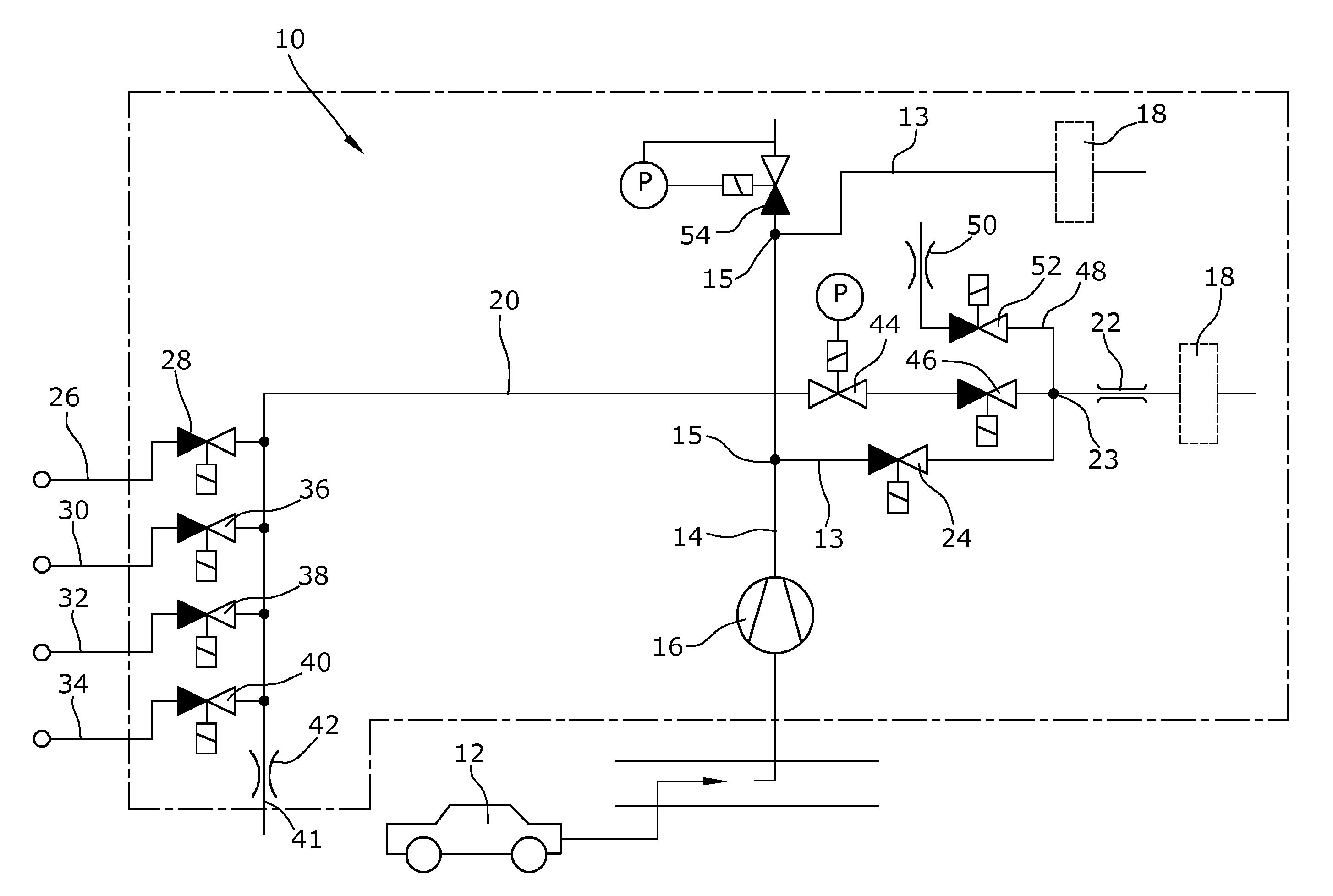
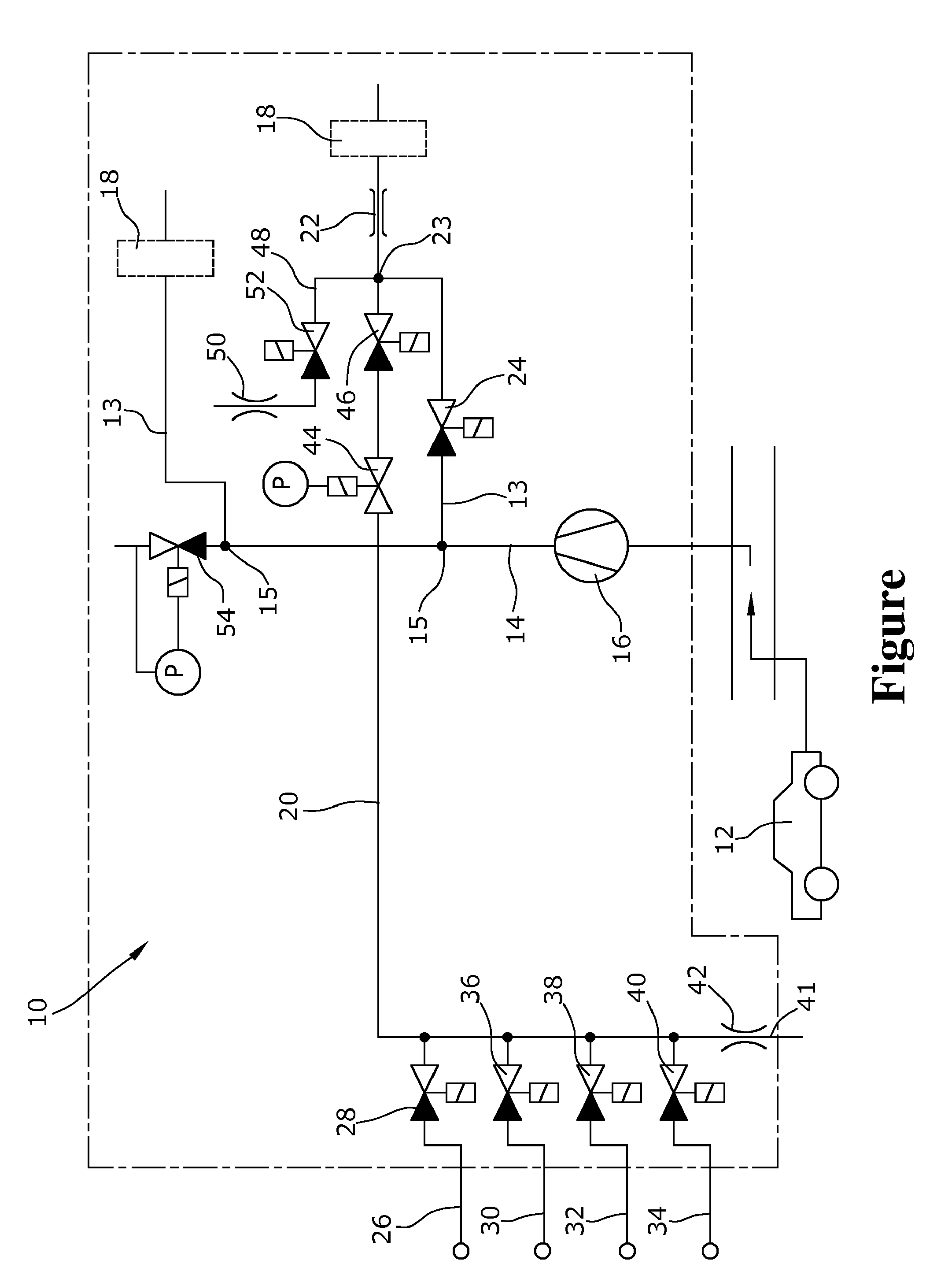
[0021] The FIGURE shows a schematic flow diagram of a gas feed unit for an exhaust gas analysis unit according to the invention.
[0022] Exhaust gas analysis units 10 are supplied with an exhaust gas from an exhaust gas source 12, such as an internal combustion engine of a motor vehicle. Depending on the system used, this exhaust gas is supplied to the analysis unit 10 either in a diluted or an undiluted form. For this purpose, the sample gas is delivered either directly from a take-off line or from sample gas bags into a sample gas main line 14 by means of a pump 16 which, in the present exemplary embodiment, presses the sample gas into the sample gas main line 14 such that a contamination of the sample gas due to leaks in the sample gas main line 14 and the adjoining sample gas lines 13 can be excluded.
[0023] The sample gas main line 14 comprises different branches 15 from which the sample gas flow can be delivered to various measurement units 18 via the sample gas lines 13, which measurement units are usually arranged in a switch cabinet. These measurement units are a flame ionization detector analyzing unit for the determination of hydrocarbons, a chemiluminescence detector analyzing unit for the determination of the amounts of nitrogen oxide in the exhaust gas or an infrared detector analyzing unit for the determination of various active components, such as carbon monoxide, carbon dioxide or hydrocarbon compounds in the exhaust gas, for example, and are respectively supplied via their own connection line 20 either with the sample gas or with a purge gas or one or a plurality of calibration gases. For respectively feeding a proper amount of measurement gas to the measurement unit 18, in front of the measurement unit 18 a throttle valve or capillary tube 22 is provided by means of which the gas flow is restricted.
[0024] In the section of the sample gas line 13 located behind the branch 15, a shut-off valve 24 is arranged via which the sample gas line 13 is adapted to be shut off in front of its opening 23 into the connection line 20.
[0025] Upstream of the opening 23 of the sample gas line 13, a purge gas line 26 opens into the connection line 20, via which purge gas, e.g. nitrogen, can be delivered towards the measurement unit 18. In this purge gas line 26, too, a shut-off valve 28 for opening and closing the purge gas line 26 is located. In the present exemplary embodiment, upstream of the purge gas line 26 three calibration gas lines 30, 32, 34 open into the connection line 20, wherein the distance of the opening of the respective calibration gas line 30, 32, 34 into the connection line 20 to the measurement unit 18 grows with increasing concentration of the calibration gas. The concentration is respectively raised to the power of 10 at a growing distance to the measurement unit 18, for example. In all calibration gas lines 30, 32, 34 a shut-off valve 36, 38, 40 is located via which the respective calibration gas flow can be released or stopped.
[0026] At the end 41 of the connection line 20 opposite the measurement unit 18 an outflow nozzle 42 is arranged via which the respective gas in the connection line 20 is pressed out of the connection line 20 during delivery of another gas, such that it does not flow back towards the measurement unit 18. Thus it is ensured that after the delivery of calibration gas from the calibration gas line 32, during the delivery of calibration gas from the calibration gas 30 line, for example, no calibration gas from the calibration gas line 32 or from the upstream section of the connection line 20 is pressed towards the measurement unit 18. This would result in considerably longer calibration times since a complete removal of the residual gases from the lines 20, 26, 30, 32, 34 would take a substantially longer time.
[0027] For pressure control of the calibration gases and the purge gas, a pressure control valve 44 and a shut-off valve 46 are arranged in the connection line 20 in front of the opening 23 of the sample gas line 13 into the connection line 20, which shut-off valve is closed during the analysis of the sample gas such that the sample gas cannot flow towards the calibration gas lines, 30, 32, 34 and the latter are thus not contaminated with the sample gas.
[0028] Such a contamination is also prevented by an outflow line 48 branching off the connection line 20 downstream of the shut-off valve 46, in which outflow line an outflow nozzle 50 and a time-controlled shut-off valve 52 are arranged via which the gas previously having been present in the connection line 20, in particular the sample gas, can be pressed out of the connection line 20 during delivery of the purge gas or the calibration gases. The shut-off valve 52 is open during the purging process or the calibration process such that larger amounts of the respective gas can be delivered to the connection line 20, which gas can then expel the amounts of residual gas therein within a very short time, which residual gas can be discharged via the outflow nozzle 50. Once a change-over to the exhaust gas analysis operation has been carried out, switching of the shut-off valve 46 in the connection line allows for using a small amount of sample gas for expelling the gases from the remaining connection line section 20 and the measurement unit 18. After termination of the calibration or purging, the shut-off valve 52 in the outflow line 48 switches and closes the cross-section of the outflow line 48 such that a small amount of sample gas suffices for supplying the measurement unit 18 with an adequate amount of sample gas.
[0029] The pressure of the sample gas is controlled via a back pressure controller 54 which is arranged in the sample gas main line 14 at the end of the sample gas main line 14 downstream of the branches 15 leading to the measuring units 18.
[0030] The sample gas lines merely have a diameter of approximately 2 to 4 mm, and a volume flow of merely approximately 2.5 to 3 l/min flows through them. This is realized with the particular arrangement of the outflow nozzles 42, 50 and shut-off valves 24, 46, 52 by means of which an evacuation of the previously delivered gases from the volumes can take place in a very short period of time despite the small volume flows. These small volume flows allow for an exhaust gas measurement even in areas where very small amounts of exhaust gas exist, such as in the area of the exhaust gas recirculation, without any effects on the combustion process of the engine having to be expected. Due to the complete and reliable evacuation by avoiding dead spaces through which gas can flow, the measuring results are highly accurate despite the small amounts.
[0031] It should be understood that the scope of protection of the present main claim is not limited to the described exemplary embodiment. The invention can be used for various types of exhaust gas measurement systems. Further, pressure control can be carried out in other ways, or more or less calibration gases can be used.
* * * * *
D00000
D00001
XML
uspto.report is an independent third-party trademark research tool that is not affiliated, endorsed, or sponsored by the United States Patent and Trademark Office (USPTO) or any other governmental organization. The information provided by uspto.report is based on publicly available data at the time of writing and is intended for informational purposes only.
While we strive to provide accurate and up-to-date information, we do not guarantee the accuracy, completeness, reliability, or suitability of the information displayed on this site. The use of this site is at your own risk. Any reliance you place on such information is therefore strictly at your own risk.
All official trademark data, including owner information, should be verified by visiting the official USPTO website at www.uspto.gov. This site is not intended to replace professional legal advice and should not be used as a substitute for consulting with a legal professional who is knowledgeable about trademark law.