Foregrip For A Firearm
Berean; Kyle J.
U.S. patent application number 16/269547 was filed with the patent office on 2019-08-08 for foregrip for a firearm. The applicant listed for this patent is Vincent Tactical LLC. Invention is credited to Kyle J. Berean.
| Application Number | 20190242674 16/269547 |
| Document ID | / |
| Family ID | 67475437 |
| Filed Date | 2019-08-08 |


View All Diagrams
| United States Patent Application | 20190242674 |
| Kind Code | A1 |
| Berean; Kyle J. | August 8, 2019 |
FOREGRIP FOR A FIREARM
Abstract
A foregrip for a firearm barrel includes a forward portion configured to face toward an open end of the barrel, a rear portion opposing the forward portion, and a curvilinear contact portion extending from the forward portion to the rear portion. The curvilinear contact portion includes a convex portion relative to the barrel and a concave portion relative to the barrel.
| Inventors: | Berean; Kyle J.; (Chittenango, NY) | ||||||||||
| Applicant: |
|
||||||||||
|---|---|---|---|---|---|---|---|---|---|---|---|
| Family ID: | 67475437 | ||||||||||
| Appl. No.: | 16/269547 | ||||||||||
| Filed: | February 6, 2019 |
Related U.S. Patent Documents
| Application Number | Filing Date | Patent Number | ||
|---|---|---|---|---|
| 62626912 | Feb 6, 2018 | |||
| Current U.S. Class: | 1/1 |
| Current CPC Class: | F41G 11/003 20130101; F41C 23/16 20130101 |
| International Class: | F41C 23/16 20060101 F41C023/16 |
Claims
1. A foregrip for a firearm barrel, comprising: a forward portion configured to face toward an open end of the barrel; a rear portion opposing the forward portion; and a curvilinear contact portion extending from the forward portion to the rear portion, the curvilinear contact portion comprising a convex portion relative to the barrel and a concave portion relative to the barrel.
2. The foregrip of claim 1, wherein the forward portion comprises the concave portion and the rear portion comprises the convex portion.
3. The foregrip of claim 1, wherein the rear portion comprises the concave portion and the forward portion comprises the convex portion.
4. The foregrip of claim 1, wherein the foregrip is configured to be mounted on an attachment rail.
5. The foregrip of claim 4, further comprising a dovetail-shaped slot positioned on an upper portion of the foregrip and extending along an axis of the barrel, configured to register with the attachment rail.
6. The foregrip of claim 4, further comprising a first piece configured to engage a lateral side and a bottom surface of the attachment rail, and a second piece configured to engage the opposing lateral side of the rail.
7. The foregrip of claim 1, wherein the foregrip is configured to be mounted on a side of the firearm barrel.
8. The foregrip of claim 1, wherein the curvilinear contact portion further comprises a lateral side of the foregrip.
9. The foregrip of claim 1, further comprising a locking feature configured to maintain the foregrip in a selected position relative to an attachment rail on the firearm barrel.
10. The foregrip of claim 9, wherein the locking feature comprises a screw and a nut, the screw sized and configured to extend between lateral sides of the foregrip, with a shaft of the screw being sized to be received between slots of the attachment rail.
11. The foregrip of claim 10, wherein the nut is interference-fit into a recessed cavity formed in the side of the foregrip.
12. The foregrip of claim 1, wherein the foregrip defines a through-passageway transverse to an axis of the barrel.
13. The foregrip of claim 12, wherein the through-passageway extends into an upper portion of the foregrip.
14. The foregrip of claim 13, wherein the through-passageway is a slot.
15. A foregrip for a firearm barrel, comprising: a forward portion configured to face toward an open end of the barrel; a rear portion opposing the forward portion; a curvilinear contact portion extending from the forward portion to the rear portion, the curvilinear contact portion comprising a convex portion relative to the barrel and a concave portion relative to the barrel; wherein the foregrip defines one or more slots formed into an upper portion thereof, the slots extending transverse to a barrel axis from a right side of the foregrip to a left side.
16. The foregrip of claim 15, wherein a lower portion of the foregrip further defines a through-cavity oriented transverse to the barrel axis.
17. The foregrip of claim 16, wherein a bottom surface of the through-cavity follows the contour of the curvilinear contact portion.
18. The foregrip of claim 16, wherein an upper surface of the through-cavity is flat.
19. The foregrip of claim 15, further comprising a plurality of raised ribs extending transversely across the curvilinear contact portion.
20. The foregrip of claim 19, wherein the ribs are semi-circular in cross-section, having a radius of approximately 0.030 inches.
Description
CROSS REFERENCE TO RELATED APPLICATION
[0001] Reference is made to and this application claims priority from and the benefit of U.S. Provisional Application Ser. No. 62/626,912, filed Feb. 6, 2018, entitled "FOREGRIP FOR A FIREARM", which application is incorporated herein in its entirety by reference.
BACKGROUND OF THE INVENTION
[0002] This disclosure relates generally to firearms and, more specifically, to a firearm foregrip. Many firearms, particularly rifles, are controlled with a firing hand holding a portion of the firearm stock, and the non-firing or off-hand holding a foregrip or hand guard surrounding the firearm barrel. A conventional AR-15 rifle includes as original equipment a polymer hand guard encircling the barrel of the rifle. However, the large diameter can be cumbersome to grasp, and can lead to fatigue in the off-hand, particularly when many rounds are fired. To address this drawback, numerous styles of foregrips have been introduced to the market to improve the shooter's comfort and accuracy. Pistol style grips and vertical foregrips are two such examples.
[0003] Although pistol and vertical foregrips can be useful and may be advantageous for certain applications, they too suffer from drawbacks. One noted problem is that they may be comfortable in one shooting position, such as standing, but do not rapidly adapt to other positions, such as a crouch or prone position.
[0004] In particular, when standing, the shooter's off-arm will be extended to provide support for the rifle barrel. The shooter's grip on the hand guard is a matter of preference, but generally the hand guard is supported by four fingers which wrap underneath the barrel, with the thumb wrapped or resting on or near the top of the barrel to provide stability. However, when the shooter advances to a crouch position, the elbow of the off-arm will be supported by the knee, causing the off-hand wrist to rotate downwards. Generally, the rotation is great enough that the grip becomes uncomfortable, and in some cases negatively affects aim and/or increases the shooter's follow up time, which increases the time to get back on target. A similar situation occurs when advancing from a standing position to prone, when advancing from a crouch to standing, or when advancing from a prone position to standing. In a tactical environment, any delay in quickly following up a shot can have dire consequences.
SUMMARY OF THE INVENTION
[0005] In accordance with one aspect of the disclosure, a foregrip for a firearm barrel includes a forward portion configured to face toward an open end of the barrel, a rear portion opposing the forward portion, and a curvilinear contact portion extending from the forward portion to the rear portion. The curvilinear contact portion includes a convex portion relative to the barrel and a concave portion relative to the barrel.
[0006] In one embodiment, the forward portion includes the concave portion and the rear portion comprises the convex portion.
[0007] In another embodiment, the rear portion comprises the concave portion and the forward portion comprises the convex portion.
[0008] In yet another embodiment, the foregrip includes a first piece configured to engage a lateral side and a bottom surface of an attachment rail, and a second piece configured to engage the opposing lateral side of the rail.
[0009] In yet another embodiment, the foregrip further includes a locking feature configured to maintain the foregrip in a selected position relative to an attachment rail on the firearm barrel.
[0010] In one example, the locking feature includes a screw and a nut. The screw is sized to extend between lateral sides of the foregrip, with a shaft of the screw being sized to be received between slots of the attachment rail.
[0011] In another example, the nut is interference-fit into a recessed cavity formed in the side of the foregrip.
[0012] In yet another embodiment, the foregrip defines a through-passageway transverse to an axis of the barrel.
[0013] In one example, the through-passageway is a slot extending into an upper portion of the foregrip.
[0014] In accordance with another aspect of the disclosure, a foregrip for a firearm barrel includes a forward portion configured to face toward an open end of the barrel, a rear portion opposing the forward portion, and a curvilinear contact portion extending from the forward portion to the rear portion. The curvilinear contact portion includes a convex portion relative to the barrel and a concave portion relative to the barrel. The foregrip defines one or more slots formed into an upper portion thereof. The slots extend transverse to a barrel axis from a right side of the foregrip to a left side.
[0015] In one embodiment, a lower portion of the foregrip further defines a through-cavity oriented transverse to the barrel axis.
[0016] In one example, a bottom surface of the through-cavity follows the contour of the curvilinear contact portion.
[0017] In another embodiment, the foregrip further includes a plurality of raised ribs extending transversely across the curvilinear contact portion.
[0018] In one example, the ribs are semi-circular in cross-section, having a radius of approximately 0.030 inches.
BRIEF DESCRIPTION OF THE DRAWINGS
[0019] The features described herein can be better understood with reference to the drawings described below. The drawings are not necessarily to scale, emphasis instead generally being placed upon illustrating the principles of the invention. In the drawings, like numerals are used to indicate like parts throughout the various views.
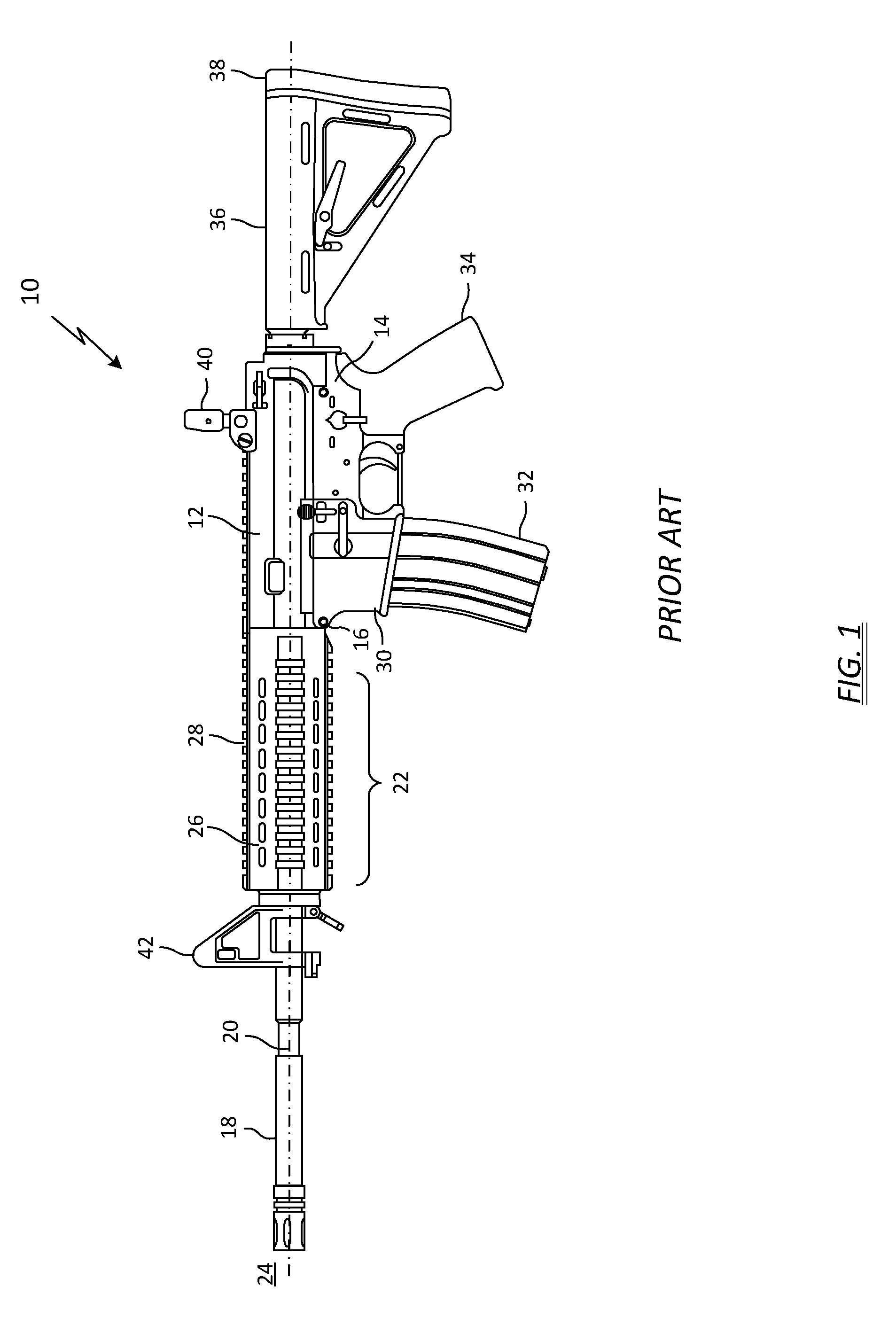
[0020] FIG. 1 depicts a prior art rifle;
[0021] FIG. 2 depicts a top perspective view of a firearm foregrip in accordance with one embodiment of the present invention;
[0022] FIG. 3 depicts an exploded view of the foregrip shown in FIG. 2;
[0023] FIG. 4 depicts an alternate top perspective view of the foregrip shown in FIG. 2;
[0024] FIG. 5 depicts a side view of the foregrip shown in FIG. 2;
[0025] FIG. 6 depicts a partially exploded bottom view of the foregrip shown in FIG. 2;
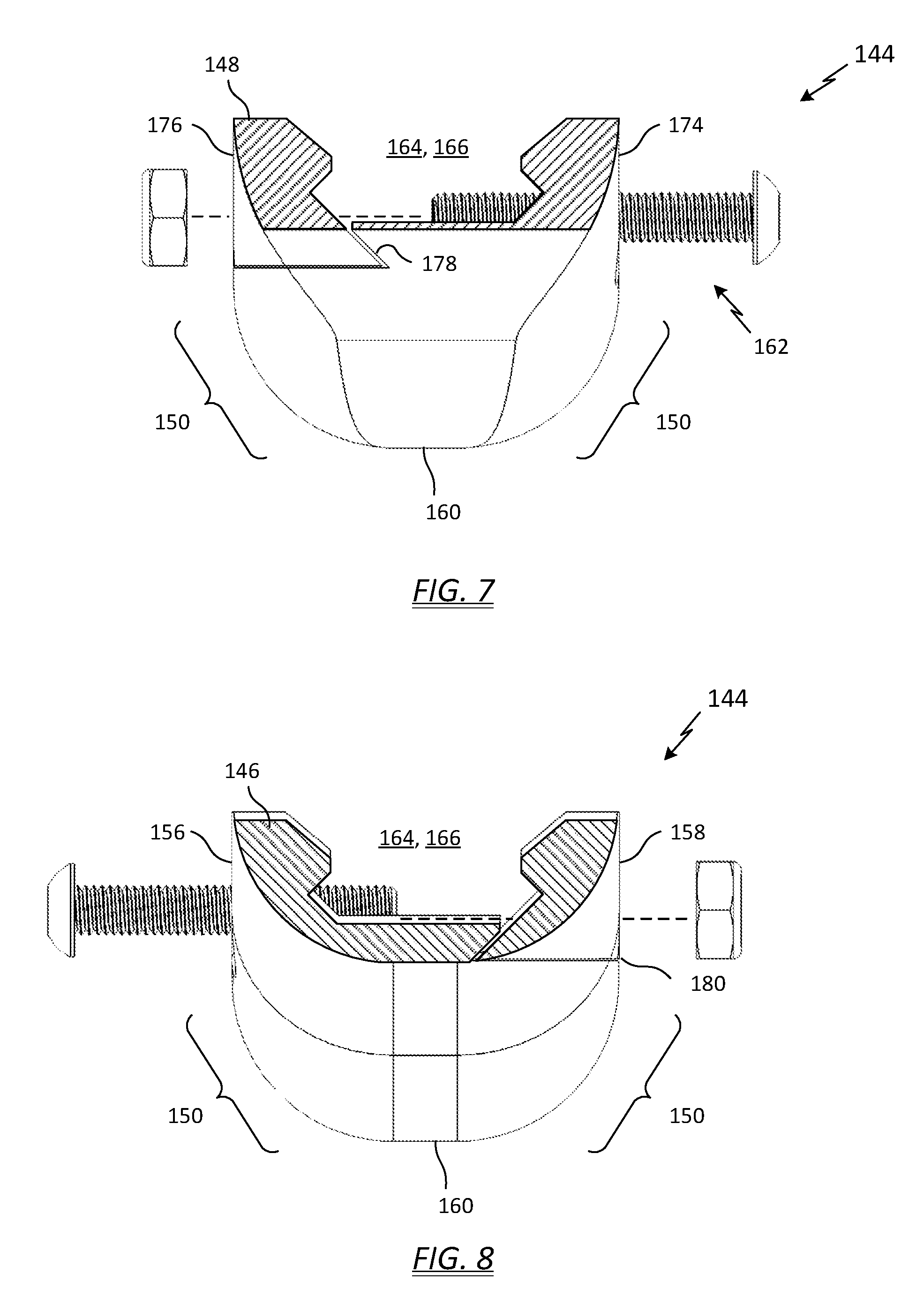
[0026] FIG. 7 depicts a partially exploded rear view of the foregrip shown in FIG. 6;
[0027] FIG. 8 depicts a partially exploded front view of the foregrip shown in FIG. 6;
[0028] FIG. 9 depicts a side plan view of the foregrip shown in FIG. 2 mounted on a rifle;
[0029] FIG. 10 depicts a side plan view of a foregrip mounted on a rifle in accordance with a second embodiment of the present invention;
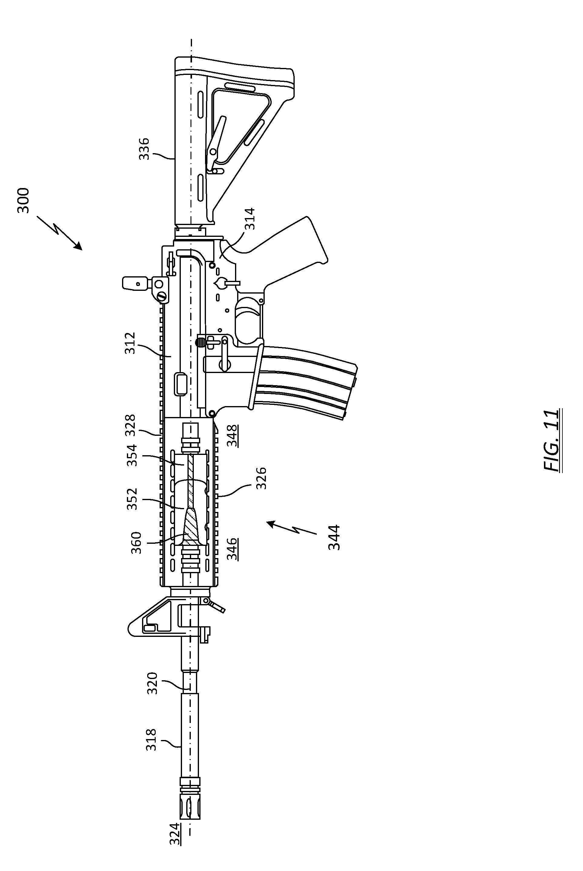
[0030] FIG. 11 depicts a side plan view of a foregrip mounted on a rifle in accordance with a third embodiment of the present invention;
[0031] FIG. 12 depicts a top perspective view of a firearm foregrip in accordance with a fourth embodiment of the present invention;
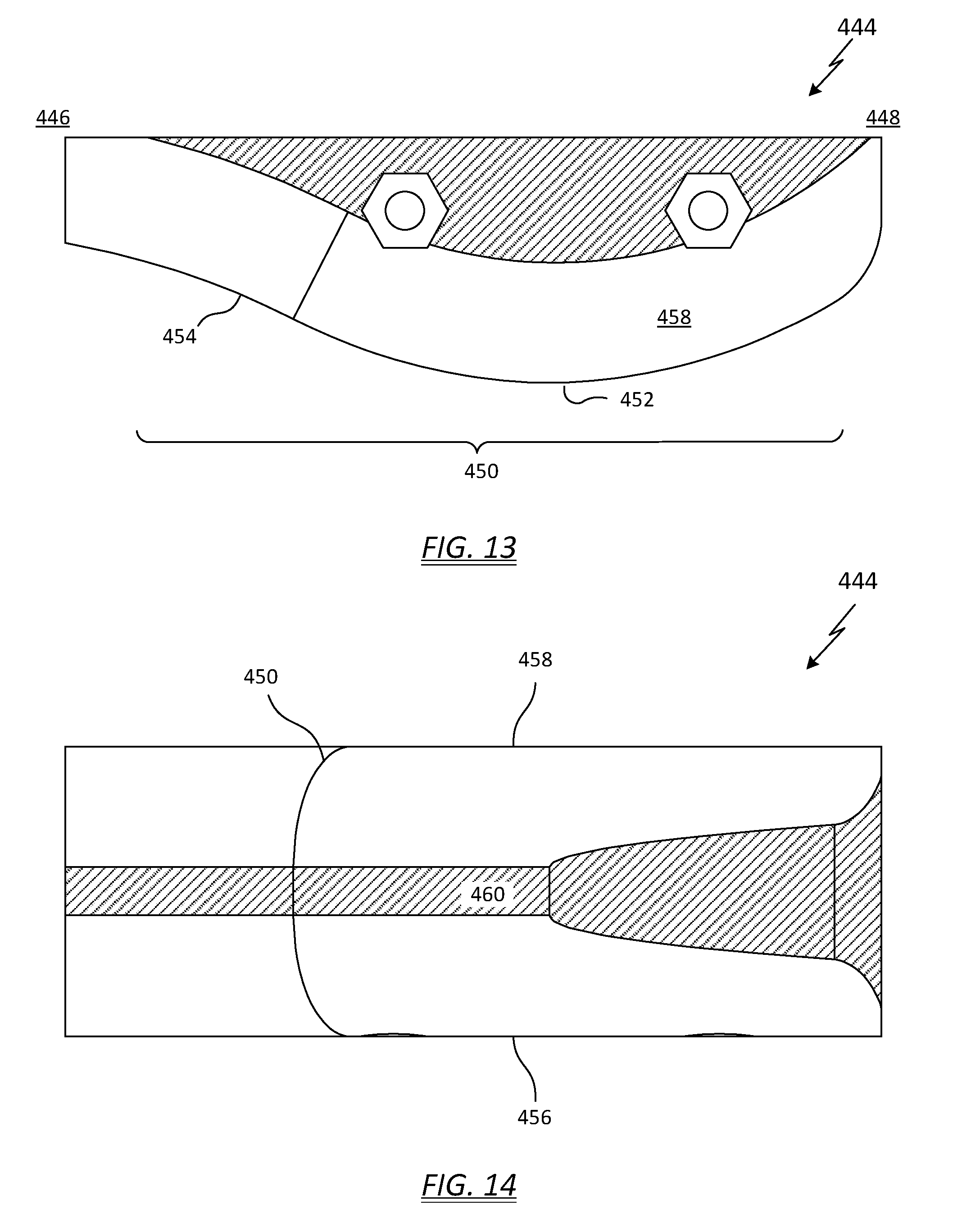
[0032] FIG. 13 depicts a side view of the foregrip shown in FIG. 12;
[0033] FIG. 14 depicts a bottom view of the foregrip shown in FIG. 12;
[0034] FIG. 15 depicts a rear view of the foregrip shown in FIG. 12;
[0035] FIG. 16 depicts a front view of the foregrip shown in FIG. 12;
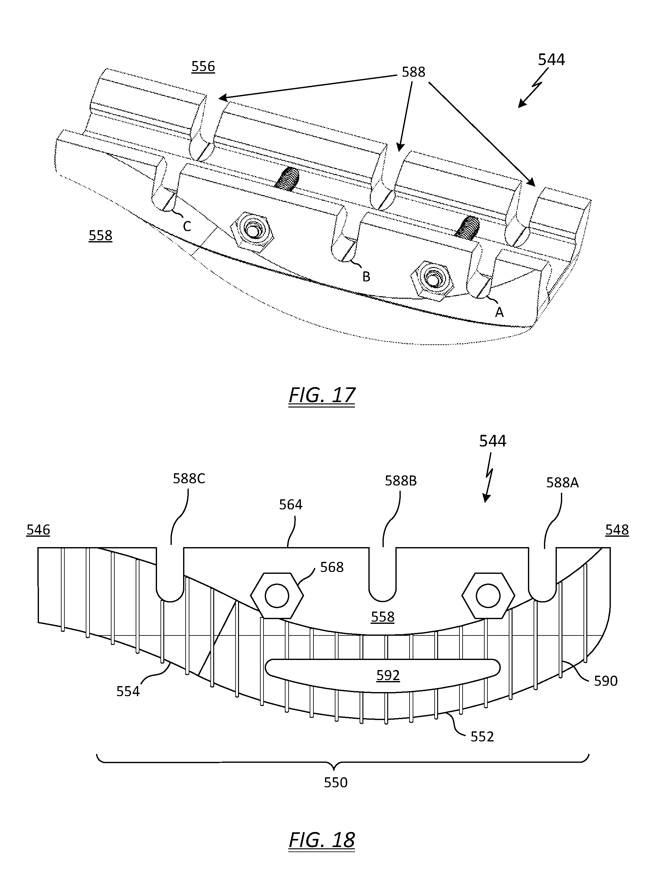
[0036] FIG. 17 depicts a top perspective view of a firearm foregrip in accordance with a fifth embodiment of the present invention;
[0037] FIG. 18 depicts a side view of the foregrip shown in FIG. 17; and
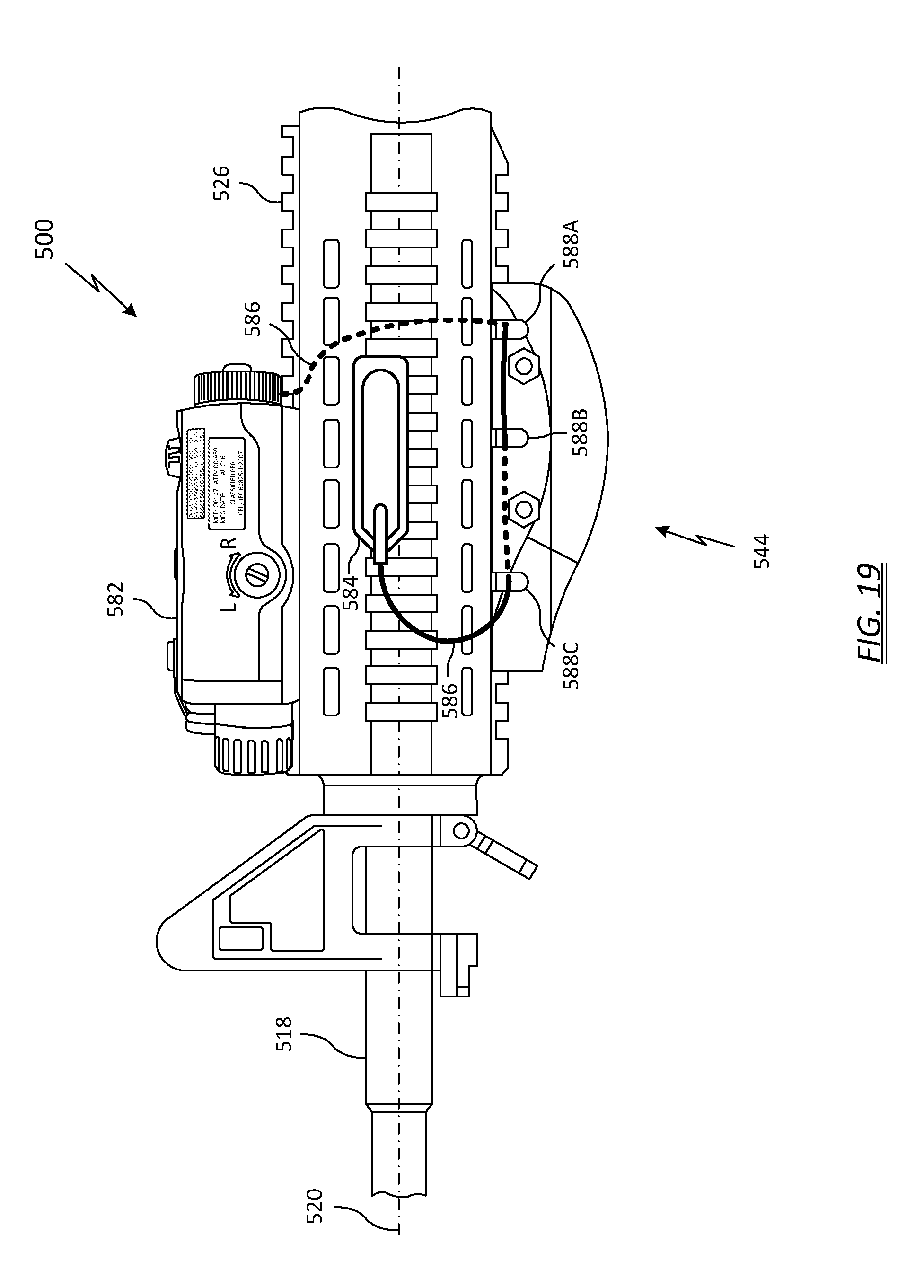
[0038] FIG. 19 depicts an enlarged side plan view of the foregrip shown in FIG. 17 mounted on a rifle.
DETAILED DESCRIPTION OF THE INVENTION
[0039] Referring to FIG. 1, a conventional rifle 10 such as an AR-15 includes a receiver portion comprising an upper receiver 12 pivotally connected to a lower receiver 14 at hinge 16. The upper receiver 12 includes a charging handle, forward assist, a gas operating system, a barrel 18, a bolt, and a bolt carrier assembly (not all elements shown). The barrel 18 extends longitudinally away from the upper receiver 12, defining a centerline axis 20. A forearm portion 22 located between the upper receiver 12 and the open end 24 of the barrel 18 provides a grip location for the off-hand. In the illustrated embodiment, an attachment rail 26, such as a Picatinny quad rail, provides a mounting platform on four sides of the barrel 18 (upper, lower, right, left) for attachable accessories. The Picatinny rail is a bracket made to military standards (MIL-STD-1913) having a dovetail shape along the barrel axis 20 with uniformly-spaced transverse slots 28. Firearm attachments with a corresponding dovetail slot can either slide down the attachment rail 26 or be assembled in two pieces, then tightened with screws.
[0040] The lower receiver 14 includes a magazine well 30, a detachable box magazine 32, a pistol grip 34, buttstock 36, buffer and buffer spring (not all elements shown). The buttstock 36 may include a butt plate 38 or similar component to provide a degree of added cushion where the stock braces against the shooter's shoulder. The lower receiver 14 also includes a trigger, disconnector, hammer, and fire selector (i.e., the fire control group).
[0041] The rifle 10 also includes a sighting mechanism, of which numerous variations are commercially available. In the illustrated embodiment, the sighting mechanism comprises an L-type flip rear sight 40 and post-type front sight 42. The front sight 42 is adjustable for elevation, and the rear sight 40 can be adjusted for wind.
[0042] Referring now to FIGS. 2-9, wherein like numerals indicate like elements in FIG. 1, shown is a rifle 100 having a foregrip 144 in accordance with one embodiment of the present invention. In the illustrated embodiment, the foregrip 144 is configured for assembly on the bottom side of the rifle barrel 118, but the invention is not so limiting and may include other orientations, as will be described in detail below. The foregrip 144 includes a forward portion 146 facing the open end 124 of the barrel 118, an opposing rear portion 148 facing the receiver 112, 114, and a curvilinear contact portion 150 extending from the forward portion 146 to the rear portion 148. By curvilinear, what is meant is that the surface is smooth and unbroken. The curvilinear contact portion 150 includes a convex portion 152 positioned towards the rear portion 148 of the foregrip 144, and a concave portion 154 positioned towards the forward portion 146 of the foregrip. The lateral sides of the foregrip 144, that is, right side 156 and left side 158, may also comprise a curvilinear surface. FIG. 7 and FIG. 8 illustrate one such example. The curvilinear contact portion 150 extends from the sides 156, 158 to a flat on the bottom surface 160. As shown in FIG. 6, depending upon the desired ergonomic fit, the flat 160 (shaded portion) may extend laterally (i.e., side-to-side), may vary in width along the barrel axis 120, and may extend from the forward portion 146 to the rear portion 148.
[0043] For a right-handed shooter the convex portion 152 of the curvilinear contact portion 150 is adapted to lie comfortably in the fleshy center or "meat" of the shooter's palm, with the thumb gripping the left side 158 of the foregrip 144, and the index, middle, ring, and little fingers wrapping around the bottom 160 and right side 156 of the foregrip 144, such that the middle portions of each finger wrap around the curvilinear contact portion 150 to the convex portion 152. By conforming to the shape of the shooter's palm, the foregrip 144 advantageously increases or even maximizes the hand's contact surface area with the firearm, thereby increasing comfort, reducing strain, and increasing firing accuracy.
[0044] The foregrip 144 can include a locking feature 162 configured to maintain the foregrip in a selected position relative to the attachment rail 126. An upper portion 164 of the foregrip can include a dovetail-shaped slot 166 along the barrel axis 120 for registration with the attachment rail 126. The foregrip 144 can slide axially along the attachment rail 126 on the underside of the barrel 118, then be secured at any location that is comfortable for the shooter. The locking feature 162 can include one or more fasteners 168, such as button-head socket cap screws, sized and configured to extend between lateral sides 156, 158 of the foregrip 144, with the shaft 170 of the cap screw being sized to be received between the slots 128 of the attachment rail 126. A locknut 172 tightened onto the cap screw 168 can both clamp the foregrip 144 to the attachment rail 126, and further to prevent movement of the foregrip along the length of the rail. Both the cap screw 168 and the locknut 172 may be black oxide coated to prevent corrosion and reduce glare.
[0045] The illustrated foregrip 144 comprises two pieces that nest over the attachment rail 126 so the foregrip does not need to be slipped on from the open end 124 of the barrel 118. A first piece 174 engages a lateral side and a bottom surface of the attachment rail 126, and a second, smaller piece 176 engages the opposing lateral side of the rail. In one embodiment, the mating surfaces 178 of the first and second pieces 174, 176 can be formed at complimentary angles to assure the surfaces are drawn towards each other as the locknut 172 is tightened. In one example, the angle can be 45 degrees.
[0046] The foregrip 144 can be formed from an injected molded thermal plastic such as hard urethane, Nylon or other polymeric materials. In one embodiment, the locknut 172 can be captured and held in the recessed cavity 179 formed in the left side 158 of the foregrip 144, in order to prevent the locknut from dropping out when the cap screw 168 is removed. In one example, a small nub can be formed into the cavity 179 during the molding process. While the mold is still warm and the nub is pliable, the locknut 172 can be pressed into the cavity 179, forming an interference fit with the nub. When the mold cools and hardens, the nut will be encapsulated.
[0047] In an alternate but not limiting method of manufacture, the foregrip 144 may be formed from a polymeric material using additive manufacturing techniques.
[0048] In one example, the foregrip 144 has an axial length (L) of approximately 4.25 inches, and a width (W) of approximately 1.5 inches. The curvilinear contact portion 150 can have a major height (H) of approximately 1.25 inches at the convex portion 152, with the convex surface having a radius of 3 inches. Further, the curvilinear contact portion 150 can have a minor height (h) of approximately 0.5 inches at the concave portion 154, with the concave surface having a radius of 4 inches. The lateral sides of the foregrip 144, that is, right side 156 and left side 158, may also comprise a curvilinear surface, having a radius of 0.625 inches.
[0049] FIG. 2 depicts a top perspective view of a first embodiment of a two-piece firearm foregrip 144. The shaded region illustrates a flat rear surface 148, as viewed from the left-side shooter's perspective looking down the barrel. The surface below the shaded region, extending towards the bottom, and the side surfaces 156, 158 are curvilinear. The foregrip 144 is shown with the fasteners 168 pre-assembled, as may be configured in retail packaging. The mating surfaces 178 between the first and second pieces 174, 176 can be seen pulled together.
[0050] FIG. 3 depicts an exploded view of the foregrip shown in FIG. 2, with the first piece 174 of the foregrip 144 being separated from the second piece 176. This configuration is representative of the foregrip 144 prior to being assembled onto the attachment rail 126. The locknuts 172 have been removed, and the cap screws 168 are shown partially removed from the first piece 174.
[0051] FIG. 4 depicts a top perspective view of the foregrip shown in FIG. 2, as viewed from the right-side shooter's perspective looking down the barrel. The shaded region illustrates the flat rear surface 148.
[0052] FIG. 5 depicts a left-side view 158 of the foregrip 144 shown in FIG. 2, with the convex portion 152 oriented toward the shooter. The shaded region illustrates a flat portion on the left side 158 (and the right side 156, not shown). The flat portion is primarily in the region of the locking feature 162. The upper portion 164 (FIG. 7) of the foregrip is configured to attach to a bottom Picatinny rail 126, as shown in FIG. 9. A mating line 180 depicts the plane in which the bottom of the second piece 176 mates with the top of the first piece 174. In the side view, the mating line 180 can be seen as a horizontal line. Also clearly illustrated is the curvilinear contact portion 150 of the foregrip 144, having a smooth, unbroken curvature extending from the forward portion 146 to the rear portion 148.
[0053] FIG. 6 depicts a bottom view 160 of the foregrip 144 shown in FIG. 2. The shaded region illustrates an optional flat surface on the bottom, which may provide a surer grip in the palm of the hand. The locking feature 162 is shown in partially exploded view for clarity.
[0054] FIG. 7 and FIG. 8 depict a rear view 148 and a front view 146, respectively, of the foregrip 144. The shaded regions illustrate the flat surfaces at either end. The upper portion 164 of the foregrip defines the dovetail-shaped slot 166 for registration with the Picatinny rail 126. Also clearly shown are the mating surfaces 178 and mating line 180 between the first piece 174 and second piece 176. The locking feature 162 is shown in partially exploded view for clarity.
[0055] FIG. 9 depicts a side view of a rifle 100 with attached foregrip 144 in accordance with the first embodiment of the invention. In one example, the rifle 100 can be the AR-15 with quad rail 26 shown in FIG. 1. The foregrip 144 is secured to the bottom attachment rail 126 of the rifle 100. The convex portion 152 of the foregrip is positioned at the rear portion 148 of the foregrip 144, and the concave portion 154 is positioned at the forward portion 146 of the foregrip.
[0056] One advantage of the disclosed foregrip 144 is that, due to its smooth, curvilinear contact portion 150, it can be reoriented if the user so desires to customize the fit or grip in the shooter's palm. As noted above, the foregrip 144 can be positioned forward or aft along the attachment rail 126 to provide the best personalized fit for the shooter. For example, a shooter with a smaller-sized palm may desire the foregrip 144 positioned more rearward, so their palm substantially contacts that portion of the curvilinear contact surface 150 between the major height (H) and minor height (h), or even just the minor height (h) (FIG. 5).
[0057] Other reoriented configurations are possible within the scope of the invention. Referring to FIG. 10, wherein like numerals indicate like elements in FIGS. 2-9, shown is a side plan view of a foregrip 244 mounted on a rifle 200 in accordance with a second embodiment of the present invention. Here, the orientation is reversed relative to the first embodiment. As such, the curvilinear contact portion 250 of the foregrip 244 still extends from the forward portion 246 to the rear portion 248, but in this embodiment the concave portion 254 is positioned towards the rear portion 248 of the foregrip 244, and the convex portion 252 is positioned towards the forward portion 246 of the foregrip 244. Shooters with large hands may prefer this orientation, such that their fingers wrap around substantially the convex portion 252 of the foregrip 244. Alternatively, shooters with smaller-sized hands may prefer to wrap their fingers around substantially the concave portion 254 of the foregrip 244.
[0058] Turning now to FIG. 11, wherein like numerals indicate like elements in FIGS. 2-9, shown is a side plan view of a foregrip 344 mounted on a rifle 300 in accordance with a third embodiment of the present invention. Here, the foregrip 344 is mounted to the left side attachment rail 326, that is, to the rail secured to the side of the firearm barrel 318, not underneath the barrel as previously disclosed. Thus, the view depicted in FIG. 11 is looking at the bottom 360 surface of the foregrip 344. In the illustrated embodiment, the convex portion 352 of the curvilinear contact surface 350 is positioned towards the forward portion 346 of the foregrip 344, and the concave portion 354 is positioned towards the rear portion 348 of the foregrip. This configuration may be preferable for shooters who grip the barrel 318 in a "C-clamp," positioning their thumb on top of the barrel 318, at approximately the 11 o'clock position (for a right-handed shooter). Of course, some shooters may prefer to reverse the orientation, and such configuration is contemplated within the scope of the invention.
[0059] Turning now to FIGS. 12-16, shown is a firearm foregrip 444 in accordance with a fourth embodiment of the present invention. The foregrip 444 comprises a one-piece construction, which may be beneficial for reducing manufacturing costs. The foregrip 444 can be formed from an injected molded thermal plastic such as hard urethane, Nylon or other polymeric materials. Alternatively, but not limiting, the foregrip 444 may be formed from a polymeric material using additive manufacturing techniques.
[0060] The foregrip 444 includes a forward portion 446 configured to face toward the open end 424 of the barrel 418, and an opposing rear portion 448 facing the upper receiver 412 of the rifle 400. The foregrip 444 further includes curvilinear contact portion 450 extending from the forward portion 446 to the rear portion 448. By curvilinear, what is meant is that the surface is smooth and unbroken. The curvilinear contact portion 450 includes a convex portion 452 positioned towards the rear portion 448 of the foregrip 444, and a concave portion 454 positioned towards the forward portion 446 of the foregrip. The lateral sides of the foregrip 444, that is, right side 456 and left side 458, may also comprise a curvilinear surface.
[0061] The foregrip 444 can include a locking feature 462 (not illustrated) configured to maintain the foregrip in a selected position relative to the attachment rail 426. An upper portion 464 of the foregrip can include a dovetail-shaped slot 466 along the barrel axis 420 for registration with the attachment rail 426. The foregrip 444 can slide axially along the attachment rail 426 on the underside of the barrel 418, or any other side of the barrel 418 having an attachment rail 426, then be secured at any axial location that is comfortable for the shooter. The locking feature 462 can include one or more fasteners 468, such as button-head socket cap screws, sized and configured to extend between lateral sides 456, 458 of the foregrip 444, with the shaft 470 of the cap screw being sized to be received between the slots 428 of the attachment rail 426. A locknut 472 tightened onto the cap screw 468 can both clamp the foregrip 444 to the attachment rail 426, and further to prevent movement of the foregrip along the length of the rail.
[0062] Dimensionally, the foregrip 444 can be sized substantially the same as the foregrip disclosed with reference to FIG. 2.
[0063] FIG. 13 depicts a left-side view 458 of the foregrip 444 shown in FIG. 12, with the convex portion 452 oriented toward the shooter. The shaded region illustrates a flat portion on the left side 458 (and the right side 456, not shown). The flat portion is primarily in the region of the locking feature 462. The upper portion 464 of the foregrip is configured to attach to a bottom Picatinny rail 426, as shown in FIG. 9. Clearly illustrated is the curvilinear contact portion 450 of the foregrip 444, having a smooth, unbroken curvature extending from the forward portion 446 to the rear portion 448.
[0064] FIG. 14 depicts a bottom view 460 of the foregrip 444 shown in FIG. 12. The shaded region illustrates an optional flat surface on the bottom, which may provide a surer grip in the palm of the hand. FIG. 15 and FIG. 16 depict a rear view 448 and a front view 446, respectively, of the one-piece foregrip 444. The shaded regions illustrate the flat surfaces at either end. The upper portion 464 of the foregrip defines the dovetail-shaped slot 466 for registration with the Picatinny rail 426.
[0065] FIGS. 17-19 depict a firearm foregrip 544 in accordance with a fifth embodiment of the present invention. In the illustrated embodiment, the foregrip 544 is a two-piece configuration, but can also comprise a one-piece construction. Referring to FIG. 18, a foregrip 544 may include a plurality of raised ribs 590 to provide better grip. In one example, the ribs 590 extend transversely across the curvilinear contact portion 550, are equally spaced and semi-circular in cross-section, having a radius of approximately 0.030 inches. The lower portion of the foregrip 544 may define a through-cavity 592 oriented transverse to the barrel axis to reduce weight and simplify molding operations. In the illustrated embodiment, the through-cavity 592 extends axially approximately the distance of the spacing between the fasteners 568. The bottom surface of the through-cavity 592 may follow the contour of the curvilinear contact portion 550, and the upper surface may be flat.
[0066] FIG. 19 shows the rifle 500 having a specialized device secured on the attachment rail 526, namely, an Advanced Target Pointer/Illuminator Aiming Laser (ATPIAL) 582. The ATPIAL 582 can include an infrared laser pointer, a (red) visible laser pointer, and an infrared laser illuminator. The infrared laser pointer and the visible laser pointer emit a narrow beam to assist in aiming the rifle 500, and the infrared laser illuminator emits a wide beam to illuminate a target. The infrared laser pointer and infrared laser illuminator are used with night vision goggles. Typically, an ATPIAL 582 includes a button on top of the device to activate the lasers. However, many shooters prefer an optional pressure switch 584 that plugs into the rear of the device via cord 586. Pressing the pressure switch 584 accomplishes the same function as pressing the button. The pressure switch 584 may be placed in any location comfortable for the shooter, such that the lasers may be activated without removing the off-hand from the foregrip 544.
[0067] The cord 586 connecting the pressure switch 584 to the ATPIAL 582 is typically one to two feet in length, which can result in a length of excess cord. The excess cord is typically wrapped around the attachment rail 526 to keep it out of the way. However, this method presents a problem with a rifle having the disclosed foregrip 544: the cord 586 would wrap over the grip, which could interfere with the off-hand grasp of the foregrip 544.
[0068] To alleviate this problem, returning to FIGS. 17-19, the foregrip 544 may define one or more through-passageways 588 extending from the right side 556 of the foregrip 544 to the left side 558. In the illustrated embodiment, the through-passageways 588 comprise slots formed into the upper portion 564 of the foregrip 544, running transverse, or at a right angle to, the axis 520 of the barrel 518. However, in other examples, the through-passageways 588 can be at some other angle relative to the axis 520. The through-passageways 588 may be configured for passage of the pressure switch cord 586. In one example, the through-passageway 588 may comprise three slots (A, B, C) approximately 0.20 inches wide and 0.40 inches deep.
[0069] As shown in FIG. 19, where the dashed lines indicate the cord 586 is positioned on the opposite side of the rifle 500, the cord plugs into the rear of the ATPIAL 582, passes down the opposite side of the attachment rail 526 and through slot 588A, then forward and through slot 588B, around the back side of the foregrip 544, and through slot 588C. The pressure switch 584 can be secured to the attachment rail 526 at the desired location using hook and loop fasteners, for example. In this manner, the shooter can activate the laser sights with finger pressure while not having to remove their off-hand from the foregrip 544.
[0070] One of the improvements of the disclosed foregrip is that the curvilinear contact surface is responsive to the noted problem of a shooter having to change grip when advancing between standing, crouching, and prone shooting positions. The concave portion lies comfortably in the shooter's palm, and remains so when changing shooting position. Even though the off-hand wrist rotates, the curvilinear contact surface remains nested in the palm, which provides greater contact surface area with the firearm than conventional attachments or hand guards.
[0071] Embodiments of the present invention can be adapted to most any firearm with an attachment rail, notably the M4 carbine, M16, AR-10, and like semi-automatic rifles. Furthermore, other embodiments the foregrip may be adapted to firearms without an attachment rail, such as a shotgun and standard rifle. In one example, the foregrip can be integral with the barrel, or integral with a molded forearm portion of a rifle.
[0072] While the present invention has been described with reference to a number of specific embodiments, it will be understood that the true spirit and scope of the invention should be determined only with respect to claims that can be supported by the present specification. Further, while in numerous cases herein wherein systems and apparatuses and methods are described as having a certain number of elements it will be understood that such systems, apparatuses and methods can be practiced with fewer than the mentioned certain number of elements. Also, while a number of particular embodiments have been described, it will be understood that features and aspects that have been described with reference to each particular embodiment can be used with each remaining particularly described embodiment.
* * * * *
D00000
D00001
D00002
D00003
D00004
D00005
D00006
D00007
D00008
D00009
D00010
D00011
D00012

D00013
D00014
XML
uspto.report is an independent third-party trademark research tool that is not affiliated, endorsed, or sponsored by the United States Patent and Trademark Office (USPTO) or any other governmental organization. The information provided by uspto.report is based on publicly available data at the time of writing and is intended for informational purposes only.
While we strive to provide accurate and up-to-date information, we do not guarantee the accuracy, completeness, reliability, or suitability of the information displayed on this site. The use of this site is at your own risk. Any reliance you place on such information is therefore strictly at your own risk.
All official trademark data, including owner information, should be verified by visiting the official USPTO website at www.uspto.gov. This site is not intended to replace professional legal advice and should not be used as a substitute for consulting with a legal professional who is knowledgeable about trademark law.