Flat Heat Pipe With Composite Wick Material
TSENG; Chuan-Chi ; et al.
U.S. patent application number 15/924013 was filed with the patent office on 2019-08-08 for flat heat pipe with composite wick material. The applicant listed for this patent is TAI-SOL ELECTRONICS CO., LTD.. Invention is credited to Yueh-Lung CHUANG, Chuan-Chi TSENG, Yong-Zhen WANG, Xiao-Long WU.
| Application Number | 20190242655 15/924013 |
| Document ID | / |
| Family ID | 62186633 |
| Filed Date | 2019-08-08 |


| United States Patent Application | 20190242655 |
| Kind Code | A1 |
| TSENG; Chuan-Chi ; et al. | August 8, 2019 |
FLAT HEAT PIPE WITH COMPOSITE WICK MATERIAL
Abstract
A flat heat pipe with composite wick material includes: a flat pipe; a pipe-wall wick structure disposed on an inner wall of the pipe and extending in an axial direction of the pipe, wherein, from a perspective of its cross section, the pipe has an upper inner wall and left and right arcuate inner walls, an opening facing downward, and a lower inner wall not being completely covered; a fiber bundle disposed at the opening formed at the pipe-wall wick structure; and a working fluid disposed in the pipe. One of two contact surfaces of the fiber bundle is coupled to the lower inner wall of the pipe by sintering. The other contact surface of the fiber bundle is in contact with the pipe-wall wick structure.
| Inventors: | TSENG; Chuan-Chi; (TAIPEI CITY, TW) ; CHUANG; Yueh-Lung; (TAIPEI CITY, TW) ; WU; Xiao-Long; (WUJIANG CITY, TW) ; WANG; Yong-Zhen; (WUJIANG CITY, TW) | ||||||||||
| Applicant: |
|
||||||||||
|---|---|---|---|---|---|---|---|---|---|---|---|
| Family ID: | 62186633 | ||||||||||
| Appl. No.: | 15/924013 | ||||||||||
| Filed: | March 16, 2018 |
| Current U.S. Class: | 1/1 |
| Current CPC Class: | F28D 15/0233 20130101; F28F 19/00 20130101; F28D 15/046 20130101 |
| International Class: | F28D 15/04 20060101 F28D015/04; F28D 15/02 20060101 F28D015/02 |
Foreign Application Data
| Date | Code | Application Number |
|---|---|---|
| Feb 5, 2018 | TW | 107201762 |
Claims
1. A flat heat pipe with composite wick material, comprising: a pipe being flat, having two closed ends, being defined from an end thereof to another end thereof with a heating segment, a thermal insulation segment and a condensation segment, and having a cross section with flat upper and lower sides and arcuate left and right sides; a pipe-wall wick structure disposed on an inner wall of the pipe and extending in an axial direction of the pipe, wherein, from a perspective of its cross section, the pipe has an upper inner wall being covered, an opening facing downward, and a lower inner wall not being completely covered, and, at the very least, the pipe-wall wick structure is disposed at the heating segment of the pipe; a fiber bundle comprising a plurality of fibers, being flat and slender, having two opposing contact surfaces, being disposed in the pipe and at the opening formed at the pipe-wall wick structure, extending along a long axis of the pipe, and thus being disposed at the heating segment, the thermal insulation segment and the condensation segment, wherein a portion of an internal space of the pipe is occupied by the fiber bundle; and a working fluid disposed in the pipe, wherein one of the contact surfaces of the fiber bundle is coupled to the lower inner wall of the pipe by sintering, and the other contact surface of the fiber bundle is in contact with the pipe-wall wick structure.
2. The flat heat pipe with composite wick material according to claim 1, wherein, from the perspective of the cross section, two edges of the pipe-wall wick structure are in contact with the fiber bundle.
3. The flat heat pipe with composite wick material according to claim 1, wherein, from the perspective of the cross section, an edge of the pipe-wall wick structure is in contact with the fiber bundle, but another edge of the pipe-wall wick structure is not in contact with the fiber bundle.
4. The flat heat pipe with composite wick material according to claim 1, wherein, from the perspective of the cross section, two edges of the pipe-wall wick structure are not in contact with the fiber bundle.
5. The flat heat pipe with composite wick material according to claim 1, wherein the pipe-wall wick structure is one of a mesh wick structure and a sintered copper powder wick structure.
6. The flat heat pipe with composite wick material according to claim 1, wherein, from the perspective of the axial direction of the pipe, the pipe-wall wick structure is disposed at the heating segment of the pipe in whole and at the thermal insulation segment of the pipe in part, whereas a portion belonging to the fiber bundle and extending beyond the pipe-wall wick structure has its two contact surfaces coupled to the upper and lower inner walls of the pipe by sintering.
7. The flat heat pipe with composite wick material according to claim 1, wherein, from the perspective of the axial direction of the pipe, the pipe-wall wick structure is disposed at the heating segment of the pipe in whole and at the thermal insulation segment of the pipe in whole, whereas a portion belonging to the fiber bundle and extending beyond the pipe-wall wick structure has its two contact surfaces coupled to the upper and lower inner walls of the pipe by sintering.
8. The flat heat pipe with composite wick material according to claim 1, wherein, from the perspective of the axial direction of the pipe, the pipe-wall wick structure is disposed at the heating segment, the thermal insulation segment and the condensation segment of the pipe in whole.
9. The flat heat pipe with composite wick material according to claim 1, wherein, from the perspective of the cross section, the pipe-wall wick structure not only covers the upper inner wall of the pipe but also covers the left and right arcuate inner walls of the pipe
Description
BACKGROUND OF THE INVENTION
Technical Field
[0001] The present invention relates to heat pipes and, more particularly, to a flat heat pipe with composite wick material.
2. Description of Related Art
[0002] China patent CN 201787845 U discloses a flat heat pipe with a composite wick structure. The flat heat pipe includes a pipe and a triple wick structure therein. The triple wick structure includes a grooved wick, a porous wick and a fibrous wick. The flat heat pipe will function well, unless it is flattened and bent. However, after the flat heat pipe has been flattened and bent, the porous wick is likely to undergo structural collapse at the site of the bend and the flattening. Owing to the structural collapse, the triple wick structure works much worse or even fails, leading to poor circulation of a working fluid therein. The collapsed wick structure occupies space otherwise available for passage of a gaseous working fluid; hence, the gaseous working fluid spreads so badly as to deteriorate the overall performance of heat transfer or uniform temperature distribution.
[0003] Taiwan patent TW M521170 discloses a heat pipe with a fibrous wick structure. The heat pipe overcomes the aforesaid flattening-and-bending-induced drawback of the conventional heat pipe, because it has therein a wick structure rendered firm and noncollapsible by sintering a fibrous wick structure and a mesh wick structure in a pipe. However, with the fibrous wick structure not being sintered to the heat pipe pipe-wall directly (because the fibrous wick structure is sintered to the mesh wick structure, and the mesh wick structure is sintered to the heat pipe pipe-wall,) the fibrous wick structure is likely to be torn off the mesh wick structure under a great force associated with deformation caused by the flattening and bending of the heat pipe, thereby opening to the chance of wick structure collapse and the subsequent occupation of internal space by the collapsed wick structure.
BRIEF SUMMARY OF THE INVENTION
[0004] As mentioned before, there is a drawback of the prior art, that is, after a conventional heat pipe has been flattened and bent, a wick structure therein undergoes structural collapse and thus works much worse or even fails. In view of this, the present invention aims to overcome the drawback.
[0005] It is an objective of the present invention to provide a flat heat pipe with composite wick material whereby a wick structure in the flat heat pipe is firmly fixed in place and thus is less likely to collapse even after the flat heat pipe has been flattened and bent.
[0006] Therefore, a flat heat pipe with composite wick material provided according to the present invention comprises: a pipe being flat, having two closed ends, being defined from an end thereof to another end thereof with a heating segment, a thermal insulation segment and a condensation segment, and having a cross section with flat upper and lower sides and arcuate left and right sides; a pipe-wall wick structure disposed on an inner wall of the pipe and extending in an axial direction of the pipe, wherein, from a perspective of its cross section, the pipe has an upper inner wall, left and right arcuate inner walls, an opening facing downward, and a lower inner wall not covering the pipe completely, and, at the very least, the pipe-wall wick structure is disposed at the heating segment of the pipe; a fiber bundle comprising a plurality of fibers, being flat and slender, having two opposing contact surfaces, being disposed in the pipe and at the opening formed at the pipe-wall wick structure, extending along a long axis of the pipe, and thus being disposed at the heating segment, the thermal insulation segment and the condensation segment, wherein a portion of an internal space of the pipe is occupied by the fiber bundle; and a working fluid disposed in the pipe, wherein one of the contact surfaces of the fiber bundle is coupled to the lower inner wall of the pipe by sintering, and the other contact surface of the fiber bundle is in contact with the pipe-wall wick structure.
[0007] With the fiber bundle being disposed at the opening formed at the pipe-wall wick structure and thus the fiber bundle being coupled directly to the inner walls of the pipe by sintering, the wick structure inside the pipe is firmly fixed in place and thus does not collapse even after the flat heat pipe has been flattened and bent, thereby overcoming the drawbacks of the prior art.
BRIEF DESCRIPTION OF THE SEVERAL VIEWS OF THE DRAWINGS
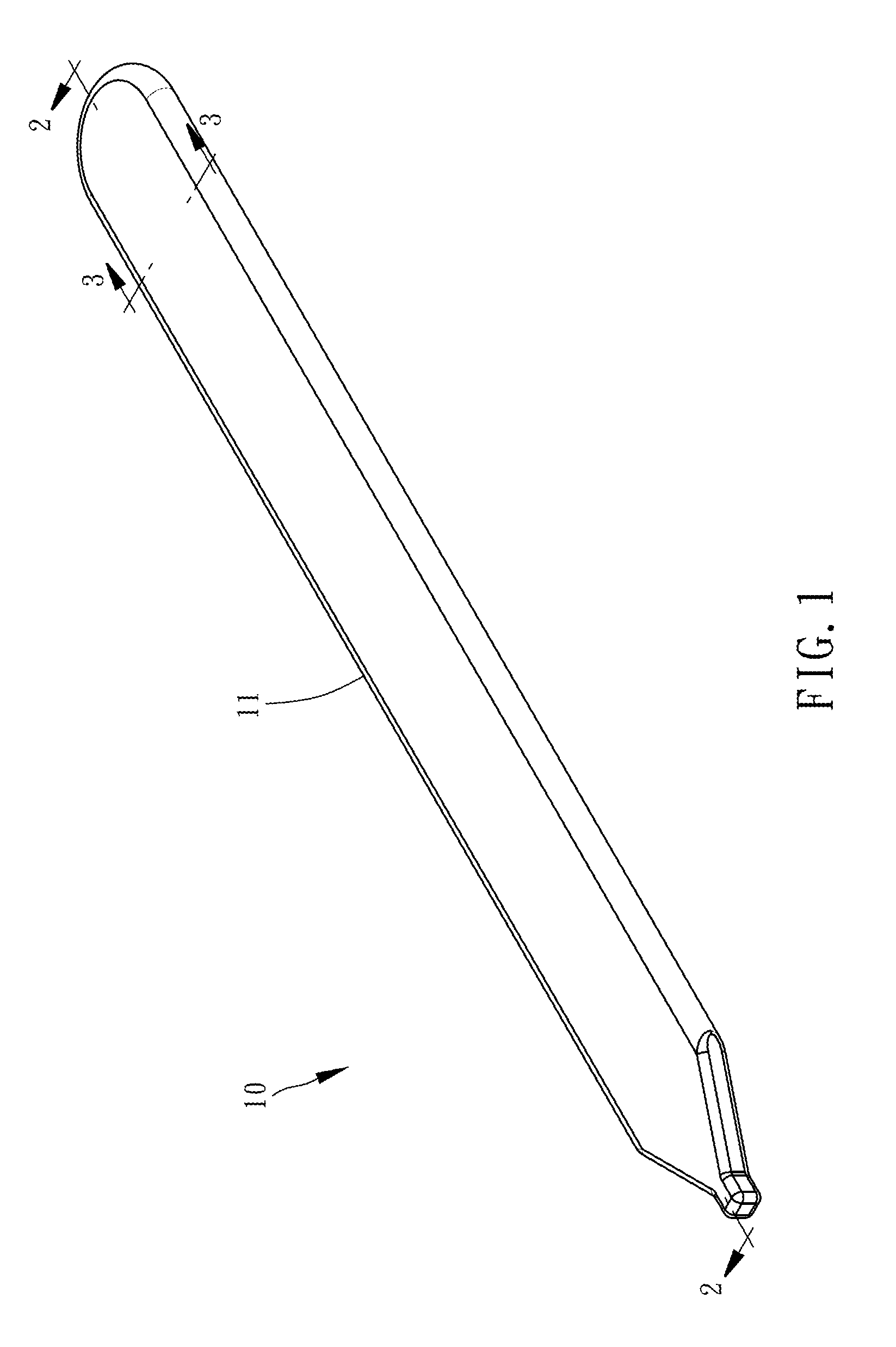
[0008] FIG. 1 is a perspective view of a flat heat pipe according to the first preferred embodiment of the present invention;
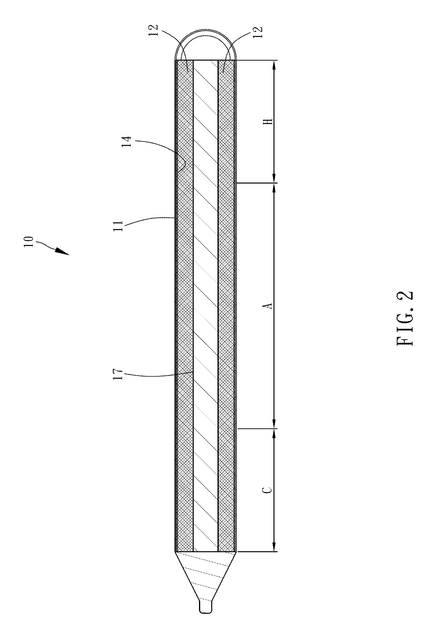
[0009] FIG. 2 is a cross-sectional view of the flat heat pipe taken along line 2-2 of FIG. 1;
[0010] FIG. 3 is a cross-sectional view of the flat heat pipe taken along line 3-3 of FIG. 1;
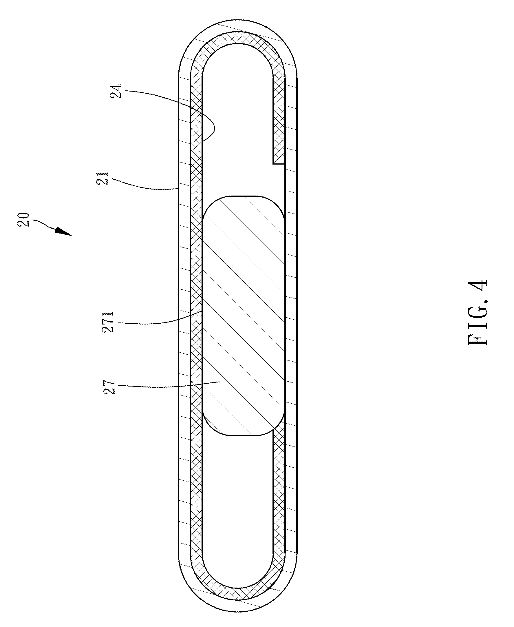
[0011] FIG. 4 is a cross-sectional view of the flat heat pipe according to the second preferred embodiment of the present invention;
[0012] FIG. 5 is a cross-sectional view of the flat heat pipe according to the third preferred embodiment of the present invention;
[0013] FIG. 6, which is similar to FIG. 2, is a longitudinal cross-sectional view of the flat heat pipe of the present invention;
[0014] FIG. 7, which is similar to FIG. 2, is another longitudinal cross-sectional view of the flat heat pipe of the present invention; and
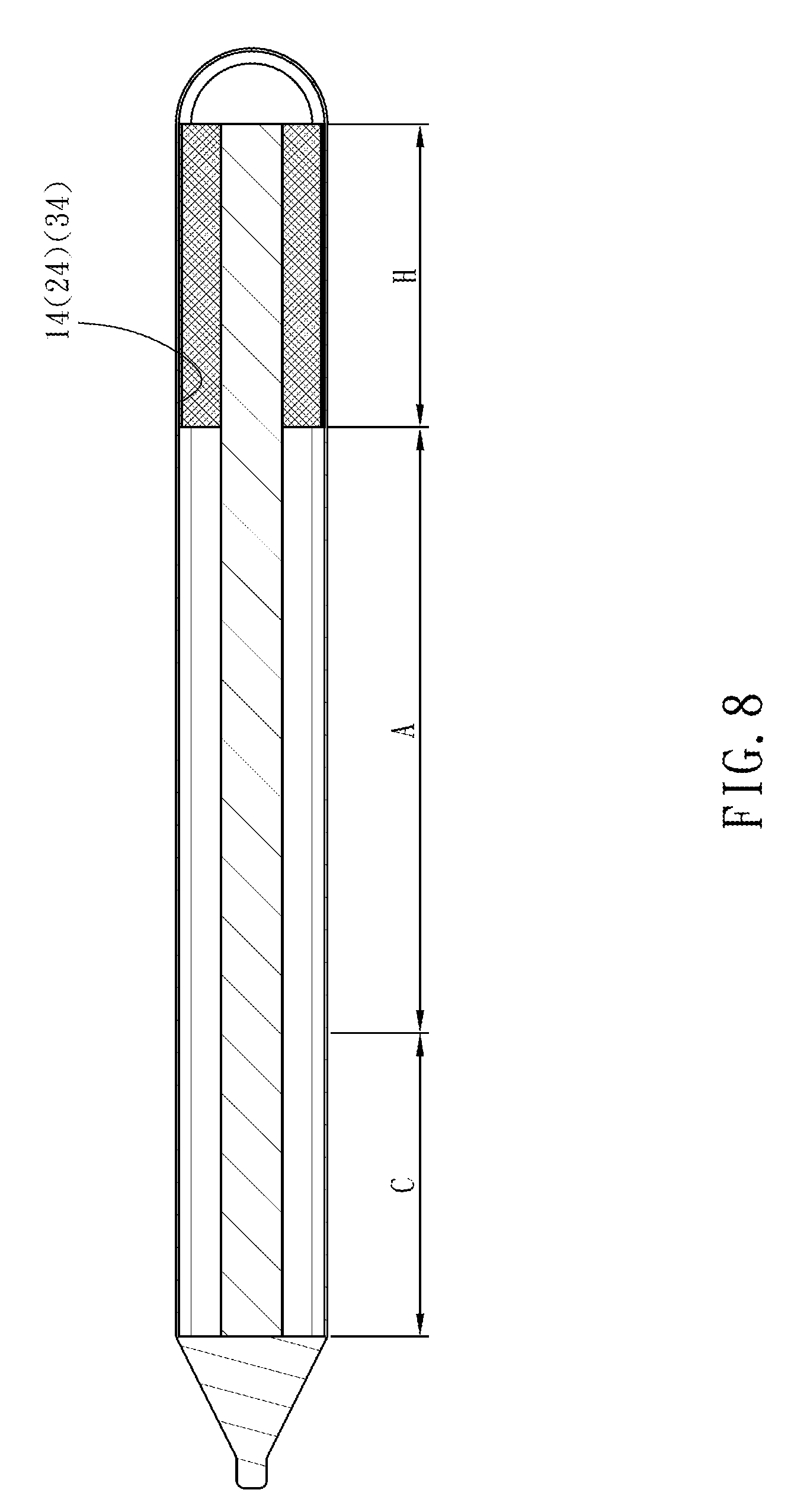
[0015] FIG. 8, which is similar to FIG. 2, is yet another longitudinal cross-sectional view of the flat heat pipe of the present invention.
DETAILED DESCRIPTION OF THE INVENTION
[0016] To explain the technical features of the present invention, the present invention is hereunder illustrated by preferred embodiments and drawings.
[0017] Referring to FIG. 1 through FIG. 3, a flat heat pipe 10 with composite wick material provided in the first preferred embodiment of the present invention essentially comprises a pipe 11, a pipe-wall wick structure 14, a fiber bundle 17 and a working fluid.
[0018] The pipe 11 is flat and has two closed ends. The pipe 11 is, from one end to the other end, defined with a heating segment H, a thermal insulation segment A and a condensation segment C. In this embodiment, the heating segment H and the condensation segment C are disposed at the two ends of the pipe 11, respectively. The cross section of the pipe 11 has flat upper and lower sides as well as arcuate left and right sides.
[0019] The pipe-wall wick structure 14 is disposed on an inner wall of the pipe 11 and extends in the axial direction of the pipe 11. From the perspective of its cross section, the pipe 11 has: an upper inner wall as well as left and right arcuate inner walls (with reference to the direction shown in FIG. 3) which are covered; an opening 15 which faces downward; and a lower inner wall which is incompletely covered. At the very least, the pipe-wall wick structure 14 is disposed at the heating segment H of the pipe 11. In the first embodiment, the pipe-wall wick structure 14 is disposed at the heating segment H, the thermal insulation segment A and the condensation segment C of the pipe 11 in whole. The pipe-wall wick structure 14 is selectively a mesh wick structure or a sintered copper powder wick structure. The flat heat pipe 10 with composite wick material according to the present invention is exemplified by a mesh wick structure for the sake of illustration.
[0020] The fiber bundle 17 comprises a plurality of fibers. The fiber bundle 17 is flat and slender. The fiber bundle 17 has two opposing contact surfaces 171. The fiber bundle 17 is disposed in the pipe 11 and at the opening 15 formed at the pipe-wall wick structure 14. The fiber bundle 17 extends along the long axis of the pipe 11 and thus is disposed at the heating segment H, the thermal insulation segment A and the condensation segment C. A portion of the internal space of the pipe 11 is occupied by the fiber bundle 17, and thus the internal space of the pipe 11 is divided into two sub-spaces 12. In the first embodiment, from the perspective of the cross section, two edges of the pipe-wall wick structure 14 are in contact with the fiber bundle 17.
[0021] The working fluid is disposed in the pipe 11. The working fluid is adsorbed into the fiber bundle 17 and the pipe-wall wick structure 14 and thus cannot be shown in the diagrams. Since the working fluid is a conventional component well-known in the field of heat pipes, it is not shown in the diagrams.
[0022] One of the contact surfaces 171 of the fiber bundle 17 is coupled to the lower inner wall of the pipe 11 by sintering. The other contact surface 171 of the fiber bundle 17 is in contact with the pipe-wall wick structure 14.
[0023] The structure of the flat heat pipe with composite wick material in the first embodiment is described above. The operation of the flat heat pipe with composite wick material in the first embodiment is described below.
[0024] Referring to FIG. 1 through FIG. 3, the heating segment H of the pipe 11 is in contact with a heat source (not shown) to receive heat generated from the heat source. Hence, the working fluid disposed at the heating segment H is heated up and evaporated into a gaseous working fluid. Then, the gaseous working fluid spreads to the condensation segment C through the two sub-spaces 12. With the condensation segment C not being supplied with heat from any other heat source, the gaseous working fluid cools down and condenses into a liquid working fluid. Afterward, the liquid working fluid permeates the pipe-wall wick structure 14 and the fiber bundle 17 and then returns, by capillarity, to the heating segment H quickly. Upon its arrival at the heating segment H, the liquid working fluid is heated up and evaporated into the gaseous working fluid again. The aforesaid cycle repeats, thereby achieving quick heat transfer and uniform temperature distribution. From the perspective of the cross section, the two edges of the pipe-wall wick structure 14 are in contact with the fiber bundle 17 whose upper contact surface 171 is also in contact with the pipe-wall wick structure 14, and the liquid working fluid flows within the fiber bundle 17 faster than within the pipe-wall wick structure 14; hence, the returning liquid working fluid tends to flow from the fiber bundle 17 to the pipe-wall wick structure 14 via the aforesaid points of contact, and thus the working fluid flows back smoothly and quickly.
[0025] In the first embodiment, one of the contact surfaces 171 of the fiber bundle 17 is coupled directly to the lower inner wall of the pipe 11 by sintering; hence, even if the pipe 11 is flattened and bent, the fiber bundle 17 will be firmly fixed to the pipe wall and prevented from detachment. The fiber bundle 17 deforms together with the pipe 11, and thus the fiber bundle 17 cannot be torn off the pipe-wall wick structure 14. Therefore, the flat heat pipe with composite wick material according to the present invention has advantages as follows: the wick structure inside the pipe 11 will not collapse; the internal space of the pipe 11 will not be occupied by any collapsed wick structure to the detriment of the spreading of the gaseous working fluid; and the flat heat pipe with composite wick material according to the present invention features high stability and high reliability.
[0026] Referring to FIG. 4, a flat heat pipe 20 with composite wick material provided in the second preferred embodiment of the present invention is substantially the same as the flat heat pipe 10 with composite wick material provided in the first embodiment of the present invention, except for the technical features described below.
[0027] From the perspective of the cross section, one edge of a pipe-wall wick structure 24 in a pipe 21 is in contact with a fiber bundle 27, but the other edge of the pipe-wall wick structure 24 in the pipe 21 is not in contact with the fiber bundle 27.
[0028] From the perspective of the cross section, the pipe-wall wick structure 24 still has one edge in contact with the fiber bundle 27, and the upper contact surface 271 of the fiber bundle 27 is also in contact with the pipe-wall wick structure 24. Therefore, the liquid working fluid adsorbed into the pipe-wall wick structure 24 flows back to the fiber bundle 27 via the aforesaid point of contact. The liquid working fluid of the second embodiment flows back smoothly and quickly even though it has less return interface than the liquid working fluid of the first embodiment, because the flat heat pipe of the present invention is flat and thus has little internal space, which provides no point of contact but increases the space available to the gaseous working fluid.
[0029] The other structural features and achievable advantages of the second embodiment are substantially the same as those of the first embodiment and thus are not described hereunder for the sake of brevity.
[0030] Referring to FIG. 5, a flat heat pipe 30 with composite wick material provided in the third preferred embodiment of the present invention is substantially the same as the flat heat pipe 10 with composite wick material provided in the first embodiment of the present invention, except for the technical features described below.
[0031] From the perspective of the cross section, two edges of a pipe-wall wick structure 34 in a pipe 31 are not in contact with a fiber bundle 37.
[0032] From the perspective of the cross section, the pipe-wall wick structure 34 still has an upper contact surface 371 in contact with the pipe-wall wick structure 34. Therefore, the liquid working fluid adsorbed into the pipe-wall wick structure 34 can flow from the aforesaid point of contact to the fiber bundle 37. The liquid working fluid of the third embodiment flows back smoothly and quickly even though it has much less return interface than the liquid working fluid of the first and second embodiments, because the flat heat pipe of the present invention is flat and thus has little internal space, which provides the two points of non-contact and thus increases the space available to the gaseous working fluid. In a variant embodiment, the pipe-wall wick structure 34 covers the upper inner wall of the pipe 31, but not the left and right arcuate inner walls of the pipe 31, whereas the two points of non-contact expand to thereby increase the return space of the gaseous working fluid, as inferable from FIG. 5 (and thus is not shown in the drawings.)
[0033] The other structural features and achievable advantages of the third embodiment are substantially the same as those of the first embodiment and thus are not described hereunder for the sake of brevity.
[0034] It is worth noting that the distribution of the pipe-wall wick structures 14, 24, 34 in the aforesaid three embodiments is, from the perspective of the axial directions of the pipes 11, 21, 31, defined as being disposed at the heating segment H, the thermal insulation segment A and the condensation segment C of the pipes 11, 21, 31 in whole, on an exemplary basis. However, as shown in FIG. 6, it is also feasible that the pipe-wall wick structures 14, 24, 34 are not disposed at the condensation segment C but are disposed at the heating segment H and the thermal insulation segment A in whole. As shown in FIG. 7, the pipe-wall wick structures 14, 24, 34 are only disposed at the heating segment H in whole and at the thermal insulation segment A in part. Last but not least, as shown in FIG. 8, the pipe-wall wick structures 14, 24, 34 are only disposed at the heating segment H in whole. Regarding the aforesaid structures, the pipe-wall wick structures 14, 24, 34 are not fully disposed in the pipes 11, 21, 31; hence, portions which belong to the fiber bundles 17, 27, 37 and extend beyond the pipe-wall wick structures 14, 24, 34 have their two contact surfaces 171, 271, 371 coupled to the upper and lower inner walls of the pipes 11, 21, 31 by sintering--such a structure is easily inferable from FIG. 3 through FIG. 5 which show that the fiber bundles 17, 27, 37 are in contact with the lower inner walls of the pipes 11, 21, 31 (and thus the structure is not shown in the drawings.)
* * * * *
D00000
D00001
D00002
D00003
D00004
D00005
D00006
D00007
D00008
XML
uspto.report is an independent third-party trademark research tool that is not affiliated, endorsed, or sponsored by the United States Patent and Trademark Office (USPTO) or any other governmental organization. The information provided by uspto.report is based on publicly available data at the time of writing and is intended for informational purposes only.
While we strive to provide accurate and up-to-date information, we do not guarantee the accuracy, completeness, reliability, or suitability of the information displayed on this site. The use of this site is at your own risk. Any reliance you place on such information is therefore strictly at your own risk.
All official trademark data, including owner information, should be verified by visiting the official USPTO website at www.uspto.gov. This site is not intended to replace professional legal advice and should not be used as a substitute for consulting with a legal professional who is knowledgeable about trademark law.