Air Conditioner and Control Method Thereof
WEI; Feng ; et al.
U.S. patent application number 16/342533 was filed with the patent office on 2019-08-08 for air conditioner and control method thereof. The applicant listed for this patent is GREE ELECTRIC APPLIANCES, INC, OF ZHUHAI. Invention is credited to Huaben LI, Haidong LIN, Si SUN, Chuanhua WANG, Feng WEI, Enquan ZHANG, Pengju ZHAO, Pu ZHAO.
| Application Number | 20190242603 16/342533 |
| Document ID | / |
| Family ID | 58013531 |
| Filed Date | 2019-08-08 |


| United States Patent Application | 20190242603 |
| Kind Code | A1 |
| WEI; Feng ; et al. | August 8, 2019 |
Air Conditioner and Control Method Thereof
Abstract
Provided are an air conditioner and a control method thereof. The control method includes following steps: controlling a compressor of an air conditioner to be in an operating state or a shutdown state according to a superheat degree of injected vapor of the compressor and a continuous duration of the superheat degree; controlling the compressor to be in a shutdown state for maintenance according to a number of shutdown times of the compressor, so as to maintain a gas supply pipeline of the compressor. By adopting such a configuration, an operating condition of the compressor can be accurately and effectively determined, which enables the compressor to be maintained timely, thereby preventing the compressor from being damaged as a result of operating in a severe condition, and enhancing operation reliability of the compressor and the air conditioner.
| Inventors: | WEI; Feng; (Zhuhai, CN) ; LIN; Haidong; (Zhuhai, CN) ; SUN; Si; (Zhuhai, CN) ; WANG; Chuanhua; (Zhuhai, CN) ; ZHANG; Enquan; (Zhuhai, CN) ; ZHAO; Pengju; (Zhuhai, CN) ; ZHAO; Pu; (Zhuhai, CN) ; LI; Huaben; (Zhuhai, CN) | ||||||||||
| Applicant: |
|
||||||||||
|---|---|---|---|---|---|---|---|---|---|---|---|
| Family ID: | 58013531 | ||||||||||
| Appl. No.: | 16/342533 | ||||||||||
| Filed: | September 26, 2017 | ||||||||||
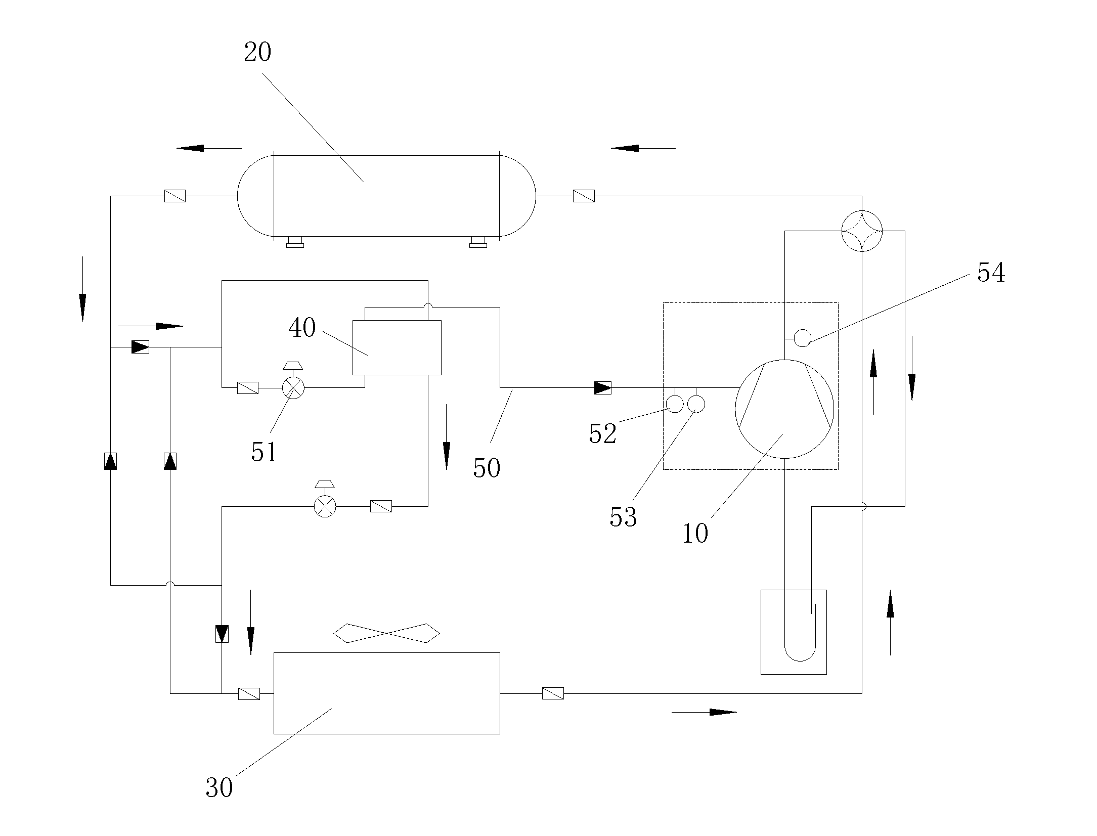
| PCT Filed: | September 26, 2017 | ||||||||||
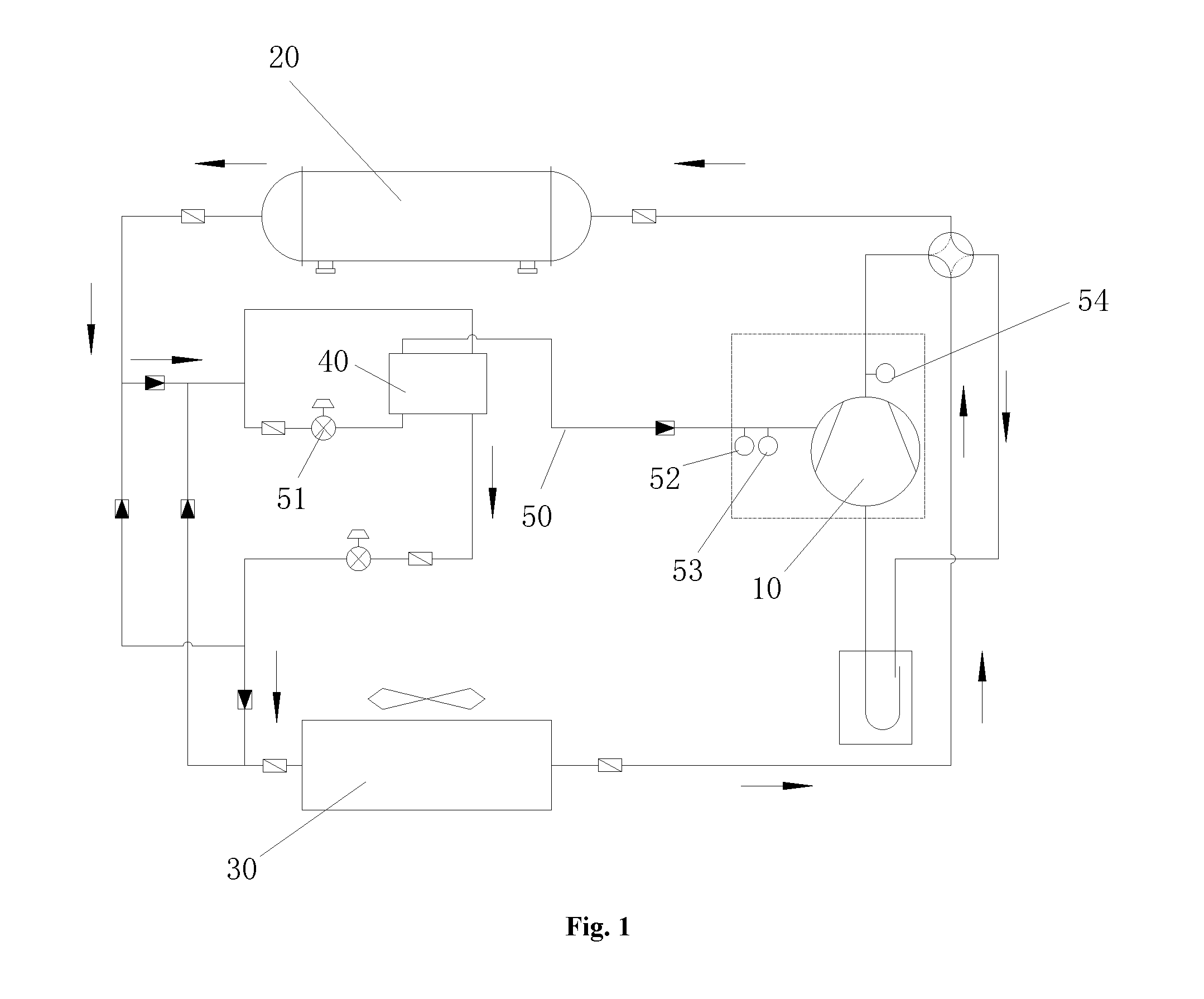
| PCT NO: | PCT/CN2017/103464 | ||||||||||
| 371 Date: | April 17, 2019 |
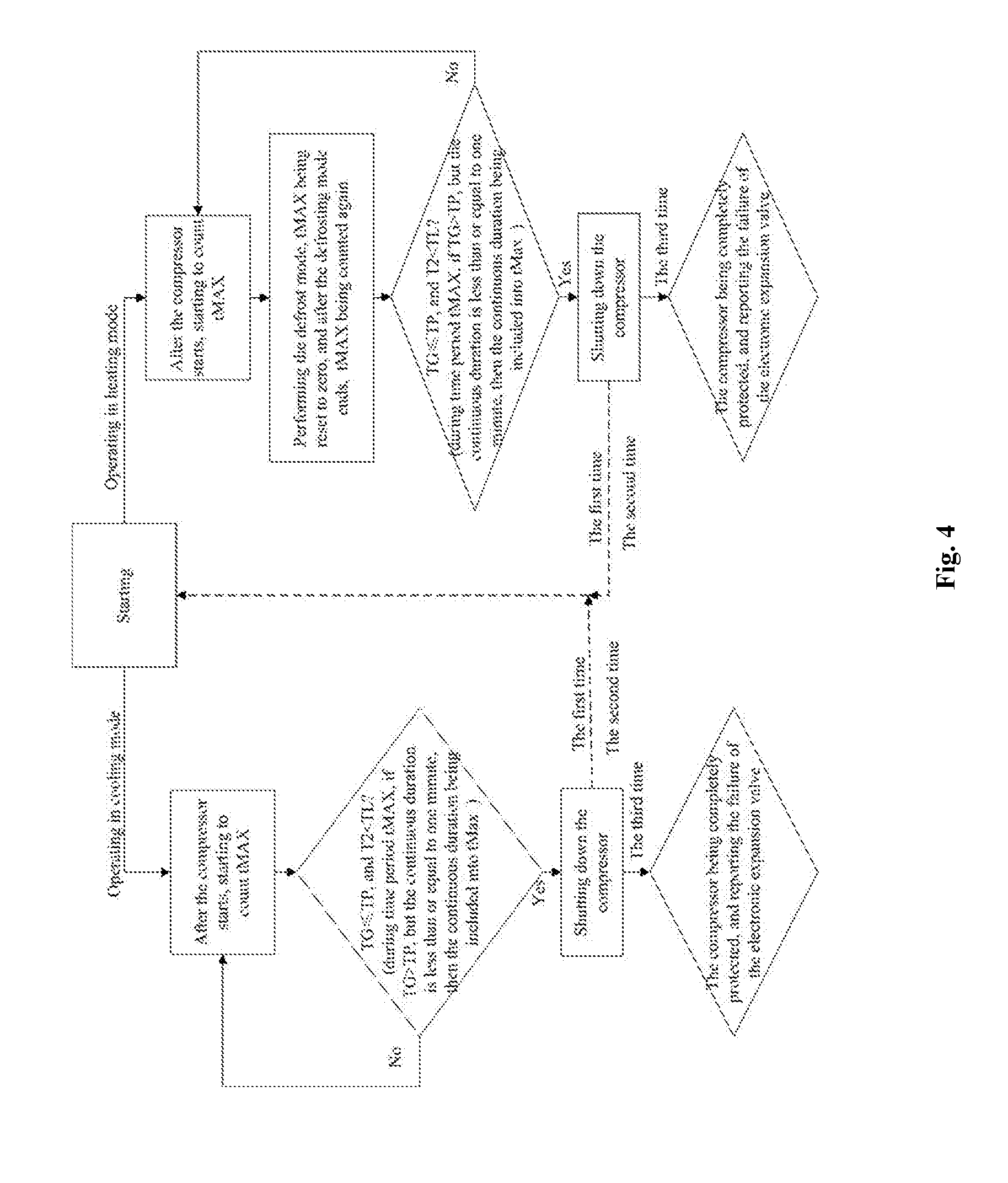
| Current U.S. Class: | 1/1 |
| Current CPC Class: | F24F 11/89 20180101; F25B 41/00 20130101; F24F 2110/00 20180101; F25B 2700/21152 20130101; F25B 2500/06 20130101; F24F 2110/10 20180101; F24F 11/41 20180101; F24F 11/72 20180101; F24F 11/62 20180101; F25B 49/022 20130101; F25B 2500/04 20130101; F25B 2700/21151 20130101; F24F 11/30 20180101; F24F 1/00 20130101; F24F 11/86 20180101; F24F 11/64 20180101; F24F 11/70 20180101 |
| International Class: | F24F 11/41 20060101 F24F011/41; F24F 11/86 20060101 F24F011/86 |
Foreign Application Data
| Date | Code | Application Number |
|---|---|---|
| Oct 17, 2016 | CN | 201610903627.7 |
Claims
1. A control method of an air conditioner, comprising: controlling a compressor of an air conditioner to be in an operating state or a shutdown state according to a superheat degree of injected vapor of the compressor and a continuous duration of the superheat degree of the injected vapor; and controlling the compressor to be in a shutdown state for maintenance according to a number of shutdown times of the compressor, wherein a gas supply pipeline of the compressor is maintained.
2. The control method according to claim 1, wherein, the control method comprises: controlling the compressor to be in the operating state continuously when the number of the shutdown times of the compressor is less than or equal to a first preset value; and controlling the compressor to be in the shutdown state for maintenance when the number of the shutdown times of the compressor is greater than the first preset value.
3. The control method according to claim 1, wherein, the continuous duration of the superheat degree further comprises a negative value continuous duration; when the negative value continuous duration of the superheat degree of the injected vapor reaches a second preset value, and during the negative value continuous duration, an exhaust temperature of the compressor remains less than a critical value of the exhaust temperature of the compressor, and the compressor is restored automatically to the operating state after being shut down.
4. The control method according to claim 3, wherein, the continuous duration of the superheat degree further comprises an offset value continuous duration; if the offset value continuous duration, in which the superheat degree of the injected vapor is greater than the offset value of the superheat degree continuously, is less than or equal to a third preset value, the offset value continuous duration is included into the negative value continuous duration.
5. The control method according to claim 4, wherein, the third preset value is t, wherein, 0<t.ltoreq.60 s.
6. The control method according to claim 2, wherein, the first preset value is N, wherein, 0<N.ltoreq.2.
7. The control method according to claim 1, wherein, in a heating mode and/or in a cooling mode of the air conditioner, the continuous duration of the superheat degree is tc, wherein, tc=t1-t0, wherein, t1>to, and t0 is a time instant when the superheat degree of the injected vapor begins to be less than an offset value of the superheat degree; or tc=t1-t0+t, wherein, t1 is a time instant when the superheat degree of the vapor injection begins to be greater than the offset value of the superheat degree after t0; t is a time period, in which the superheat degree of the vapor injection is greater than the offset value of the superheat degree; if t is greater than a fourth preset value, tc is reset to zero and counted again from a next time instant when the superheat degree of the vapor injection begins to be less than the offset value of the superheat degree.
8. The control method according to claim 7, wherein, in a cooling mode, when the air conditioner performs the defrost mode, the continuous duration is reset to zero; and the reset continuous duration is counted from a time instant when the superheat degree of the injected vapor begins to be less than or equal to the offset value of the superheat degree.
9. The control method according to claim 1, wherein, when the compressor is in a shutdown protection state, maintenance on an electronic expansion valve disposed in the gas supply pipeline of the compressor is performed.
10. An air conditioner, wherein, the air conditioner is controlled by the control method of claim 1, and the air conditioner comprises: a compressor, a first heat exchanger, a second heat exchanger, a gas supply device, which are in communication with each other; and a gas supply pipeline, wherein: a first end of the gas supply pipeline is in communication with an outlet end of the first heat exchanger; a second end of the gas supply pipeline is in communication with a gas supply port of the compressor; and at least part of the gas supply pipeline performs heat exchange with the gas supply device, to increase temperature of a refrigerant in the gas supply pipeline.
11. The air conditioner according to claim 10, wherein, the gas supply pipeline is provided with at least one of an electronic expansion valve, a pressure sensor and a first temperature sensor.
12. The air conditioner according to claim 10, wherein, a second temperature sensor is arranged in a discharge pipeline of the compressor.
13. The air conditioner according to claim 10, wherein, a third temperature sensor is arranged in the gas supply pipeline; and the third temperature sensor is disposed between an electronic expansion valve and the gas supply device.
14. The air conditioner according to claim 10, wherein, the control method comprises: controlling the compressor to be in the operating state continuously when the number of the shutdown times of the compressor is less than or equal to a first preset value; and controlling the compressor to be in the shutdown state for maintenance when the number of the shutdown times of the compressor is greater than the first preset value.
15. The air conditioner according to claim 10, wherein, the continuous duration of the superheat degree further comprises a negative value continuous duration; when the negative value continuous duration of the superheat degree of the injected vapor reaches a second preset value, and during the negative value continuous duration, an exhaust temperature of the compressor remains less than a critical value of the exhaust temperature of the compressor, and the compressor is restored automatically to the operating state after being shut down.
16. The air conditioner according to claim 15, wherein, the continuous duration of the superheat degree further comprises an offset value continuous duration; if the offset value continuous duration, in which the superheat degree of the injected vapor is greater than the offset value of the superheat degree continuously, is less than or equal to a third preset value, the offset value continuous duration is included into the negative value continuous duration.
17. The air conditioner according to claim 16, wherein, the third preset value is t, wherein, 0<t.ltoreq.60 s.
18. The air conditioner according to claim 14, wherein, the first preset value is N, wherein, 0<N.ltoreq.2.
19. The air conditioner according to claim 10, wherein, in a heating mode and/or in a cooling mode of the air conditioner, the continuous duration of the superheat degree is tc, wherein, tc=t1-t0, wherein, t1>to, and t0 is a time instant when the superheat degree of the injected vapor begins to be less than an offset value of the superheat degree; or tc=t1-t0+t), wherein, t1 is a time instant when the superheat degree of the vapor injection begins to be greater than the offset value of the superheat degree after t0; t is a time period, in which the superheat degree of the vapor injection is greater than the offset value of the superheat degree; if t is greater than a fourth preset value, tc is reset to zero and counted again from a next time instant when the superheat degree of the vapor injection begins to be less than the offset value of the superheat degree.
20. The air conditioner according to claim 19, wherein, wherein, in a heating mode, when the air conditioner performs the defrost mode, the continuous duration is reset to zero; and the reset continuous duration is counted from a time instant when the superheat degree of the injected vapor begins to be less than or equal to the offset value of the superheat degree.
Description
FIELD
[0001] The present invention relates to the field of air conditioner equipment, and particularly, to an air conditioner and a control method thereof.
BACKGROUND
[0002] The air-source heat pump absorbs the low-temperature heat energy from the air, which is transformed into high-temperature heat energy through the compressor. As a highly efficient, energy-saving and environmentally friendly heating technology, more and more air-source heat pumps are used in China. Conventional air-cooling air-source heat pumps most have a minimum environmental temperature of -15.degree. C. for heating operations. In order to broaden the heating operation range of the air-cooling air-source heat pump, Enhanced Vapor Injection technology is often used. The air-cooling heat pump using Enhanced Vapor Injection technology has a heating operation range as low as -25.degree. C. to -30.degree. C.
[0003] The throttling mechanism of an air-source heat pump typically is an electronic expansion valve. The electronic expansion valve is a throttling device, which controls the action of the valve needle by controlling the voltage or current applied to the expansion valve, to change the circulation area of the valve port, thereby achieving automatic regulation of flow volume. A common failure of the electronic expansion valve includes a jam, which will result in no flow or uncontrolled flow in the relevant flow path. The cause of the jam of the electronic expansion valve is usually that there are impurities in the system. The jam of the electronic expansion valve has a strong influence on the reliability of the unit. When there is no flow in the event of a jam, there will be a low-voltage protection or a high-temperature exhaust protection, and the unit can usually be protected quickly, thereby effectively protecting the compressor. When the flow is out of control (larger number of steps) in the event of a jam, the jam is usually difficult to be determined. If the unit cannot be quickly protected and operates for a long time, the compressor will be damaged, then it will be too late to find through inspection and analysis that the damage of the compressor is caused by the jam of the electronic expansion valve.
[0004] The electronic expansion valve for enhanced enthalpy injection of the air-cooling heat pump system using enhanced vapor injection technology is arranged in the sub pipeline of vapor injection increasing enthalpy, which is located downstream of the condenser, and performs functions of throttling and depressurizing the refrigerant in the enhanced vapor injection loop. When the electronic expansion valve for enhanced enthalpy injection is jammed at 0B or at a small number of steps, the superheat degree of the injected vapor will be a little larger, and the performance of the unit will be reduced, and the effects of lowering the exhaust temperature of the unit through increasing the injected vapor amount will be affected. The long-term operation of vapor injection will not affect the reliability of the compressor. If the exhaust high temperature protection occurs, it can prompt the operation and maintenance personnel of the unit to promptly analyze and check the cause of the failure, and the compressor will not be damaged. However, when the electronic expansion valve for enhanced enthalpy injection is jammed at a larger number of steps, the refrigerant in the enhanced vapor injection loop increases, which will cause liquid injection to run and make the superheat degree of the vapor injected to be negative. Long-term running of the liquid injection will cause hydraulic hit in the compressor, and result in abrasion due to insufficient lubrication as a result of diluted lubricant film of the compressor. Therefore, it is necessary to timely judge the failure behavior of the electronic expansion valve for enhanced enthalpy injection when the electronic expansion valve is jammed at a larger number of steps, to timely protect the unit and shut off the compressor, to check and analyze the reason of the jam of the electronic expansion valve for enhanced enthalpy injection, and to replace the electronic expansion valve for enhanced vapor injection in time, thus no serious after-sale damage of the compressor will occur.
SUMMARY
[0005] The main objective of the present invention is to provide an air conditioner and a control method thereof, so as to solve the problem that the compressor in the prior art is easily damaged.
[0006] In order to realize the objective above, according to one aspect of the present invention, a control method is provided. The control method comprises following steps: controlling a compressor of an air conditioner to be in an operating state or a shutdown state according to a superheat degree of injected vapor of the compressor and a continuous duration of superheat degree of the injected vapor; and controlling the compressor to be in a shutdown state for maintenance according to the number of shutdown times of the compressor, so as to maintain a gas supply pipeline of the compressor.
[0007] Further, the control method comprises: controlling the compressor to be in the operating state continuously when the number of shutdown times of the compressor is less than or equal to a first preset value; and controlling the compressor to be in the shutdown state for maintenance when the number of shutdown times of the compressor is greater than the first preset value.
[0008] Further, the continuous duration of superheat degree further comprises a negative value continuous duration; when the negative value continuous duration of the superheat degree of the injected vapor reaches a second preset value, and during the negative value continuous duration, an exhaust temperature of the compressor remains less than a critical value of the exhaust temperature of the compressor, and the compressor is restored automatically to the operating state after being shut down.
[0009] Further, the continuous duration of superheat degree further comprises an offset value continuous duration; if the offset value continuous duration, in which the superheat degree of the injected vapor is greater than the offset value of the superheat degree continuously, is less than or equal to a third preset value, the offset value continuous duration is included into the negative value continuous duration.
[0010] Further, the third preset value is t, wherein, 0<t.ltoreq.60 s.
[0011] Further, the first preset value is N, wherein, 0<N.ltoreq.2.
[0012] Further, in a heating mode or in a cooling mode of the air conditioner, the continuous duration of superheat degree is tc, wherein, tc=t1-t0, wherein, t1>to, and t0 is a time instant when the superheat degree of the injected vapor begins to be less than an offset value of the superheat degree; or tc=(t1-t0+t), wherein, t1 is a time instant when the superheat degree of the vapor injection begins to be greater than the offset value of the superheat degree after t0; t is a time period, in which the superheat degree of the vapor injection is greater than the offset value of the superheat degree; if t is greater than a fourth preset value, tc is reset to zero and counted again from a next time instant when the superheat degree of the vapor injection begins to be less than the offset value of the superheat degree.
[0013] Further, in a cooling mode, when the air conditioner performs the defrost mode, the continuous duration is reset to zero; and the reset continuous duration is counted from a time instant when the superheat degree of the injected vapor begins to be less than or equal to the offset value of the superheat degree.
[0014] Further, when the compressor is in a shutdown protection state, maintenance on an electronic expansion valve disposed in the gas supply pipeline of the compressor is performed.
[0015] According to another aspect of the present invention, an air conditioner is provided, which is the air conditioner described above. The air conditioner comprises: a compressor, a first heat exchanger, a second heat exchanger, a gas supply device, which are in communication with each other; and a gas supply pipeline, wherein: a first end of the gas supply pipeline is in communication with an outlet end of the first heat exchanger; a second end of the gas supply pipeline is in communication with a gas supply port of the compressor; and at least part of the gas supply pipeline performs heat exchange with the gas supply device, to increase temperature of a refrigerant in the gas supply pipeline.
[0016] Further, the gas supply pipeline is provided with at least one of an electronic expansion valve, a pressure sensor and a first temperature sensor.
[0017] Further, a second temperature sensor is arranged in a discharge pipeline of the compressor.
[0018] Further, a third temperature sensor is arranged in the gas supply pipeline; and the third temperature sensor is disposed between the outlet end of the first heat exchanger and the gas supply device.
[0019] As for the technical solution of the control method of the air conditioner, the control method includes controlling a compressor of an air conditioner to be in an operating state or a shutdown state according to a superheat degree of injected vapor of the compressor and a continuous duration of superheat degree of the injected vapor; and controlling the compressor to be in a shutdown state for maintenance according to the number of shutdown times of the compressor, so as to maintain a gas supply pipeline of the compressor. Such a method can effectively judge the working conditions of the compressor, so that the compressor can be timely maintained and be protected from being damaged for operating under severe working conditions, thereby improving the operation reliability of the compressor and the air conditioner.
BRIEF DESCRIPTION OF THE DRAWINGS
[0020] The accompanying drawings constituting a part of the present application are provided to further make the present invention understood. The illustrative embodiments of the present invention and the description are used to explain the present invention, but not intended to limit the present invention. In the drawings:
[0021] FIG. 1 is a schematic view illustrating an embodiment of an air conditioner system in a heating mode according to the present invention;
[0022] FIG. 2 is a schematic view illustrating an embodiment of the air conditioner system shown in FIG. 1 in a cooling mode;
[0023] FIG. 3 is a block diagram illustrating the working process of the compressor of the air conditioner shown in FIG. 1;
[0024] FIG. 4 is a block diagram illustrating the working process of the air conditioner shown in FIG. 1 in the cooling mode and in the heating mode respectively.
[0025] Wherein, the above figures include the following reference numerals:
[0026] 10. compressor; 20. first heat exchanger; 30. second heat exchanger; 40. gas supplying device; 50. gas supplying pipeline; 51. electronic expansion valve; 52. pressure sensor; 53. first temperature sensor; 54. second temperature sensor.
DETAILED DESCRIPTION OF THE INVENTION
[0027] It should be specified that, the embodiments and the features in the embodiments of the present invention may be combined with each other when there is no conflict. The embodiments of the present invention will be described in detail with reference to the accompanying drawings.
[0028] It should be noted that, the terminology herein is used for describing the specific embodiments, but not intended to limit the illustrative embodiments of the present invention. The singular terms herein are intended to include their plural unless specific descriptions are provided in context. It should be also understood that, the terms "include" and/or "comprise" in the description refer to including the features, steps, operations, devices, components, and/or combinations thereof.
[0029] It should be specified that the terms "first", "second", etc. in the description, the claims and the drawings in the present application are just used to distinguish similar objects, but not used to describe a specific order or an order of priority. It should be understood that such terms may be interchangeable under appropriate conditions, such that the embodiments of the present invention illustrated in the drawing or described herein can be implemented, for example, in a sequence other than the sequences illustrated or described herein. In addition, the terms "comprise", "have" and any variations thereof are intended to cover a non-exclusive inclusion. For example, a process, a method, a system, a product, or a device that includes a series of steps or units is not limited to those steps or units listed clearly, but may include other steps or units, which are not clearly listed, or which are inherent to such a process, a method, a product or a device.
[0030] For the convenience of description, terms of spatial relations such as "above", "over", "on a top surface", "upper", etc., may be used herein to describe the spatial position relationships of a device or a feature with other devices or features shown in the drawings. It should be understood that the terms of spatial relations are intended to include other different orientations in use or operation in addition to the orientation of the device described in the drawings. For example, if the device in the drawings is placed upside down, the device described as "above other devices or structures" or "over other devices or structures" will be positioned as "below other devices or structures" or "under other devices or structures". Thus, the exemplary term "above" may include both "above" and "below". The device can also be positioned in other different ways (rotating 90 degrees or at other orientations), and the corresponding explanations for the description of the spatial relations will be provided herein.
[0031] Now exemplary embodiments of the present invention will be described in detail with reference to the accompanying drawings. However, the exemplary embodiments may be implemented in different forms and should not be interpreted to limit the present invention. It should be understood that the embodiments are provided so that the disclosure of the present application will be thorough and complete, and the concepts of the exemplary embodiments will be sufficiently disclosed to those skilled in the art. In the drawings, the thicknesses of the layers and regions may be enlarged for the sake of clarity, and as the same reference numerals denote the identical devices, the description thereof is omitted.
[0032] As shown in FIGS. 1 through 4, according to an embodiment of the present invention, a control method of the air conditioner is provided.
[0033] Specifically, the control method of the air conditioner includes controlling the compressor of the air conditioner to be in an operating state or a shutdown state according to a superheat degree of injected vapor of the compressor and a continuous duration of superheat degree of the injected vapor; and controlling the compressor to be in a shutdown state for maintenance according to the number of shutdown times of the compressor, so as to maintain a gas supply pipeline of the compressor.
[0034] In this embodiment, such a method can effectively judge the working conditions of the compressor, so that the compressor can be timely maintained and be protected from being damaged for operating under severe working conditions, thereby improving the operation reliability of the compressor and the air conditioner.
[0035] Wherein, the method further includes: the compressor is controlled to be in an operating state when the number of shutdown times of the compressor is less than or equal to the first preset value; and the compressor is controlled to be in a shutdown state for maintenance when the number of shutdown times of the compressor is greater than the first preset value. Such a configuration can effectively avoid a false judgment, which is made under the conditions that the compressor shuts down itself under normal working conditions, and that the shutdown will not cause damage to the normal operation of the air conditioner and to the components of the compressor. Such a control method can improve the operation reliability of the air conditioner.
[0036] Further, the compressor is controlled to be in an operating state continuously when the number of shutdown times of the compressor is less than or equal to the first preset value; and the compressor is controlled to be in a shutdown state for maintenance when the number of shutdown times of the compressor is greater than the first preset value. Such a configuration can effectively detecting and controlling the working conditions of the compressor, and timely maintaining the compressor and the pipelines of the air conditioner.
[0037] Wherein, the first preset value is N, wherein 0<N.ltoreq.2. That is, when the compressor is shut down for the second time or for the first time, it can be controlled to be in the shutdown state for maintenance or in the operating state continuously.
[0038] The continuous duration includes a negative value continuous duration. When the negative value continuous duration of the superheat degree of the injected vapor reaches a second preset value, and during the negative value continuous duration, the exhaust temperature of the compressor remains less than the critical value of the exhaust temperature of the compressor, the compressor is restored automatically to the operating state after being shut down.
[0039] When the calculated negative value continuous duration of the superheat degree of the injected vapor reaches the maximum preset value, and during the negative value continuous duration of the superheat degree of the injected vapor, the exhaust temperature remains less than the critical value of the exhaust temperature, then the compressor is restored automatically to the operating state after being shut down. In calculating the negative value continuous duration tc of the superheat degree of the injected vapor, if a time period, in which the superheat degree of the injected vapor is greater than the offset value of the superheat degree, is less than or equal to the third preset value, the time period is included into the negative value continuous duration of the superheat degree. Such a configuration can effectively ensure the operation reliability of the air conditioner, and avoid false judgment caused by the working conditions and the like.
[0040] Wherein, the third preset value is t, wherein, 0<t.ltoreq.60 s. In this embodiment, t=60 s.
[0041] As shown in FIG. 3 and FIG. 4, in a heating mode and in a cooling mode of the air conditioner, the continuous duration is signed as tc, wherein tc is calculated as follows:
tc = { t 1 - t 0 , ( if TG .ltoreq. TP is kept till time instant t 1 ) t 1 - t 0 + t , ( if the continuous duration , in which TG > TP , is less than or equal to t ) 0 , ( if the continuous duration , in which TG > TP , is greater than t ) ##EQU00001##
[0042] Wherein, TG is the superheat degree of the injected vapor; TP is the offset value of the superheat degree; t0 is the time instant when the superheat degree of the injected vapor begins to be less than or equal to the offset value of the superheat degree; and t1 is the time instant when the superheat degree of the vapor injection begins to be greater than the offset value of the superheat degree after t0; it is known that t1>t0, that is, tc is counted from the time instant t0 when TG.ltoreq.TP. If TG.ltoreq.TP is kept till time instant t1, then the time (t1-t0) is included into tc; if TG>TP at the time instant t1, and if the continuous duration, in which TG>TP, is not greater than t, then continue to calculate tc, namely, tc=(t1-t0+t); if TG>TP at the time instant t1, and if the continuous duration, in which TG>TP, is greater than t, then reset the calculated tc, and tc is counted again from a next time instant when TG.ltoreq.TP; and afterwards, tc is calculated according to the above method.
[0043] In the heating mode, when the air conditioner performs the defrost mode, the continuous duration is reset to zero, and the reset continuous duration is counted from the time instant when the superheat degree of the injected vapor is less than or equal to the offset value of the superheat degree.
[0044] Preferably, when the compressor is in the shutdown protection state, maintenance on the electronic expansion valve disposed in the gas supply pipeline of the compressor is performed, which can improve the reliability of gas supply in the pipeline of the compressor, thereby effectively improving the compression performance of the compressor.
[0045] According to another aspect of the present invention, an air conditioner is provided, which is the air conditioner in the above embodiment. The air conditioner includes a compressor 10, a first heat exchanger 20, a second heat exchanger 30 and a gas supply device 40, which are in communication with each other. The first end of the gas supply pipeline 50 is in communication with the outlet end of the first heat exchanger 20; the second end of the gas supply pipeline 50 is in communication with the gas supply port of the compressor 10; and at least part of the gas supply pipeline 50 performs heat exchange with the gas supply device 40, to increase the temperature of the refrigerant in the gas supply pipeline 50. The operational reliability and the service life of the air conditioner can effectively be improved.
[0046] As shown in FIGS. 1 and 2, the gas supply pipeline 50 is provided with an electronic expansion valve 51, a pressure sensor 52 and a first temperature sensor 53. Wherein, the electronic expansion valve 51 is configured to control the gas supply opening in the gas supply pipeline 50; the pressure sensor 52 is configured to detect the pressure in the gas supply pipeline 50; and the first temperature sensor 53 is configured to detect the temperature in the gas supply pipeline 50. The superheat degree of the injected vapor of the compressor is calculated according to a conventional computational method.
[0047] Further, in order to improve the accuracy of the calculated result, a second temperature sensor 54 is further arranged in the discharge pipeline of the compressor 10 to detect the exhaust temperature at the discharge pipeline of the compressor. The nearer the second temperature sensor 54 is to the gas vent of the compressor, the more accurate the measurement is.
[0048] Of course, the gas supply pipeline 50 may not be provided with the pressure sensor 52, and alternatively, a third temperature sensor is arranged in the gas supply pipeline 50. The third temperature sensor is disposed between the electronic expansion valve 51 and the gas supply device 40.
[0049] A temperature sensor T3, namely the third temperature sensor, is disposed in the pipeline entering the plate heat exchanger namely the air supply device 40. The temperature sensor T1, namely the first temperature sensor 53, is arranged at the outlet of the plate heat exchanger and before the gas supply opening of the compressor. The third temperature sensor and the first temperature sensor 53 determine the conditions of liquid injection, and at this time TG=(T1-T3) (usually, TG is controlled to be 3.degree. C.-5.degree. C.). The judgment method, which determines the state of the refrigerant of the enhanced vapor injection according to the temperature difference between the gas supply pipeline 50 entering and the gas supply pipeline 50 leaving the heat exchanger in the enhanced vapor injection loop, is applicable for a compressor system which is more resistant to the liquid injection.
[0050] Specifically, in the enhanced vapor Injection system shown in FIG. 1, whose throttling device is an electronic expansion valve, a temperature sensor T1 and a pressure sensor P1 are disposed between the outlet of the gas supply device 40 and the inlet of the compressor, and a temperature sensor T2 is disposed in the discharge pipe at the compressor outlet. The superheat degree of the injected vapor is the difference between the temperature of the enhanced vapor injection and the saturation temperature corresponding to the pressure of the vapor injection, that is, TG=T1-TB.sub.(p1).
[0051] The zero-degree celsius offset value of the superheat degree is TP, and the value is from 0.5.degree. C. to 2.degree. C., which is based on the accuracy of the temperature sensor T1 and the actual situations. The critical value of the exhaust temperature is TL. When the exhaust temperature is too high, it can be reduced by increasing the vapor injection amount. However, the reduced exhaust temperature should not be lower than the critical value of the exhaust temperature. The critical value of the exhaust temperature is determined by the compressor type or recommended by the compressor manufacturer, and it is usually greater than 90.degree. C.
[0052] The negative value continuous duration of the superheat degree of the injected vapor is tc. The maximum preset negative value continuous duration of the superheat degree of the injected vapor is tMAX, which is matched and obtained through experimentation. In this embodiment, tMAX=20 min.
[0053] When the unit operates normally, the control program controls the electronic expansion valve according to the optimum superheat degree (3.degree. C.-8.degree. C. in this embodiment) of the vapor injection, and the steps of the electronic expansion valve for the enhanced vapor injection is continuously adjusted, so as to maintain the optimum superheat degree of the injected vapor. When the electronic expansion valve for the vapor injection is normal, the superheat degree of the injected vapor can be quickly controlled to be within the optimal range, and usually, the adjustment time is less than 15 minutes. At this time, the enhanced vapor injection effect is optimum. When the electronic expansion valve for the vapor injection is jammed at a larger number of steps, liquid injection will occur. At this time, the failure behavior is judged by the following processing method. Specifically, after the compressor of the unit starts running, if tc is equal to tMAX, and the exhaust temperature T2 is maintained to be less than TL during this process (continuous duration tc), then shut down the compressor of the corresponding system immediately. After each of the first two shutdowns of the compressor, the compressor is restored automatically to operate, and after the compressor is shut down for the third time, the compressor of the corresponding system is completely locked, and the failure of the electronic expansion valve for enhanced vapor injection is reported to warn the operation and maintenance personnel of timely checking and analyzing, timely replacing the electronic expansion valve for the enhanced vapor injection, so as to protect the compressor. There are basically no false alarms in this control method, the specific flow chart of which is shown in FIG. 3.
[0054] The calculation method of the negative value continuous duration tc of the superheat degree of the injected vapor is as follows: it is known that t1>t0; operate in the cooling mode; start the compressor; start to calculate tc after the electronic expansion valve for enhanced vapor injection is turned on; tc is counted from the time instant t0 when TG.ltoreq.TP; if TG.ltoreq.TP is kept till the time instant t1, then the time (t1-t0) is included into tc; if TG>TP at the time instant t1, and if the continuous duration, in which TG>TP, is not greater than one minute, then continue to calculate tc, namely, tc=(t1+-t0+60 s); if TG>TP at the time instant t1, and if the continuous duration, in which TG>TP, is greater than one minute, then reset the calculated tc, and tc is counted from a next time instant when TG.ltoreq.TP; and afterwards, tc is calculated according to the above method.
[0055] Operate in the heating mode; start the compressor; start to calculate tc after the electronic expansion valve for enhanced vapor injection is turned on; tc is counted from the time instant t0 when TG.ltoreq.TP; if TG.ltoreq.TP is kept till the time instant t1, then the time (t1 -t0) is included into tc; if TG>TP at the time instant t1, and if the continuous duration, in which TG>TP, is not greater than one minute, then continue to calculate tc, namely, tc=(t1-t0+60 s); if TG>TP at the time instant t1, and if the continuous duration, in which TG>TP, is greater than one minute, then reset the calculated tc, and tc is counted from a next time instant when TG.ltoreq.TP; and afterwards, tc is calculated according to the above method. If the unit operating in the heating mode enters the defrosting mode, the calculated tc is cleared; if the unit operating in the defrosting mode enters the heating mode, tc is counted again from the time instant when TG.ltoreq.TP, and then calculate it according to the above method.
[0056] Accurately, fast and timely judge the failure of the electronic expansion valve for enhanced vapor injection when it is jammed at a larger number of steps; timely shut down the compressor of the system, whose electronic expansion valve for enhanced vapor injection has a failure; warn the operation and maintenance personnel of timely analyzing and checking, and timely replacing the electronic expansion valve for enhanced vapor injection, so as to protect the compressor from severe damage. Reduce economic losses and avoid severe after-sale failure of the compressor damage.
[0057] What described above are preferable embodiments of the present invention, and they are not intended to limit the present invention. It will be understood by those skilled in the art that various modifications and improvements can be made. All these modifications, equivalent substitution and improvements made without departing from the sprits and principles of the present disclosure, are within the protection scope of the present invention.
* * * * *
uspto.report is an independent third-party trademark research tool that is not affiliated, endorsed, or sponsored by the United States Patent and Trademark Office (USPTO) or any other governmental organization. The information provided by uspto.report is based on publicly available data at the time of writing and is intended for informational purposes only.
While we strive to provide accurate and up-to-date information, we do not guarantee the accuracy, completeness, reliability, or suitability of the information displayed on this site. The use of this site is at your own risk. Any reliance you place on such information is therefore strictly at your own risk.
All official trademark data, including owner information, should be verified by visiting the official USPTO website at www.uspto.gov. This site is not intended to replace professional legal advice and should not be used as a substitute for consulting with a legal professional who is knowledgeable about trademark law.