Ceiling Fan
Whitmire; J. Porter
U.S. patent application number 16/267630 was filed with the patent office on 2019-08-08 for ceiling fan. The applicant listed for this patent is TTI (MACAO COMMERCIAL OFFSHORE) LIMITED. Invention is credited to J. Porter Whitmire.
| Application Number | 20190242392 16/267630 |
| Document ID | / |
| Family ID | 67475432 |
| Filed Date | 2019-08-08 |


| United States Patent Application | 20190242392 |
| Kind Code | A1 |
| Whitmire; J. Porter | August 8, 2019 |
CEILING FAN
Abstract
A ceiling fan includes a central hub, a motor disposed in the central hub, an impeller coupled to the motor, and a plurality of fan blades extending outwardly from the central hub. The central hub includes an interior chamber. The impeller is operable to rotate relative to the central hub. At least one of the plurality of fan blades includes a nozzle that defines an interior passageway and an outlet. The interior passageway of the nozzle is in fluid communication with the interior chamber of the central hub. The motor actuates the impeller for drawing air into the interior chamber of the central hub, forcing the air to the interior passageway of the nozzle, and expelling the air from the outlet.
| Inventors: | Whitmire; J. Porter; (Greenville, SC) | ||||||||||
| Applicant: |
|
||||||||||
|---|---|---|---|---|---|---|---|---|---|---|---|
| Family ID: | 67475432 | ||||||||||
| Appl. No.: | 16/267630 | ||||||||||
| Filed: | February 5, 2019 |
Related U.S. Patent Documents
| Application Number | Filing Date | Patent Number | ||
|---|---|---|---|---|
| 62627438 | Feb 7, 2018 | |||
| Current U.S. Class: | 1/1 |
| Current CPC Class: | F04D 25/088 20130101; F04D 29/601 20130101; F04F 5/00 20130101; F04D 25/10 20130101; F04F 5/16 20130101; F04F 5/46 20130101; F04D 29/34 20130101; F04D 27/004 20130101; F04D 29/388 20130101 |
| International Class: | F04D 25/08 20060101 F04D025/08; F04D 29/34 20060101 F04D029/34 |
Claims
1. A ceiling fan comprising: a central hub including an interior chamber; a motor disposed in the central hub; an impeller coupled to the motor for rotation relative to the central hub; and a plurality of fan blades extending outwardly from the central hub, at least one of the plurality of fan blades including a nozzle that defines an interior passageway and an outlet, and the interior passageway of the nozzle being in fluid communication with the interior chamber of the central hub; wherein the motor actuates the impeller for drawing air into the interior chamber of the central hub, forcing the air to the interior passageway of the nozzle, and expelling the air from the outlet.
2. The ceiling fan of claim 1, further comprising a drive assembly supported by the central hub, the drive assembly operable to move the plurality of fan blades relative to the central hub.
3. The ceiling fan of claim 2, wherein the drive assembly is operable to rotate the plurality of fan blades about a central axis of the central hub.
4. The ceiling fan of claim 2, wherein the drive assembly is operable to tilt a fan blade of the plurality of fan blades about a longitudinal axis that is perpendicular to a central axis of the central hub.
5. The ceiling fan of claim 2, wherein the drive assembly includes: a first motor; a first ring gear coupled to the first motor; the first ring gear being configured to induce rotation of the plurality of fan blades; a second motor; and a second ring gear coupled to the second motor, the second ring gear being configured to induce oscillation of the plurality of fan blades.
6. The ceiling fan of claim 1, wherein the central hub includes an inlet in fluid communication with the interior chamber, and wherein the air enters the interior chamber through the inlet.
7. The ceiling fan of claim 6, wherein the inlet is positioned above the plurality of fan blades.
8. The ceiling fan of claim 1 further comprising a light positioned below the plurality of fan blades.
9. The ceiling fan of claim 1, wherein each of the plurality of fan blades includes a nozzle that defines an interior passageway and an outlet.
10. The ceiling fan of claim 1, wherein each of the plurality of fan blades comprises multiple outlets.
11. The ceiling fan of claim 10, wherein the multiple outlets are formed in a decorative design.
12. A ceiling fan comprising: a central hub having a central axis; a plurality of fan blades extending outwardly from the central hub, a fan blade of the plurality of fan blades having a longitudinal axis that is perpendicular to the central axis; and a drive assembly supported by the central hub, the drive assembly being operable to rotate the plurality of fan blades relative to the central axis of the central hub, and the drive assembly being operable to rotate the fan blade relative to the longitudinal axis.
13. The ceiling fan of claim 12, wherein: each of the plurality of fan blades includes a respective longitudinal axis, the drive assembly is configured to simultaneously rotate each of the plurality of fan blades relative to the respective longitudinal axis.
14. The ceiling fan of claim 13, wherein each of the plurality of fan blades is independently rotatable to a respective tilt angle by the drive assembly, and wherein at least a first tilt angle is different from a second tilt angle.
15. The ceiling fan of claim 12, wherein the drive assembly includes a motor operable to rotate the plurality of fan blades relative to the central axis.
16. The ceiling fan of claim 12, wherein the drive assembly includes a ring gear secured to a section of the central hub that supports the plurality of fan blades, and wherein a motor is coupled to the ring gear to rotate the ring gear for inducing rotation of the plurality of fan blades relative to the central axis.
17. The ceiling fan of claim 12, wherein the each of the plurality of fan blades includes a respective oscillation gear, and wherein the drive assembly is configured to move each respective oscillation gear to tilt each of the plurality of fan blades.
18. The ceiling fan of claim 12, further comprising: a motor disposed in the central hub; and an impeller coupled to the motor; the motor being configured to actuate the impeller to draw air into the central hub and force the air through the plurality of fan blades.
19. A ceiling fan comprising: a central hub including: an interior chamber; a first motor disposed in the central hub; and an impeller coupled to the first motor; a plurality of fan blades extending outwardly from the central hub, each of the plurality of fan blades including a nozzle and an oscillation gear, each nozzle defining an interior passageway and an outlet, and the interior passageway of each nozzle being in fluid communication with the interior chamber of the central hub; a drive assembly supported by the central hub, the drive assembly including: a ring gear coupled to a respective oscillation gear of each of the plurality of fan blades; and a second motor coupled to the ring gear, wherein the second motor is configured to move the ring gear relative to a central axis of the hub to tilt each of the plurality of fan blades relative to a longitudinal axis that is perpendicular to the central axis; and wherein the first motor is configured to actuate the impeller to draw air into the interior chamber of the central hub, force the air to the interior passageways of the nozzles, and expel the air out from the outlets of the plurality of fan blades.
20. The ceiling fan of claim 19, wherein the drive assembly further comprises: a second ring gear supporting the plurality of fan blades; and a third motor coupled to the second ring gear, the third motor being configured to rotate the second ring gear for rotating the plurality of fan blades about the central axis.
Description
CROSS-REFERENCE TO RELATED APPLICATIONS
[0001] This application claims priority to U.S. Provisional Patent Application No. 62/627,438, filed Feb. 7, 2018, the entire contents of which are hereby incorporated by reference.
BACKGROUND
[0002] The present subject matter relates to ceiling fans, and in particular, to bladeless ceiling fans.
[0003] Ceiling fans may be mounted to ceilings to circulate air within rooms. Some fans include blades or impellers positioned within a housing such that the blades or impellers are not visible to a user. Such fans are referred to as bladeless fans. A bladeless fan typically draws air through an opening in the housing and guides the air through inner pathways until the air is pushed out of the inner pathways in a given direction. Taking advantage of the Bernoulli principle and Coanda effect, high velocity air expelled from the bladeless fans draws additional air into the airflow zone, thereby increasing a total air flow.
SUMMARY
[0004] In one embodiment, a ceiling fan includes a central hub, a motor disposed in the central hub, an impeller coupled to the motor, and a plurality of fan blades extending outwardly from the central hub. The central hub may include an interior chamber. The impeller may be operable to rotate relative to the central hub. At least one of the plurality of fan blades may include a nozzle that defines an interior passageway and an outlet. The interior passageway of the nozzle may be in fluid communication with the interior chamber of the central hub. The motor may actuate the impeller for drawing air into the interior chamber of the central hub, forcing the air to the interior passageway of the nozzle, and expelling the air from the outlet.
[0005] In another embodiment, a ceiling fan includes a central hub, a plurality of fan blades extending outwardly from the central hub, and a drive assembly supported by the central hub. The central hub may have a central axis. A fan blade of the plurality of fan blades may have a longitudinal axis that is perpendicular to the central axis. The drive assembly may be operable to rotate the plurality of fan blades relative to the central axis of the central hub. The drive assembly may be operable to rotate the fan blade relative to the longitudinal axis.
[0006] In a further embodiment, the ceiling fan includes a central hub, a plurality of fan blades extending outwardly from the central hub, and a drive assembly supported by the central hub. The central hub may include an interior chamber, a first motor that may be disposed in the central hub, and an impeller that may be coupled to the first motor. Each of the plurality of fan blades may include a nozzle and an oscillation gear. Each nozzle may define an interior passageway and an outlet. The interior passageway of each nozzle may be in fluid communication with the interior chamber of the central hub. The drive assembly may include a ring gear that may be coupled to a respective oscillation gear of each of the plurality of fan blades and a second motor that may be coupled to the ring gear. The second motor may be configured to move the ring gear relative to a central axis of the hub to tilt each of the plurality of fan blades relative to a longitudinal axis that is perpendicular to the central axis. The first motor may be configured to actuate the impeller to draw air into the interior chamber of the central hub, force the air to the interior passageways of the nozzles, and expel the air out from the outlets of the plurality of fan blades.
[0007] Other aspects of the present subject matter will become apparent by consideration of the detailed description and accompanying drawings.
BRIEF DESCRIPTION OF THE DRAWINGS
[0008] FIG. 1 is a perspective view of a ceiling fan.
[0009] FIG. 2 is a cross-sectional view of the ceiling fan of FIG. 1 taken along section line A-A.
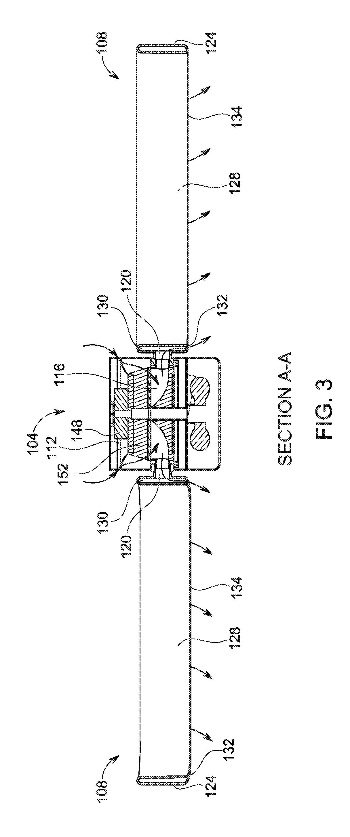
[0010] FIG. 3 is a cross-sectional view of the ceiling fan of FIG. 1 taken along section line A-A and depicting airflow through the ceiling fan.
[0011] FIG. 4 is a cross-sectional view of a portion of the ceiling fan of FIG. 1 taken along section line B-B.
[0012] FIG. 5 is a bottom view of a portion of the ceiling fan of FIG. 1 with a portion of a central hub removed.
[0013] FIG. 6 is a perspective view of a ceiling fan according to another embodiment of the present subject matter.
[0014] FIG. 7 is a perspective view of a ceiling fan according to another embodiment of the present subject matter.
[0015] FIG. 8 is a perspective view of a ceiling fan according to another embodiment of the present subject.
[0016] Before any embodiments are explained in detail, it is to be understood that the present subject matter is not limited in its application to the details of construction and the arrangement of components set forth in the following description or illustrated in the following drawings. The present subject matter is capable of other embodiments and of being practiced or of being carried out in various ways.
DETAILED DESCRIPTION
[0017] FIGS. 1-8 illustrate ceiling fans, generally designated 100, 200, 300. The ceiling fans 100, 200, 300 may be used within rooms to create airflows within the rooms. Such airflows may be useful for improved heating of the room, improved cooling of the room, and/or the like.
[0018] With reference to FIGS. 1-3, the ceiling fan 100 may include a central hub 104 and a plurality of fan blades 108 positioned circumferentially around the central hub 104. The plurality of fan blades 108 may be coupled to and extend outwardly from the central hub 104. The central hub 104 may include at least one inlet 112 and an interior chamber 116 (FIGS. 2-3). The inlet 112 may be in fluid communication with the interior chamber 116. The inlet 112 may be defined by one or more openings in the central hub 104. In the illustrated embodiment, the inlet 112 may be positioned above the plurality of fan blades 108 (e.g., more proximate the ceiling). In other embodiments, the inlet 112 may be positioned elsewhere on the central hub 104 (e.g., on an exterior side of the central hub 104, on a wall of the central hub 104, and/or the like).
[0019] The fan blades 108 may be coupled to the central hub 104 by way of a stem 120. In some embodiments, the stem 120 may define a channel that may communicate with the interior chamber 116 of the central hub 120. One or more of the fan blades 108 may be formed as and/or include a nozzle 124. The nozzle 124 may include or define a longitudinal axis B that extends along a length of the corresponding fan blade 108. As shown in the illustrated embodiment, each nozzle 124 may be formed as a generally annularly shaped nozzle 124 that defines a central aperture 128 extending through the nozzle 124, an interior passageway 130 (FIGS. 2-3) in fluid communication with the channel of the stem 120, and/or an outlet 132 that may expel air from the fan blade 108.
[0020] The interior passageway 130 (FIGS. 2-3) of each nozzle 124 may be in fluid communication with the interior chamber 116 of the central hub 104 by way of the internally disposed channel of the stem 120, and such passageway may extend uninterrupted around a perimeter the nozzle 124 of and/or or along a length of the nozzle 124. As shown in the illustrated embodiment, the outlet 132 may be formed along a lower edge 134 of the nozzle 124, the lower edge 134 being disposed a distance away from a ceiling to which the ceiling fan 100 may attach. The outlet 132 may be configured to expel air out of the ceiling fan 100 in a downward direction relative to the central hub 104, as depicted in FIG. 3. Additional ceiling fan embodiments may include additional outlets 132 and/or an outlet 132 positioned at alternative locations along the fan blades 108. The outlets 132 may also be angled (e.g., by way of providing angled and/or overlapping outlet surfaces or walls) to expel the air in a direction angled relative to the central hub 104. In the illustrated embodiment, the ceiling fan 100 may include four fan blades 108. The fan blades 108 may be equally or non-equally spaced about the central hub 104. In other embodiments, the ceiling fan 100 may include fewer or more fan blades 108 and may include fan blades of differing shapes (e.g., circular, rectangular, elliptical, and/or the like), lengths, and/or the like.
[0021] With reference to FIG. 2, the central hub 104 may include a first, upper section 136, a second, middle section 140, and a third, lower section 144. In some embodiments, the central hub 104 may include fewer or additional sections. The upper section 136 may be configured to attach (e.g., via mounting, adhering, coupling, and/or the like) to a ceiling or other suitable surface or structure (e.g., a rafter, and/or the like) of a building. The upper section 136 may include suitable structures for mounting to the ceiling, such as a bracket for coupling directly to the ceiling or for receiving a downrod. The upper section 136 may also define the inlet 112. The middle section 140 is located between the upper section 136 and the lower section 144 and supports the fan blades 108. As shown in the illustrated embodiment, the lower section 144 may support a light emitting portion 146 of the ceiling fan 100. The light emitting portion 146 may include one or more incandescent bulbs. In other embodiments, the light emitting portion 146 may include one or more light emitting diodes (LEDs) or other suitable light emitters or elements. The lower section 144 may also include a lens 147 or other suitable cover for covering the light emitters of the light emitting portion 146. The various sections (e.g., 136, 140, 144) of the central hub 104 may be secured to each other such that the middle section 140 may be able to rotate respective to (e.g., about, around, and/or the like) a central axis C of the central hub 104, while the upper section 136 and/or the lower section 144 may remain stationary.
[0022] The ceiling fan 100 may also include a motor 148 (e.g., a first motor) and an impeller 152. The motor 148 and the impeller 152 may be disposed proximate to the central hub 104, and in some embodiments be positioned within the interior chamber 116 of the central hub 104. As shown in the illustrated embodiment, the motor 148 may be positioned within the upper section 136 of the central hub 104. The motor 148 may be electrically coupled to a power source within a room in which the ceiling fan 100 may be positioned. Alternatively, the motor 148 may be electrically coupled to a battery supported by the central hub 104, such as a battery pack. The impeller 152 may be coupled to an output shaft (not shown) of the motor 148. The motor 148 may rotate the impeller 152 respective to the output shaft to induce an airflow that draws air into the interior passageways of the central hub 104 through the air inlet 112. In the illustrated embodiment, the motor 148 may rotate the impeller 152 about the central axis C of the central hub 104. The impeller 152 may be associated with a bladeless fan operable by way of bladeless technology for generating an airflow through ceiling fan 100. In this way, bladeless technology may be used in conjunction with bladed technology imparted by way of employing fan blades 108 for producing a desired airflow in a room.
[0023] With reference to FIGS. 2-3, during operation of the ceiling fan 100, the motor 148 may rotate the impeller 152 to draw air from outside the ceiling fan 100 into the ceiling fan 100 through the air inlet 112 and into the interior chamber 116 of the central hub 104. Once air is inside the central hub 104, the impeller 152 may propel the air through the channels of the stems 120 and into the interior passageways 130 of the plurality of fan blades 108. The air may travel around the entirety of the fan blades 108, in some embodiments. As the air circulates through the interior passageways 130 of the fan blades 108, the air may be expelled out of the ceiling fan 100 through the outlets 132 at a relatively high velocity. Due to natural convection and the high velocity at which the air is expelled from the outlets 132, surrounding air may be drawn through the central apertures 128 of the fan blades 108 through inducement of air behind the fan blades 108, while additional airflow combines with the induced air through entrainment of air on edges of the fan blades 108, causing an amplifying effect. In this way, the ceiling fan 100 may provide improved air circulation and/or airflow in a room for improved heating, cooling, ventilation, and/or the like.
[0024] In some embodiments, each of the fan blades 108 may include a separate motor and a separate impeller coupled to the separate motor for inducing an airflow in the fan blade 108, rather than employing the shared motor 148 and impeller 152 described above. In such embodiments, each of the fan blades 108 may also include an air inlet positioned adjacent the stem 120.
[0025] With reference to FIGS. 4-5, the ceiling fan 100 may include a drive assembly 154 for rotating and/or tilting the fan blades 108 for inducing a desired airflow. The drive assembly 154 may include a first gear 156 (FIG. 5) and a second motor 160 (FIG. 5). The first gear 156 may be a ring gear and, more particularly, an inner ring gear. The first gear 156 may be positioned within and coupled to the middle section 140 of the central hub 104 such that the first gear 156 and the central hub 104 share the central axis C (e.g., the central hub 104 and first gear 156 may be centered respective to the central axis C, the central hub 104 and first gear 156 may co-rotate respective to the central axis C in a same or different directions, and/or the like). The first gear 156 may also be secured to the middle section 140 for causing rotation of the middle section 140 (and, thereby, the fan blades 108) about the central axis C relative to the upper section 136 and the lower section 144. The second motor 160 may be positioned within the middle section 140 and be mounted on an upper plate 164 of the lower section 144. The second motor 160 may include a respective motor gear or pinion 168 (FIG. 5) coupled to (e.g., intermeshed with) the first gear 156. The second motor 160 may be operable to rotate the first gear 156, the middle section 140 of the central hub 104, and/or the fan blades 108 about the central axis C as the motor pinion 168 drives the first gear 156.
[0026] When power is supplied to the second motor 160, the second motor 160 may rotate the motor pinion 168. Since the motor pinion 168 and the first gear 156 may be meshed, rotation of the first gear 168 may cause the first gear 156 to rotate. Due to the first gear 156 being secured to the middle section 140 of the central hub 104, rotation of the first gear 156 may cause the middle section 140, and thus the fan blades 108, to rotate about the central axis C of the central hub 104. During rotation of the middle section 140, the upper section 136 and the lower section 144 may remain stationary. The speed of rotation of the middle section 140 and the fan blades 108 may be determined by the revolutions per minute (rpm) of the second motor 160. Additionally, or alternatively, the direction of the rotation of the fan blades 108 may be determined by the direction of rotation of the second motor 160.
[0027] In certain embodiments, the rpm and the direction of rotation of the second motor 160 may be set and/or controlled by a user input (e.g., an app on a smartphone or computer, a remote control, a pull cord, an actuator on the central hub 104, etc.). In additional embodiments, the rpm and the direction of rotation of the second motor 160 may be determined and set by a control scheme that measures environmental parameters (e.g., room temperature, room humidity, and/or the like).
[0028] Still referring to FIGS. 4 and 5, and in some embodiments, the drive assembly 154 may additionally include a second gear 172 and a respective motor, in this case a third motor 176. The second gear 172 may be a ring gear and, more particularly, an outer ring gear. The second gear 172 may be positioned within the middle section 140 of the central hub 104 such that the second gear 172 and the central hub 104 may be co-axial respective to central axis C. The second gear 172 may also be positioned outside of (e.g., around) the first gear 156. The third motor 176 may be positioned within the middle section 140 and mounted on the upper plate 164 of the lower section 144. In the illustrated embodiment, the second motor 160 and the third motor 176 may be positioned on diametrically opposite sides of the upper plate 164 to help balance the central hub 104. In other embodiments, the second motor 160 and the third motor 176 may be positioned adjacent each other or elsewhere on the central hub 104. The third motor 176 may include a respective motor gear or pinion 180 coupled to (e.g., intermeshed with) the second gear 172. Each fan blade 108 may also include an oscillation gear 184 coupled to (e.g., intermeshed with) the second gear 172. The oscillation gears 184 may be disposed on, over, around and/or proximate to the stems 120 of the plurality of fan blades 108, and be oriented so that a center of an annular opening of the oscillation gears 184 are substantially orthogonal to the central axis C. The motor pinion 180 may engage teeth formed on one side of the second gear 172, while the oscillation gears 184 may engage teeth formed on an opposite side of the second gear 172. The third motor 176 may be operable to move the second gear 172 respective to the central axis C to tilt (e.g., by way of rotating) the fan blades 108 about their respective longitudinal axes B as the motor pinion 180 drives the second gear 172, which drives the oscillation gears 184. In this way, air may be expelled from the fan blades 108 in a preferential direction by way of tilting the fan blades 108 towards the preferential direction. Additionally, or alternatively, in this way, the fan blades 108 may be caused to repeatedly tilt in opposing directions and, thus, oscillate respective to the fan hub 104 for improving circulation of air in spaces adjacent to and/or surrounding the ceiling fan 100.
[0029] When power is supplied to the third motor 176, the third motor 176 may rotate the motor pinion 180. Since the motor pinion 180 and the second gear 172 may be meshed, rotation of the motor pinion 180 causes the second gear 172 to move (e.g., rotate at least a small degree about the central axis C). Due to the second gear 172 being meshed with the oscillation gears 184 of the fan blades 108, as the outer ring 172 rotates, the oscillation gears 184 may also rotate, tilting the fan blades 108 relative to the central hub 104 about respective longitudinal axes B. The third motor 176 may rotate the fan blades 108 without moving the middle section 140 of the central hub 104. Tilting of the fan blades 108 may include a continuous tilt (e.g., rotation) of the fan blades 108 about their longitudinal axes B as the ceiling fan 100 operates, a discrete movement to a desired tilt angle, and/or oscillation of the fan blades 108 back-and-forth through an angle of motion (e.g., +/-15 degrees respective to an axis B, +/-30 degrees respective to an axis B, +/-45 degrees respective to an axis B, +/-90 degrees respective to an axis B, and/or the like). In the illustrated embodiment, the second gear 172 and the third motor 176 may cause all of the fan blades 108 to tilt together, simultaneously (e.g., in a simultaneous direction, at the same time, and/or the like) in a coordinated manner. Additionally, or alternatively, the drive assembly 154 may be configured to independently tilt each of the fan blades 108. Similar to the second motor 160, the speed of tilt of the fan blades 108 may be based on the rpm of the third motor 176. The amount (i.e., degree) of tilt of the fan blades 108 may be determined by the amount of rotations of the third motor 176. The direction of tilt of the fan blades 108 may be determined by the direction of rotation of the second motor 176.
[0030] In certain embodiments, the rpm, the amount of completed rotations, and/or the direction of rotation of the third motor 176 may be set by a user input (e.g., an app on a smartphone or computer, a remote control, a pull cord, an actuator on the central hub 104, and/or the like). In additional embodiments, the rpm, the amount of completed rotations, and the direction of rotation of the third motor 176 may be determined and set by a control scheme that measures environmental parameters (e.g., room temperature, room humidity, and/or the like).
[0031] In the depicted embodiment, rotating, tilting, and oscillating of the fan blades 108 relative to the central hub 104 may be used to direct an airflow towards specific locations within a room and generate additional airflow while maintaining the amplification of airflow that is produced by the fan blades 108. For example, rotation of the fan blades 108 relative to the central hub 104 may circulate the airflow throughout the room. Whereas the airflow produced by the fan blades 108 may be primarily directed in a direction downward from each fan blade 108, as the fan blades 108 rotate, the airflow produced by each fan blade 108 may be circulated and amplified. Tilting the fan blades 108 relative to the central hub 104 may direct the airflow produced by each fan blade 108. While in a neutral (e.g., horizontal) position, the fan blades 108 of the depicted embodiment may direct the airflow downward, whereas tilting the fan blades 108 may change the angle in which the airflow is directed. By oscillating the fan blades 108, air may be expelled from the outlets 132 in a range of directions, creating a greater airflow. Combining rotating and tilting of the fan blades 108 may allow the airflow being output by the fan blades 108 to be customized and/or controlled based on a desired location for the airflow and/or the amount of circulation of the airflow within the room. For example, tilting and rotating the fan blades 108 may provide airflow to a larger circumferential area than would solely rotating the fan blades 108.
[0032] In alternative embodiments, the fan blades 108 may be operable to either tilt relative to the central hub 104 or to rotate about the central axis C, but not both. In some embodiments, the fan blades 108 may be stationary relative to the central hub 104, meaning the fan blades 108 may neither rotate about the central axis C nor tilt relative to the central hub 104.
[0033] In some embodiments, the ceiling fan 100 may include a single motor that both causes rotation of the fan blades 108 about the central axis C and tilting/oscillating of the fan blades 108 about respective axes B of the fan blades 108. In further embodiments, the ceiling fan 100 may include a single motor that rotates the impeller 152, rotates the fan blades 108 about the central axis C, and tilts/oscillates the fan blades 108 about their respective axes B.
[0034] FIGS. 6 and 7 illustrate another embodiment of a ceiling fan, generally designated 200. The ceiling fan 200 may be similar in form and/or function to the ceiling fan 100 described above, and only the differences between the ceiling fan 200 and the ceiling fan 100 above are described in detail below.
[0035] The ceiling fan 200 may include a central hub 204, a light 208 positioned below the central hub 208, and a plurality of fan blades 212 disposed around the central hub 204. Although not illustrated, the ceiling fan 200 may include a mount on the top side of the central hub 204 to mount the ceiling fan 200 to a ceiling (or surface) of a room. Inside the central hub 204 may be a motor (not shown) coupled to a power source to energize the motor and an impeller (not shown) coupled to an output shaft of the motor for rotation within the central hub 204. The central hub 204 may further include an air inlet 216 connected to an interior chamber surrounding the motor and impeller. In some embodiments, in addition to powering the impeller of a fan that draws air into the air inlet 216, the motor may be capable of rotating and/or tilting the plurality of fan blades 212 respective to the central hub 204. In other embodiments, the ceiling fan 200 may include additional motors that rotate and/or tilt the fan blades 208 as described herein.
[0036] With continued reference to FIGS. 6 and 7, each of the plurality of fan blades 212 extends radially from the central hub 204 and may include an interior passageway (not shown) that may be connected to the interior chamber of the central hub 204. Each of the plurality of fan blades 212 may include multiple outlets 220. One outlet 220 may be positioned on one side of the fan blade 212 and generally extend the length of the fan blade 212, and another outlet 220 may be positioned on another (e.g., an opposite) side of the fan blade 212 and generally extend the length of the fan blade 212. More than two outlets 220 may be provided per fan blade 212 in some embodiments. In some embodiments the outlets 220 may be disposed adjacent and/or proximate to an upper surface of the corresponding fan blade 212. As air is expelled from the outlets 220, the air may be routed across or over and follow the outer surface of the fan blades 212. In the illustrated embodiment, the ceiling fan 200 may include five fan blades 212. In other embodiments, the ceiling fan 200 may include fewer or more fan blades 212, including an even quantity of fan blades 212 or an odd quantity of fan blades 212.
[0037] As shown in FIG. 7, the fan blades 212 may include decorative covers 224. The covers 224 may be integrally formed with the fan blades 212 or removably attached to the fan blades 212. The covers 224 may include colors, designs, shapes, patterns, and the like. In some embodiments, air may be expelled from the decorative shapes or patterns by way of circulating air through the fan as described herein. That is, in some embodiments, the outlets may be provided as a decorative shape, pattern, or design.
[0038] During operation of the ceiling fan 200, the motor may rotate the impeller to draw air from outside the ceiling fan 200 through the air inlet 216 and into the interior chamber of the central hub 204. Once air is inside the interior chamber, the impeller may force the air into the interior passageways of each of the fan blades 212 and expel the air out through the air outlets 220 at a high velocity. Due to natural convection and the high velocity at which the air is expelled from the outlets 220, an amplifying airflow effect may be created in a space 228 defined between consecutive fan blades 212. In addition, the motor may rotate the fan blades 212 about the central hub 204 to vary the position of the outlets 220.
[0039] FIG. 8 illustrates another embodiment of a ceiling fan, generally designated 300. The ceiling fan 300 may be similar in form and/or function to the ceiling fan 200 described above, and only the differences between the ceiling fan 300 and the ceiling fan 200 above are described in detail below.
[0040] The ceiling fan 300 may include a central hub 304 and a plurality of fan blades 312 positioned circumferentially around the central hub 304. Each fan blade 312 may define a longitudinal axis 316. The illustrated longitudinal axes 316 may be centrally positioned through each of the plurality of fan blades 312. The fan blades 312 may be asymmetrical respective to the axes 316. The fan blades 312 may be formed in an aerodynamic shape having curved and/or sloped surfaces and/or edges. The fan blades 312 may be oscillated respective to the longitudinal axes 316, as indicated by arrows A. In some embodiments, stems of the fan blades 312 may include gear teeth on an outside surface that extend circumferentially about the stems (e.g., as described above in regard to ceiling fan 100). Each fan blade 312 may include a motor with a drive gear that connects to the gear teeth on the stem. During operation of the ceiling fan 300, each motor may interact with the gear teeth of the corresponding fan blade 312 to rotate the fan blade. The motor for each fan blade 304 may drive the stems 120 to rotate relative to the central hub 304 to facilitate oscillation. By oscillating the fan blades 312, air may be expelled from outlets of the fan blades 312 in a range of directions, creating a greater airflow. In other embodiments, the ceiling fan 300 may employ one motor to rotate and oscillate the fan blades 312, for example, by way of a gear ring.
[0041] Various features of the present subject matter are set forth in the following claims.
* * * * *
D00000
D00001
D00002
D00003
D00004
D00005
D00006
D00007
XML
uspto.report is an independent third-party trademark research tool that is not affiliated, endorsed, or sponsored by the United States Patent and Trademark Office (USPTO) or any other governmental organization. The information provided by uspto.report is based on publicly available data at the time of writing and is intended for informational purposes only.
While we strive to provide accurate and up-to-date information, we do not guarantee the accuracy, completeness, reliability, or suitability of the information displayed on this site. The use of this site is at your own risk. Any reliance you place on such information is therefore strictly at your own risk.
All official trademark data, including owner information, should be verified by visiting the official USPTO website at www.uspto.gov. This site is not intended to replace professional legal advice and should not be used as a substitute for consulting with a legal professional who is knowledgeable about trademark law.